SMA Sunny Boy 6000US Installation Manual
Sma solar inverter installation guide
Hide thumbs
Also See for Sunny Boy 6000US:
- Installation manual (104 pages) ,
- Technical information (8 pages) ,
- Quick manual (2 pages)

Related Manuals for SMA Sunny Boy 6000US


Summary of Contents for SMA Sunny Boy 6000US
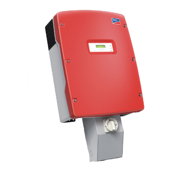
- Page 1 Solar Inverter SUNNY BOY 5000US / 6000US / 7000US / 8000US Installation Guide SB50US-80US-IUS094030 | TBUS-SB50_60_70US | Version 3.0...
- Page 3 (with no limitation) any implied warranties of utility, merchantability, or fitness for any particular purpose. All such warranties are expressly disclaimed. Neither SMA America nor its distributors or dealers shall be liable for any indirect, incidental, or consequential damages under any circumstances.
-
Page 4: Important Safety Instructions
A Warning describes a hazard to equipment or personnel. It calls attention to a procedure or practice, which, if not correctly performed or adhered to, could result in damage to or destruction of part or all of the SMA equipment and/or other equipment connected to the SMA equipment or personal injury. -
Page 5: Other Symbols
SMA Solar Technology AG Other Symbols In addition to the safety and hazard symbols described on the previous pages, the following symbol is also used in this Installation Guide: Information This symbol accompanies notes that call attention to supplementary information that you should know and use to ensure optimal operation of the system. - Page 6 For all repair and maintenance always return the unit to an authorized SMA Service Center. Before installing or using the Sunny Boy, read all of the instructions, cautions, and warnings on the Sunny Boy, the PV array, in this Installation Guide.
-
Page 7: Table Of Contents
5.1.2 Wiring with SMA DC-Disconnect ....... . . 39 Bottom View and Dimensions ......40... - Page 8 5.5.3 AC Wiring With SMA DC-Disconnect......50 Wiring the DC Input ....... . . 54 5.6.1...
- Page 9 Without SMA DC-Disconnect ........97...
- Page 10 SMA Solar Technology AG SB50US-80US-IUS094030 Installation Guide...
-
Page 11: Introduction
SMA Solar Technology AG 1 Introduction This installation guide provides all the information needed to install, commission and operate a Sunny Boy (SB 5000US, SB 6000US, SB 7000US, SB 8000US) grid-tied photovoltaic (PV) inverter. To help avoid problems during the installation, familiarize yourself with the installation process by reading the entire Installation Guide before starting the installation. -
Page 12: Product Overview
Figure below. Sunny Boy Installed in a Utility Interactive PV System Position Description PV array Sunny Boy with SMA DC-Disconnect Local loads Meter Utility Grid Policies vary from one utility company to another. Consult with a representative of the local utility company before designing and installing a PV system. -
Page 13: Safety
SMA Solar Technology AG 1.3 Safety Anti-Islanding Protection Islanding is a condition that can occur if the utility grid is disconnected while the Sunny Boy is operating and the remaining load is resonant at 60 Hz and matches the output of the Sunny Boy perfectly. -
Page 14: Feature Overview
SMA Solar Technology AG Feature Overview Over twenty years of inverter manufacturing experience has gone into the design of the Sunny Boy. As a result, the Sunny Boy represents state-of-the-art technology, high reliability and over all ease of use - all the qualities you’ve come to expect from the industry leader in inverter manufacturing. Some of the features included are: •... -
Page 15: Installation Overview
SMA Solar Technology AG 1.4 Installation Overview This section provides a high-level overview of the installation process so you have an idea what to expect as you proceed through the rest of the Installation Guide. The installation process is broken down into the following tasks:... -
Page 16: Unpacking And Inspection
SMA dealer and to the shipping company that delivered the Sunny Boy. If it becomes necessary to return the Sunny Boy, use the original packaging in which it was delivered. -
Page 17: Scope Of Delivery
(left and right) SMA DC-Disconnect (if applicable): one SMA DC-Disconnect one screw and one washer for closing the SMA DC-Disconnect cover two M6 x 10 screws and two washers for fastening the SMA DC-Disconnect to the wall-mounting bracket Installation Guide... -
Page 18: Ac Voltage Configuration
SMA Solar Technology AG 3 AC Voltage Configuration 3.1 Opening the Sunny Boy 1. Remove the six screws and lock washers from the housing cover and pull the cover forward smoothly. 2. Place the cover, screws, and lock washers aside where they will be out of your way while you are connecting wires and cables to the Sunny Boy. -
Page 19: Locating Internal Components
SMA Solar Technology AG 3.2 Locating Internal Components The figure below illustrates the locations of the major internal components of the Sunny Boy. Refer to this illustration as needed to locate particular components. Position Description Sockets for optional communication Piggy-Back (RS485 or wireless) - Page 20 SMA Solar Technology AG Position Description Ground Terminal (PE) Output AC Line Terminals (N, L1 and L2) PV Grounding + DC Grounding electrode conductor Output AC Line Terminals (L1, L2, N and PE) PV GROUNDED Terminal (input from PV array)
-
Page 21: Configuring The Ac Voltage
SMA Solar Technology AG 3.3 Configuring the AC Voltage The Sunny Boy 8000US may not be connected to a 208 V grid. The Sunny Boy may be easily configured for the different grid types commonly found in the U.S. The Sunny Boy is compatible with: •... -
Page 22: Automatic Grid Voltage Detection
If the utility system has a neutral, the local Authority Having Jurisdiction (AHJ) may require that the neutral be connected to the inverter. Follow the procedure in 3.4 "Utility Configuration Jumpers" (page 24) to set the configuration jumpers and chapter 5.5.2 "AC Wiring Without SMA DC- Disconnect" (page 47) to connect a neutral conductor to the Sunny Boy. - Page 23 SMA Solar Technology AG Common Utility Voltage Configurations The figure below illustrates commonly used transformer types. Remember, when connecting the Sunny Boy to the utility, the phase relationship is not important, but the voltage must be compatible. *The Sunny Boy 8000US may not be connected to a 208 V grid.
-
Page 24: Utility Configuration Jumpers
SMA Solar Technology AG When using 240 V Delta corner grounded, or 208 V Delta corner grounded grids connect the L2 terminal to the grounded corner. 3.4 Utility Configuration Jumpers The utility configuration jumpers allow the Sunny Boy to be connected to transformers where the neutral is not present, such as the 208 V and 240 V Delta, shown in Figure "Common Utility Voltage... - Page 25 SMA Solar Technology AG The figures below illustrate the proper jumper settings when connecting to a 240 Delta: 120V Stinger type transformer, or 240 Delta Corner grounded transformer, respectively. Note the order in which inverters are connected to the phases.
-
Page 26: Mounting
SMA Solar Technology AG 4 Mounting This section provides guidelines to help you select the best mounting location, suggestions to insure optimum performance, cautions and warnings that you should follow to avoid injury and/or equipment damage, and step-by-step instructions for mounting a Sunny Boy inverter. -
Page 27: Ambient Conditions
SMA Solar Technology AG • The Sunny Boy emits a slight vibrating noise when operating. This vibration is normal and has no effect on performance, but it can be objectionable if the inverter is mounted on a wall in a living area, on the outside of a wall that is near a living area, or on certain types of materials, such as thin wood panelling or sheet metal. -
Page 28: Dimensions And Required Clearances
SMA Solar Technology AG 4.2 Dimensions and Required Clearances CAUTION! If you are installing the Sunny Boy in a cabinet, closet, or other relatively small enclosed area, you must provide sufficient air circulation to dissipate the heat generated by the inverter. - Page 29 SMA Solar Technology AG Dimensions of the Wall Mounting Bracket Installation Guide SB50US-80US-IUS094030...
- Page 30 SMA Solar Technology AG Dimensions for the installation of the conduits SB50US-80US-IUS094030 Installation Guide...
-
Page 31: Mounting Procedure
SMA Solar Technology AG 4.3 Mounting Procedure 4.3.1 Mounting the Wall-Mounting Bracket The Sunny Boy is shipped with a T-shaped wall-mounting bracket that is suitable for use with most walls (see Figures below). The horizontal part of the bracket has 12 holes. Use the 4 outermost holes of the wall-mounting bracket for mounting on wooden stud walls. - Page 32 SMA Solar Technology AG Mounting Bracket - Wood Wall Mounting with 2 Studs Use the following procedure to mount the wall-mounting bracket: WARNING! To prevent electrical shock or other injury, check for existing electrical or plumbing installations in the walls before drilling mounting holes for the Sunny Boy.
-
Page 33: Mounting The Sma Dc-Disconnect (If Applicable)
Tighten the screws until the bracket is held firmly against the wall. Do not overtighten the screws. 4.3.2 Mounting the SMA DC-Disconnect (if applicable) Attach the SMA DC-Disconnect to the two lower holes of the wall-mounting bracket, using two M6 x 10 screws and washers provided. The teeth of the washers should face towards the wall in order to ensure proper grounding. -
Page 34: Mounting The Sunny Boy
4. Close the fan outputs with the handle covers (see # 3 in Figure above) provided in the accessories kit. They are required to adequately prevent insects entering the unit. Should the handle covers break, new handle covers can be ordered from SMA America. 5. Carefully verify that the Sunny Boy is firmly mounted in place. - Page 35 SMA Solar Technology AG 6. When the Sunny Boy has been mounted correctly it should look like one of the examples in Figure below. Installation Guide SB50US-80US-IUS094030...
-
Page 36: Wiring The Sunny Boy
SMA Solar Technology AG 5 Wiring the Sunny Boy This section provides step-by-step procedures and other information required for wiring the Sunny Boy to the PV array and the utility grid. To complete the installation in a safe and efficient manner, complete the steps in the order that they appear. - Page 37 SMA Solar Technology AG DC Grounding Electrode Conductor A DC grounding electrode conductor may be required by the Authority Having Jurisdiction (AHJ) Use the PV Grounding and DC Grounding Electrode Conductor (see 3.2 "Locating Internal Components" (page 19)). Installation Guide SB50US-80US-IUS094030...
-
Page 38: Sequence Of Connecting
SMA Solar Technology AG 5.1 Sequence of Connecting 5.1.1 Wiring without SMA DC-Disconnect WARNING! Always connect the wires to the Sunny Boy in the following sequence: 1. De-energize all energy sources by opening all AC and DC disconnects and/or breakers. 2. Wiring from AC breaker to the AC disconnect switch. -
Page 39: Wiring With Sma Dc-Disconnect
2. Wiring from the AC breaker to the SMA DC-Disconnect, follow the procedure on page 50 et seq.. 3. AC wiring from the SMA DC-Disconnect to the Sunny Boy, follow the procedure on page 50 et seq.. 4. Wiring from the PV array to the SMA DC-Disconnect, follow the procedure on page 60 et seq.. -
Page 40: Bottom View And Dimensions
Information The AC and DC knockouts are sized for 3/4 inch rigid conduit (EMT). DO NOT enlarge any of these holes, as this is a violation of UL requirements and will void the SMA warranty. 5.3 Opening the Sunny Boy 1. Remove the six screws from the housing cover and pull the cover forward smoothly. -
Page 41: Opening The Sma Dc-Disconnect (If Applicable)
1. Turn the SMA DC-Disconnect off by turning the switch to "0". 2. Loosen screw in the right area of the SMA DC-Disconnect with a small phillips screwdriver (used screw: UNC no 5 x 3/4“, cross recess Phillips pan head machine screw). Do not remove the screw. -
Page 42: Wiring The Ac Output
SMA Solar Technology AG 5.5 Wiring the AC Output This subsection provides complete, step-by-step procedures for wiring the AC output from the Sunny Boy to the utility grid. 5.5.1 AC Connection Requirements WARNING! All electrical installations must be done in accordance with all local electrical codes and with the National Electrical Code (NEC), ANSI/NFPA 70. - Page 43 SMA Solar Technology AG Sunny Boy 5000US Energy Losses in Various Wire Sizes and Wire Lengths Percent voltage drop for 208 V AC and 240 V AC service Percent voltage drop for 277 V AC service Installation Guide SB50US-80US-IUS094030...
- Page 44 SMA Solar Technology AG Sunny Boy 6000US Energy Losses in Various Wire Sizes and Wire Lengths Percent voltage drop for 208 V AC and 240 V AC service Percent voltage drop for 277 V AC service SB50US-80US-IUS094030 Installation Guide...
- Page 45 SMA Solar Technology AG Sunny Boy 7000US Energy Losses in Various Wire Sizes and Wire Lengths Percent voltage drop for 208 V AC and 240 V AC service Percent voltage drop for 277 V AC service Installation Guide SB50US-80US-IUS094030...
- Page 46 SMA Solar Technology AG Sunny Boy 8000US Energy Losses in Various Wire Sizes and Wire Lengths Percent voltage drop for 240 V AC service Percent voltage drop for 277 V AC service SB50US-80US-IUS094030 Installation Guide...
-
Page 47: Ac Wiring Without Sma Dc-Disconnect
SMA Solar Technology AG 5.5.2 AC Wiring Without SMA DC-Disconnect Use the following procedure to connect the AC wires to the Sunny Boy without the SMA DC- Disconnect: WARNING! You must connect the wires that carry the AC voltage from the Sunny Boy to the utility grid in the order described in this procedure. - Page 48 SMA Solar Technology AG The terminal must be opened completely before you insert the cable. 11. Connect the wires to the terminal blocks in the Sunny Boy and tighten them. Torques for AC connection terminal blocks: Grey Terminal Blocks (Weidmüller)
- Page 49 SMA Solar Technology AG AC Connection Terminals for 277 V Position Description L1 wire connected to L1 terminal N wire connected to N terminal Equipment ground wire connected to PE terminal Installation Guide SB50US-80US-IUS094030...
-
Page 50: Ac Wiring With Sma Dc-Disconnect
4. Install a 3/4-inch conduit fitting in the SMA DC-Disconnect AC wiring knockout (the knockout on the right side of the SMA DC-Disconnect). Fasten the conduit fitting on the inside of the SMA DC-Disconnect with the appropriate locknut. - Page 51 N in the SMA DC-Disconnect. Note: For 277 V the L2 terminal is not used. 10. Connect the wires to the terminal blocks in the SMA DC-Disconnect and tighten to a torque of 15 in-lb (1.7 Nm). 11. Use a screwdriver in order to poke a hole in the groove of the grommet inside the inverter.
- Page 52 15. Connect the green/yellow cable of the Sunny Boy to the terminal labeled: 16. Connect the white wire of the SMA DC-Disconnect to the terminal labeled N and the black wire to the terminal labeled L1 of the Sunny Boy.
- Page 53 SMA Solar Technology AG For 277 V connect the red wire to the terminal labeled in the Sunny Boy (not used). 18. Connect the wires to the terminal blocks in the Sunny Boy and tighten them. Torques for AC connection terminal blocks: Grey Terminal Blocks (Weidmüller)
-
Page 54: Wiring The Dc Input
SMA Solar Technology AG 5.6 Wiring the DC Input This subsection provides procedures for wiring the DC input from the PV array to the Sunny Boy. The figure below shows a simplified wiring diagram of a PV system. Simplified Electrical Wiring Diagram of a PV System... -
Page 55: Dc Connection Requirements
The SMA DC disconnect is shipped with four 15 A, 600 V DC fuses (one for each string). The maximum fuse rating for the four SMA DC disconnect fuses is 20 A, 600 V DC (one for each string). For fuse sizing please refer to NEC 690.9. -
Page 56: Dc Input Grounding
SMA Solar Technology AG 5.7 DC Input Grounding The Sunny Boy comes from the factory configured for negative ground systems. Certain types of PV modules may require that the positive terminal be grounded instead of the negative terminal. To configure the Sunny Boy for positive ground, move the fuse (1) and change the jumper position (2) as shown in the following illustrations. -
Page 57: Connecting The Dc Wires
DC-input-voltage range will cause irreversible damage to the Sunny Boy and void the warranty! Always configure the DC-input-voltage range correctly before connecting the DC-input wires from the PV array to the Sunny Boy. Use the online SMA string size calculator at www.sma-america.com to determine the correct string configuration. -
Page 58: Dc Wiring Without Sma Dc-Disconnect
SMA Solar Technology AG 5.8.1 DC Wiring Without SMA DC-Disconnect Use the following procedure to connect the DC wires to the Sunny Boy without SMA DC-Disconnect: 1. Verify that the AC breaker is OFF. 2. Verify that the DC disconnect is open in the external DC disconnect enclosure. - Page 59 SMA Solar Technology AG CAUTION! Avoid using wire nuts to join any wires together or to make any connections anywhere in the PV system. Wire nuts are a frequent cause of unreliable, resistive connections, and ground faults. The terminal must be opened completely before you insert the cable.
-
Page 60: Dc Wiring With Sma Dc-Disconnect
1. Verify that the AC breaker is OFF. 2. Install a 3/4-inch conduit fitting in the SMA DC-Disconnect’s DC wiring knockout (the knockout on the left side of the SMA DC-Disconnect). Fasten the conduit fitting on the inside of the SMA DC-Disconnect with the appropriate locknut. - Page 61 8. Connect the negative DC wires (A) to the terminal labeled PV GROUNDED in the SMA DC-Disconnect. 9. Torque all wires in the terminal blocks inside the SMA DC-Disconnect to 15 in-lb (1.7 Nm). 10. Use a screwdriver in order to poke a hole in the groove of the grommet.
- Page 62 SMA Solar Technology AG 12. Pull the DC wires from the DC disconnect through the conduit into the interior of the Sunny Boy. 13. Pull the wires slightly back in order to seal the grommet. 14. Connect the black wire (PV UNGROUNDED) to the terminal labeled DC+ in the Sunny Boy.
- Page 63 2. Connect the positive DC wires (A) to the terminal labeled PV GROUNDED in the SMA DC-Disconnect. 3. Torque all wires in the terminal blocks inside the SMA DC-Disconnect to 15 in-lb (1.7 Nm). 4. Use a screwdriver in order to poke a hole in the groove of the grommet.
- Page 64 SMA Solar Technology AG 6. Pull the DC wires from the DC disconnect through the conduit into the interior of the Sunny Boy. 7. Pull the wires slightly back in order to seal the grommet. 8. Connect the white wire (PV GROUNDED) to the terminal labeled DC+ in the Sunny Boy.
-
Page 65: Dc Connection With Additional Dc Distribution
COMBINED in the SMA DC-Disconnect. 2. Connect the negative DC wire (A) to the terminal labeled PV GROUNDED in the SMA DC-Disconnect. 3. Torque all wires in the terminal blocks inside the SMA DC-Disconnect to 15 in-lb (1.7 Nm). Installation Guide SB50US-80US-IUS094030... -
Page 66: Communication
2. Connect the positive DC wire (A) to the terminal labeled PV GROUNDED in the SMA DC-Disconnect. 3. Torque all wires in the terminal blocks inside the SMA DC-Disconnect to 15 in-lb (1.7 Nm). 5.9 Communication The Sunny Boy can be retrofitted with a communication interface (socket see section 3.2 "Locating Internal Components"... - Page 67 SMA Solar Technology AG CAUTION! Be careful not to misplace the screws or the lock washers that attach the cover to the case, as all six screws and lock washers are required to ensure that the cover is grounded properly and is fully sealed to the case. Handle the cover carefully, as even minor damage to the cover could result in an inadequate seal between the cover and the case, thus allowing moisture to enter the case and damage the sensitive electronic components.
-
Page 68: Closing The Sma Dc-Disconnect (If Applicable)
4. Install the screw and washer on the bottom side of the SMA DC-Disconnect, to fasten the cover. The teeth of the washer must face toward the cover in order to ensure proper grounding. Tighten the screw to a torque of 44 in-lb (5 Nm). -
Page 69: Commissioning
2. Connect the grid voltage to the Sunny Boy by switching on the main AC circuit breaker in the main utility panel. 3. Switch the external DC disconnect to the „on“ position or switch the SMA DC-Disconnect to the “1“ position. If there is sufficient sunlight available, the Sunny Boy will enter the “Wait” mode at this time and the green LED will begin to blink. - Page 70 SMA Solar Technology AG If the Sunny Boy is not operating as expected after the commissioning procedure has been completed, refer to Section 7 "Displays and Messages" (page 71) and to Section 8 "Troubleshooting" (page 86). If there is adequate solar irradiation and the resulting PV input voltage is greater than 300 V DC (365 V DC for Sunny Boy 8000US), the Sunny Boy will automatically begin feeding power to the utility grid.
-
Page 71: Displays And Messages
SMA Solar Technology AG 7 Displays and Messages The Sunny Boy LED Status Indicator Each Sunny Boy inverter comes equipped with three LED status indicators. (Shown in the figure above) This allows the user to determine the operating mode of the inverter at a glance. -
Page 72: Led Operation Indicators
SMA Solar Technology AG The red and yellow LEDs combined indicate that the inverter has detected a ground fault. The ground fault must be located and cleared and the inverter reset manually. The inverter will not restart automatically after detecting a ground fault. -
Page 73: Normal Operation
SMA Solar Technology AG Starting The inverter has sufficient PV power to calibrate its internal systems, but not enough to begin normal operation. Typically, the calibration lasts less than 10 seconds and then the inverter resumes normal operation. PV voltage must remain > PV Start Voltage setting for the period of the P-Start parameter setting. -
Page 74: Led Fault Indicators
SMA Solar Technology AG Derating The Sunny Boy is designed to operate at full rated power up to 45°C ambient. The inverter will continue to operate beyond 45°C and will derate as required to maintain a safe internal component temperature. Unnecessary derating can be caused by blocked fan intakes. For this reason the fan intakes should be inspected often and cleaned when needed. -
Page 75: Grid Failure
The Sunny Boy has detected a fault within the internal monitoring systems. When the inverter detects a fault of this kind it will no longer connect to the utility grid. To correct this, the inverter must be serviced by a qualified service technician. Contact SMA America for assistance. Grid Failure The yellow LED is on for 5 seconds, out for 3 seconds and then blinks twice. - Page 76 SMA Solar Technology AG WARNING! If opening the Sunny Boy is required, do so only after disconnecting all sources of power and waiting at least 5 minutes. High DC Input Voltage The yellow LED is on for 5 seconds, remains off for 3 seconds and then blinks 4 times. The code is repeated 3 times.
-
Page 77: Status Messages On The Lcd Display
The inverter has encountered an internal fault that prohibits normal operation and will most likely require servicing. Contact SMA America for assistance. 7.3 Status Messages on the LCD Display The Sunny Boy comes standard with the “Sunny Display“ LCD in the lid. -
Page 78: Fault Messages
SMA Solar Technology AG The installed firmware versions of the control system processor (BFR) and the current regulator processor (SRR) are displayed after 6 seconds. Operation Messages The LCD continuously scrolls through all relevant operating data. Each message (MSG) is displayed for 5 seconds, after all messages have been displayed the LCD repeats from the beginning. - Page 79 SMA Solar Technology AG • Warning For example, this Warning message would be displayed if the GFDI fuse was open or cleared. Typically, Warning messages indicate a system condition that should be investigated. Warning conditions will not preclude inverter operation.
-
Page 80: Lcd Display Language Selection
SMA Solar Technology AG 7.3.1 LCD Display Language Selection The LCD Display has the ability to display information in one of four different languages. Setting the language is performed by using a pair of slide switches located along the bottom edge of the display PC board. -
Page 81: Measuring Channels And Parameters
SMA Solar Technology AG 7.4 Measuring Channels and Parameters The communication options support a number of measuring channels and messages from the Sunny Boy inverters. The following abbreviations are used: Betriebsführungsrechner (Sequential Control System) Stromregelungsrechner (Current Control System) The BFR and SRR are redundant processor control systems for the utility protection functions. -
Page 82: Operating Mode
SMA Solar Technology AG 7.4.2 Operating Mode Stop: Manual system stop Offset: Offset calibration of the electronics (at start-up) Waiting: PV voltage is not high enough to start Grid monitoring: Synchronizing to grid (at start-up) MPP-Search: MPPT range test (at start-up) - Page 83 SMA Solar Technology AG Name Unit Range Default Password Description Level dFac-MAX* Hz/s 0.005 ... 4 0.5 (for Installer Maximum “rate of frequency country setting change” before anti-islanding USA/ protection engages UL1741/ 2005) E_Total 0 ... 200000 Installer Total energy yield of the inverter.
- Page 84 SMA Solar Technology AG Name Unit Range Default Password Description Level T-Start 5 ... 1600 Installer The time the inverter waits to connect to the grid after Vpv-Start is exceeded. This value defaults to 5 minutes after a utility fault.
- Page 85 SMA Solar Technology AG Table 7-2: Operating Parameters of the Sunny Boy (Fixed) Name Unit Range Default Description Plimit fixed SB5000US: 5100 Upper limit of AC output power SB6000US: 6100 SB7000US: 7100 SB8000US: 8100 SMA-SN Serial Number of the Sunny Boy...
-
Page 86: Troubleshooting
• If the system problem persists, contact SMA America technical support at: (916)625-0870. In order to better assist you when contacting SMA America, please provide the following information. This information is required for service assistance. Information Regarding the Sunny Boy: •... -
Page 87: Error Messages
If the grid frequency is within the tolerable range and you still observe the failure message “Fac- Bfr“ or “Fac-Srr“ contact SMA. Warning GFDI Fuse Open The GFDI-Fuse is open or cleared. Check PV array for ground faults before replacing the fuse. - Page 88 This may happen in case of harmfull interference on the grid. If you observe “Imax“ often, check your grid. For assistance contact SMA. Disturbance K1-Close Relay test failed. Contact SMA for assistance. Error K1-Open, K2-Open Disturbance MSD-FAC, MSD-Idif Internal measurement comparison error: The...
- Page 89 SMA Solar Technology AG Error Type Error Code Description Disturbance XFMR Transformer is connected to the wrong grid. Check the connection of the transformer. In Delta corner grounded grids make sure that the Ground of the grid is connected to the terminal L2 In unbalanced 208 V and 240 V grids interchanging L1 and L2 may clear this error.
-
Page 90: Maintenance
SMA Solar Technology AG 9 Maintenance The Sunny Boy is designed to provide many years of trouble-free service. Performing regular maintenance will help ensure the long life and high efficiency of your system. 9.1 Cleaning the Fans The fan intakes and handle covers should be cleaned periodically with a vacuum cleaner. (Do not blow air into the fan areas) For deeper cleanings, the fans can be removed completely. -
Page 91: Cleaning The Handle Covers
The handle covers must not be removed permanently, because otherwise the device is not protected against the entrance of insects! Should the handle covers break, new handle covers can be ordered from SMA America. Installation Guide SB50US-80US-IUS094030... -
Page 92: Testing The Fans
• Once the LED’s are off, remove the cover and set the jumpers as shown in the figure below. • Turn on the inverter by turning on the AC disconnect and then the DC disconnect or switch the SMA DC-Disconnect to the "1" position. Jumper Position for Fan Test... -
Page 93: Exchanging The Fuses
SMA Solar Technology AG 9.4 Exchanging the Fuses 9.4.1 Exchanging the GFDI Fuse within the Sunny Boy 1. Turn OFF all AC and DC switches and/or breakers. 2. Wait for at least 5 minutes. 3. Open the Sunny Boy as described in section 3.1 "Opening the Sunny Boy" (page 18). -
Page 94: Exchanging The Pv String Fuses Within The Sma Dc-Disconnect
1. Turn OFF all AC and DC switches and/or breakers. 2. Wait for at least 5 minutes. 3. Open the SMA DC-Disconnect as described in section 5.4 "Opening the SMA DC-Disconnect (if applicable)" (page 41). 4. Exchange the fuses having regard to the information on the next page. - Page 95 PV String Fuses The SMA DC-Disconnect is shipped with 15 A, 600 V DC fuses in the fuse holders. The maximum string fuse rating for the SMA DC-Disconnect is 20 A. The figure in chapter 9.4.2 "Exchanging the PV String Fuses within the SMA DC-Disconnect"...
-
Page 96: Technical Specifications
• Consult the dealer or an experienced radio/TV technician for help. • The user is cautioned that changes or modifications not expressly approved by SMA America, Inc. could void the user’s authority to operate this equipment. Contact SMA America for more information. -
Page 97: Sunny Boy Wiring Diagrams
SMA Solar Technology AG 10.2 Sunny Boy Wiring Diagrams 10.2.1 Without SMA DC-Disconnect Sunny Boy Connections for 208 and 240 V AC grids Sunny Boy Connections for 277 V AC grids Installation Guide SB50US-80US-IUS094030... -
Page 98: With Sma Dc-Disconnect
SMA Solar Technology AG 10.2.2 With SMA DC-Disconnect Sunny Boy Connections for 208 and 240 V AC grids Sunny Boy Connections for 277 V AC grids SB50US-80US-IUS094030 Installation Guide... -
Page 99: Specifications
SMA Solar Technology AG 10.3 Specifications 10.3.1 Sunny Boy 5000US and Sunny Boy 6000US SB 5000US SB 6000US Inverter Technology True sine wave, low frequency tranformer AC Operating Voltage 183 - 229 (208 V nominal) Range 211 - 264 (240 V nominal) -
Page 100: Sunny Boy 7000Us And Sunny Boy 8000Us
SMA Solar Technology AG SB 5000US SB 6000US Maximum Output Fault 57.6 A Current Maximum Output 50 A Overcurrent Protection Synchronization In-Rush 9.23 A Current Trip Limit Accuracy ± 2 % Trip Time Accuracy ± 0.1 % DC Voltage Ripple... - Page 101 SMA Solar Technology AG SB 7000US SB 8000US Maximum AC 7000 W 8000 W Continuous Output Power Current THD Less than 4 % Output Power Factor 0.95 - 1.0 (0.99 @ nominal conditions) Peak Inverter Efficiency 97.1 % 96.5 % CEC weighted 95.5 % at 208 V AC...
-
Page 102: Sma Dc-Disconnect
SMA Solar Technology AG SB 7000US SB 8000US Compliance UL1741, UL 1998, IEEE 1547, IEEE 929, IEEE C37.90.1, IEEE C62.41.2 (test conditions 2 kV / 1 kA), FCC Part 15 A & B Specifications subject to change without notice. Values at nominal conditions. -
Page 103: Trip Limits / Trip Times
SMA Solar Technology AG 10.4 Trip Limits / Trip Times Nominal Trip Limit (Hz) Trip Frequencies (Hz) Trip Times (s) Freq. (Hz) > 60.5 60.45 - 60.55 max. 0.1602 < 57.0 - 59.8 56.95 - 59.85 adjustable 0.16 - 300 (default 59.3) (default 59.25 - 59.35) -
Page 104: Torque Values And Wire Sizes
10 AWG Grey AC Configuration Terminal Blocks for Unused Wires (Weidmüller) Green AC Configuration Terminal Blocks for Unused Wires (Phoenix) AC & DC Terminal Blocks SMA 10 - 6 AWG DC-Disconnect Combined Terminal Block SMA Spring Spring 10 - 6 AWG... - Page 105 SMA Solar Technology AG Installation Guide SB50US-80US-IUS094030...
- Page 106 SMA Solar Technology AG SB50US-80US-IUS094030 Installation Guide...
Need help?
Do you have a question about the Sunny Boy 6000US and is the answer not in the manual?
Questions and answers