Sign In
Upload
Manuals
Brands
Vertiv Manuals
Power distribution unit
NetSure 8100DB
Vertiv NetSure 8100DB Manuals
Manuals and User Guides for Vertiv NetSure 8100DB. We have
2
Vertiv NetSure 8100DB manuals available for free PDF download: Installation And User Manual, System Application Manual
Vertiv NetSure 8100DB Installation And User Manual (98 pages)
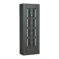
48 VDC Power Distribution System
Brand:
Vertiv
| Category:
Power distribution unit
| Size: 8 MB
Table of Contents
Table of Contents
3
Admonishments Used in this Document
5
Important Safety Instructions
6
General Safety
6
DC Voltages
6
Personal Protective Equipment (PPE)
7
Handling Equipment Containing Static Sensitive Components
7
Maintenance and Replacement Procedures
7
Static Warning
8
Customer Documentation Package
9
System Description
9
Installation Acceptance Checklist
10
Physically Installing the System
11
General Requirements
11
Installing the Bays
11
Installing Distribution Panel Paralleling Bars (if Furnished)
13
Installing the Internal Ground/Return Busbar Paralleling Bars List
14
(8-Panel Bay Only) (if Furnished)
14
Field Installing Bay Input Feed and Shunt Assembly List 43
15
Making Switch and Jumper Settings
21
Circuit Cards with Jumpers And/Or Switches Locations
21
Switch Settings on IB2 Interface Board
22
Switch Settings on SM-DUE
23
Jumper Settings on SM-DUE
25
Analog Inputs AI1 to AI10
25
Switch Settings on SM-DUH2
27
Making Electrical Connections
29
Important Safety Instructions
29
Wiring Considerations
29
Bay Overall Connections Diagram
30
Bay Frame Grounding Connection
31
External Alarm, Reference, Monitoring, and Control Connections
32
Circuit Card Locations
32
IB2 (Interface Board) Connections
32
Auxiliary Fuse Board Connections
35
Ground/Return Input Connections for Auxiliary Fuse Card
37
System Ethernet Port Connections
38
Monitor Unit Top Panel Ethernet Port
38
IB4 Board Ethernet Port
38
Installing and Wiring to an Optional Transient Voltage Surge
39
Suppressor (TVSS) Device
39
Input/Output Cable Routing and Cable Management
41
Load Distribution Connections
45
DC Input Connections
53
Installing Circuit Breakers and Fuses
58
Initially Starting, Configuring, and Checking System Operation
62
Important Safety Instructions
62
Initial Startup Preparation
62
Initially Starting the System
62
Monitor Unit Initialization
62
Application
64
Checking System Status
66
Final Steps
67
Operating the System
68
Monitor Unit
68
Local Controls and Indicators
68
Maintenance
72
Important Safety Instructions
72
Routine Maintenance
72
System Expansion
72
Troubleshooting and Repair
77
Important Safety Instructions
77
Contact Information
77
Monitor Unit
77
System Troubleshooting Information
77
Replacement Information
77
Replacement Procedures
77
Replacing the Monitor Unit
77
Replacing a Distribution Device
78
Circuit Card Replacement Procedures
82
Replacing a Distribution Panel
94
Replacing an Output Bar with Sensor in a List 15A or List 25A Distribution Panel
96
Advertisement
Vertiv NetSure 8100DB System Application Manual (67 pages)
Brand:
Vertiv
| Category:
Industrial Electrical
| Size: 5 MB
Table of Contents
System Overview
1
Spec. No. 582140600 (Model
3
Table of Contents
4
Eight Panel Bay
6
Main Components Illustrations
6
List
7
Six Panel Bay
8
List
9
List Descriptions (582140600)
10
List Numbers
10
582140600 List 01: Common Equipment, 6-Panel Bay, 30" W X 16" D X 84" H
10
582140600 List 03: Common Equipment, 6-Panel Bay, 30" W X 24" D X 84" H
11
582140600 List 07: Common Equipment, 8-Panel Bay, 30" W X 16" D X 84" H
12
582140600 List 09: Common Equipment, 8-Panel Bay, 30" W X 24" D X 84" H
13
582140600 List 10: TLS/TPS Fuse And/Or TPL-B Fuse Distribution Panel, 8-Panel Bay
14
582140600 List 15: Bullet Breaker And/Or TLS/TPS Fuse Distribution Panel, 8-Panel Bay
14
Monitoring, 8-Panel Bay
15
582140600 List 16: Optional Internal Ground/Return Bar, 8-Panel Bay (Full Bay Length)
15
Revision E, November
15
582140600 List 17: Optional Internal Ground/Return Bar, 8-Panel Bay (Panel Length)
16
582140600 List 18: Blank Distribution Panel Cover, 8-Panel Bay
16
Revision E, November
16
582140600 List 20: TLS/TPS Fuse And/Or TPL-B Fuse Distribution Panel, 6-Panel Bay
17
582140600 List 25: Bullet Breaker And/Or TLS/TPS Fuse Distribution Panel, 6-Panel Bay
17
582140600 List 26: Optional Internal Ground/Return Bar, 6-Panel Bay (Full Bay Length)
18
Monitoring, 6-Panel Bay
18
582140600 List 27: Optional Internal Ground/Return Bar, 6-Panel Bay (Panel Length)
19
582140600 List 28: Blank Distributional Panel Cover, 6-Panel Bay
19
582140600 List 30: Distribution Panel Paralleling Bar, 6-Panel Bay
20
582140600 List 31: Distribution Panel Paralleling Bar, 8-Panel Bay
20
582140600 List 39: Optional Internal Ground/Return Bar Paralleling Kit, 8-Panel Bay (Panel Length)
20
582140600 List 43: Bay Input Feed and Shunt Assembly (4 Cables, 25 MV Shunts)
20
582140600 List 48: 2400 a Ground/Return Input Assembly, with Optional Bonding Strap
21
582140600 List 51: Dressing Bar, 16" Deep Bays
21
582140600 List 52: Dressing Bar, 24" Deep Bays
21
582140600 List 53: Load Distribution Cable Management Kit
22
582140600 List 54: Top Cover, 16" Deep
22
582140600 List 55: Top Cover, 24" Deep
22
582140600 List 67: Pre-Installed Load Lug-Mounting Hardware
22
Accessory Descriptions
23
Load Lug Hardware Kits, P/N 547682 and 547683
23
Side by Side Distribution Panel Paralleling Bar, P/N 563497
23
Distribution Device Numbering Scheme Reversing Kit, P/N 565436 and 565437
24
Lug Adaptor Kits
25
P/Ns 556377 and 556378
25
P/Ns 564906 and 564907
26
Special Lugs and Adapters
27
External Return/Ground Bar Assemblies
28
Standard Crimp Lug Tables
29
Seismic Anchor Kit, P/N 545387
30
Transient Voltage Surge Suppressor (TVSS) Device
30
Distribution Devices and Lug Selection
31
List 10 and List 20 Fuse Panels
31
List 15, List 15A, List 25, and List 25A Fuse/Circuit Breaker Panels
35
User Replaceable Alarm, Reference, and Control Fuses
39
Fuses Located on Auxiliary Fuse Card at Top of Bay
39
User Replaceable Components
39
Recommended Wire Sizes, Branch Circuit Protection, Crimp Lugs, and Wiring Illustrations
40
Overall Installer's Connections Illustration
40
Bay Frame Grounding Requirements
41
General
41
Bay Frame Grounding Connection
41
Auxiliary Fuse Circuit Card
42
Monitor Unit Ethernet Connection (if Required)
43
To Monitor Unit
43
To IB4 Board
43
Load Distribution Connections
44
General
44
Load Distribution Connections Illustrations
48
DC Input Connections
54
General
54
DC Input Connections
55
Specifications
58
System
58
1.1 DC Operating Voltage
58
1.2 Environmental Ratings
58
1.3 Compliance Information
58
1.4 Output Ratings
58
1.5 Standard Features
58
Monitor Unit
59
Mechanical Specifications
60
List 01 and List 07 Floor Hole Drilling Pattern Dimensions
60
List 03 and List 09 Floor Hole Drilling Pattern Dimensions
60
Overall Dimensions, List 01
61
Overall Dimensions, List 03
62
Overall Dimensions, List 07
63
Overall Dimensions, List 09
64
Weights
65
Related Documentation
66
Revision Record
67
Advertisement
Related Products
Vertiv NetSure 8100 Series
Vertiv Netsure RDB Series
Vertiv NetSure 563171
Vertiv NetSure 562579
Vertiv NetSure 8200 Series
Vertiv NetSure 8200NLDB
Vertiv NetSure 8200NLEB
Vertiv NetSure 801NLDB
Vertiv NetSure 801NLEB
Vertiv NetSure 802
Vertiv Categories
UPS
Power Supply
Switch
Power distribution unit
Air Conditioner
More Vertiv Manuals
Login
Sign In
OR
Sign in with Facebook
Sign in with Google
Upload manual
Upload from disk
Upload from URL