SMC Networks HRL300-A*-20 Series Operation Manual
Thermo chiller
Hide thumbs
Also See for HRL300-A*-20 Series:
- Operation manual (76 pages) ,
- Operation manual (56 pages)
Table of Contents
Troubleshooting

Related Manuals for SMC Networks HRL300-A*-20 Series


Summary of Contents for SMC Networks HRL300-A*-20 Series
- Page 1 HRX-OM-W060 Operation Manual Installation ・ Operation Original Instructions Thermo Chiller HRL Series HRL100-A HRL200-A HRL300-A Keep this manual available whenever necessary © 2019 SMC CORPORATION All Rights Reserved...
- Page 2 To the users Thank you for purchasing SMC’s Thermo chiller (hereinafter referred to as the “product”). For safety and long life of the product, be sure to read this operation manual (hereinafter referred to as the “manual”) and clearly understand the contents. ●...
-
Page 3: Table Of Contents
HRX-OM-W060 Contents Contents Chapter 1 Safety Instructions ............1-1 Before Using the Product ..................1-1 Reading the Manual ....................1-1 Hazards ........................1-2 1.3.1 Level of hazards ........................1-2 Definition of “Serious injury” and “Minor injury” ..............1-2 1.3.2 Product Label ......................1-3 Safety Measures ...................... - Page 4 HRX-OM-W060 Contents Chapter 4 Starting the Product ............4-1 Before Starting ......................4-1 Preparation for Start ....................4-2 4.2.1 Power supply ........................4-2 4.2.2 Operation screen (home screen) ..................4-3 Preparation of Circulating Fluid Supply to User's Equipment ......4-4 Operation Start and Stop ..................
- Page 5 HRX-OM-W060 Contents ・Setting of the usage time of dustproof filter ..................5-21 5.4.6 Software version screen .....................5-22 5.4.7 CH1 setting screen ......................5-22 ・Temperature rise/drop alarm (AL10/AL11)..................5-23 ・TEMP READY alarm (AL12) of TEMP READY function ..............5-25 ・Offset (TEMP OFFSET) function ....................5-28 ・Pump operation mode ........................5-31 ・Discharge pressure alarm (AL18/AL19/AL20) ................5-32 5.4.8 CH2 setting screen ......................5-34...
- Page 6 HRX-OM-W060 Contents 7.3.1 Discharge of the circulating fluid ..................7-5 Replacement of consumables ................. 7-7 7.4.1 Replacing Particle Filters ..................... 7-7 7.4.2 Replacing the DI filter ......................7-8 7.4.3 Consumables ........................7-10 Chapter 8 Documents ............... 8-1 Specifications ......................8-1 8.1.1 HRL100/200/300-A-20 .......................
-
Page 7: Chapter 1 Safety Instructions
HRX-OM-W060 Chapter 1 Safety Instructions Chapter 1 Safety Instructions Before using the product, be sure to read and understand all the important actions highlighted in this manual. 1.1 Before Using the Product This chapter is intended to specifically describe the safety related issues for handling the product. -
Page 8: Hazards
HRX-OM-W060 Chapter 1 Safety Instructions 1.3 Hazards 1.3.1 Level of hazards The instructions given in this manual aim to assure the safe and correct operation of the product, and to prevent injury of operators or damage to the product. These instructions are grouped into three categories, Danger, Warning and Caution, which indicate the level of hazard, damage and also the degree of emergency. -
Page 9: Product Label
HRX-OM-W060 Chapter 1 Safety Instructions 1.4 Product Label Information about the product, such as Serial No. and Model No. can be found on the product label. This information is needed when contacting an SMC sales distributor. Model number Serial number Kind and amount of refrigerant * (An example of "HRL200-A-20"... -
Page 10: Safety Measures
HRX-OM-W060 Chapter 1 Safety Instructions 1.5 Safety Measures 1.5.1 Safety instructions for use Follow the instructions below when using the product. Failure to follow the instructions may cause an accident and injury. Read and understand this manual carefully before using the product. ... -
Page 11: Emergency Measures
HRX-OM-W060 Chapter 1 Safety Instructions 1.6 Emergency Measures When emergency conditions such as natural disaster, fire, earthquake and injury occur, shut off the breaker of the user’s power supply that supplies power to the product. Even when the power supply swtich is turned off, some of the internal circuits are still energized, unless the user’s power supply is shut off. -
Page 12: Safety Data Sheet(Sds
HRX-OM-W060 Chapter 1 Safety Instructions 1.8 Safety Data Sheet(SDS) If the safety data sheets of chemicals used in this product are needed, contact an SMC's sales distributor. Any chemicals used by the user must be accompanied by an SDS. ( )... -
Page 13: Chapter 2 Name And Function Of Parts
HRX-OM-W060 Chapter 2 Name and Function of Parts Chapter 2 Name and Function of Parts 2.1 Model Number of Product The product can be ordered with the model number configured as shown below. The product needs to be handled in different ways depending on the part number. -
Page 14: Name And Function Of Parts
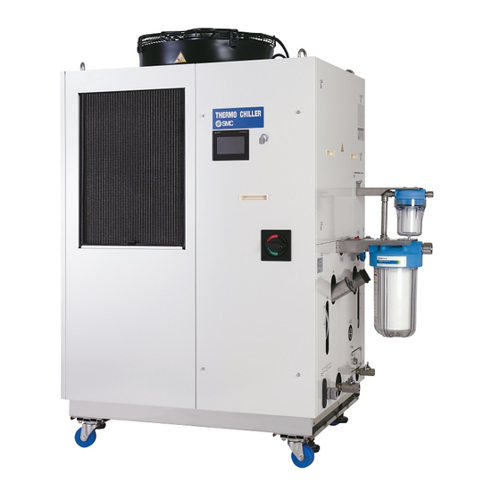
HRX-OM-W060 Chapter 2 Name and Function of Parts 2.2 Name and Function of Parts 2.2.1 HRL-A-20 (Air cooled type) Fig. 2-2 Names of the parts (This drawing shows “HRL200-A-20”.) 2.2 Name and Function of Parts HRL Series... - Page 15 HRX-OM-W060 Chapter 2 Name and Function of Parts Table 2.2-1 Accessory list 2 pcs. Operation Manual (English 1 pc. /Japanese 1 pc.) Particle filter set (for CH1) 1 set 1 Particle filter set (for CH2) 1 set For HRL-AF- 1 set G thread adapter set For HRL-AN-...
-
Page 16: Function Of Parts
HRX-OM-W060 Chapter 2 Name and Function of Parts 2.3 Function of Parts The function of parts is as follows. Table 2.3-1 Function of parts Name Function Runs and stops the product and performs settings such as the Touch panel circulating fluid temperature. Indicates the circulating fluid level of the tank. -
Page 17: Chapter 3 Transport And Setting Up
HRX-OM-W060 Chapter 3 Transport and Setting Up Chapter 3 Transport and Setting Up Only persons who have sufficient knowledge and experience about the product and system are allowed to transport and set up the product. Especially pay attention to personal safety. 3.1 Transport The product is heavy and has potential danger at transport. -
Page 18: Transportation Using Forklift And Hanging
HRX-OM-W060 Chapter 3 Transport and Setting Up 3.1.1 Transportation using forklift and hanging This is a heavy product. (Refer to Table 3.1-1 Weight of the product ) Moving by forklift and slinging should be done by persons who have the licenses. Position to hang 60°or less Fork inserting position... -
Page 19: Transportation Using Casters
HRX-OM-W060 Chapter 3 Transport and Setting Up 3.1.2 Transportation using casters This is a heavy product. (Refer to Table 3.1-1 Weight of the product). Moving the product by casters should be done by 2 persons or more. Raise the adjuster feet and push the corners of the product when moving the product using the casters. -
Page 20: Installation
HRX-OM-W060 Chapter 3 Transport and Setting Up 3.2 Installation Do not set up the product in places possibly exposed to leakage of flammable gas. Should any flammable gas stay around the product, the product may cause a fire. Keep the product upright on a rigid and flat floor which can resist the weight of the product, and take measures to prevent the product from tipping over. - Page 21 HRX-OM-W060 Chapter 3 Transport and Setting Up Thermo-chiller installation in high altitude of 1000 meters or more Because of lower air density, the heat radiation efficiencies of the devices in the product will be lower in the location at altitude of 1000m or higher. For this reason, the maximum ambient temperature for the thermo-chiller operation and the cooling capacity will be reduced.
-
Page 22: Location
HRX-OM-W060 Chapter 3 Transport and Setting Up 3.2.2 Location Do not install in a location which can be subjected to any of the conditions in “3.2.1 Environment”. Radiates heat from the air vent of the cooling fan. If the product is operated with insufficient air ventilation the internal temperature can exceed 45 C, which can cause and affect the performance and life of the product. -
Page 23: Installation And Maintenance Space
HRX-OM-W060 Chapter 3 Transport and Setting Up 3.2.3 Installation and maintenance space It is recommended to keep the space around the product shown in Fig. Have an enough space for the ventilation for the product. Otherwise it may cause a lack of cooling capacity or/and stoppage of the product. Ensure there is enough space for maintenance. -
Page 24: Installation
HRX-OM-W060 Chapter 3 Transport and Setting Up 3.3 Installation 3.3.1 Installation Install the product on a vibration free level floor. Prepare the M10 anchor bolts that are suitable for the material of the floor that the product will be installed on. Drive the anchor bolts in at least two places on the left and right sides of the product (four places in total). - Page 25 HRX-OM-W060 Chapter 3 Transport and Setting Up Use the adjuster foot Install the product on a vibration free level floor. be sure to use the adjuster foot to install on the floor. The adjuster foot is not earthquake-proof. If necessary make an earthquake-resistant measure on the customer side.
-
Page 26: Electrical Wiring
HRX-OM-W060 Chapter 3 Transport and Setting Up 3.3.2 Electrical wiring Do not modify the internal electrical wiring of the product. Incorrect wiring may cause electric shock or fire. Also, modifying the internal wiring will void the product’s warranty. NEVER connect the ground to water line, gas pipe or lightning conductor. - Page 27 HRX-OM-W060 Chapter 3 Transport and Setting Up Power supply specifications, power supply cable and earth leakage breaker Prepare the power supply shown in the following table. For the connection between the product and power supply, use the power supply cable and earth leakage breaker shown below.
-
Page 28: Preparation And Wiring Of Power Supply Cable
HRX-OM-W060 Chapter 3 Transport and Setting Up 3.3.3 Preparation and wiring of power supply cable The electrical facilities should be installed and wired in accordance with local laws and regulations of each country and by a person who has knowledge and experience. ... - Page 29 HRX-OM-W060 Chapter 3 Transport and Setting Up A breaker that has the operating characteristic below is installed. Please use a breaker that has the same or longer operating time as/than this for the customer side (upstream side). If it has a shorter operating time, there is a possibility of accidental breaker trip due to the internal motors’...
- Page 30 HRX-OM-W060 Chapter 3 Transport and Setting Up Preparation for operation Remove four screws to remove the front panel for the electrical unit. Front panel for the electrical unit Note: Turn off the earth leakage breaker. The front panel of the electrical unit cannot be removed without turning off the breaker.
- Page 31 HRX-OM-W060 Chapter 3 Transport and Setting Up Hold the handle and pull up the front panel of the electrical unit, and remove it. Handle Fig. Remove the front panel for the electrical unit Loosen the power cable outlet cap and insert the power cable. power supply cable View A Fig.
- Page 32 HRX-OM-W060 Chapter 3 Transport and Setting Up Connect the power supply cable and the ground cable as shown in the figure below. View A PE L1 L2 L3 power supply cable Fig. Wiring of power supply cable * Connect an over current protection to the power cable connected to the equipment to avoid hazard. 3.3 Installation HRL Series 3-16...
-
Page 33: Contact Input/Output Communicatin Wiring
HRX-OM-W060 Chapter 3 Transport and Setting Up 3.3.4 Contact input/output communicatin wiring Be sure to lock out and tag out the breaker of the facility power supply (the user’s machine power supply) before wiring. Use the connector that are specified. ... - Page 34 HRX-OM-W060 Chapter 3 Transport and Setting Up Table 3.3-3 Contact input/output/ analog output communication specification Item Specification Insulation system Photo coupler Rated input DC24V voltage ・Run/Stop signal Contact ・External switch signal Operating voltage input DC21.6V to 26.4V ・Operation mode request signal range signal 1,2,3...
- Page 35 HRX-OM-W060 Chapter 3 Transport and Setting Up Table 3.3-4 Contact input/output communicatin /Analog output pin number Application Division Default setting - DC24V output Output - DC24V input Input Run/Stop 1 Contact input signal 1 Input Contact input signal 3 Input Operation mode request signal (fix )2 Contact output signal 6 Output...
- Page 36 HRX-OM-W060 Chapter 3 Transport and Setting Up When using this product's power supply, connect pin 1 to pin 2 and the COM side of each contact input signal to pin 14. This product side Customer system side DC +24V(output) DC24V DC +24V(input) EXT DC24V Power...
-
Page 37: Wiring Of Run/Stop Signal Input
HRX-OM-W060 Chapter 3 Transport and Setting Up 3.3.5 Wiring of Run/Stop signal input This product can be remotely controlled by the contact signal. This chapter illustrates examples of wiring. To enable Run / Stop signal input, set the operation mode to "DIO mode" after wiring. - Page 38 HRX-OM-W060 Chapter 3 Transport and Setting Up Wire the contact input / output signal connector as follows and connect it to this product. (This wiring is an example.) D sub 25 female pin (socket) type Note: Prepare a cable tie. Pin No.
-
Page 39: Wiring Of Contact Output Signal
HRX-OM-W060 Chapter 3 Transport and Setting Up 3.3.6 Wiring of contact output signal Contact output signals are the signals that output the status of this product. Contact specification of each signal output is shown below. Be sure to turn OFF the breaker of the facility power supply (the user's machine power supply) before wiring. -
Page 40: Wiring Of Analog Output Signal
HRX-OM-W060 Chapter 3 Transport and Setting Up 3.3.7 Wiring of analog output signal This product can output analog signals Be sure to turn OFF the breaker of the facility power supply (the user's machine power supply) before wiring. The contents of the analog output signal and the factory settings are as follows. Refer to “5.4.10 Communication setting The signal content can be selected from three types. - Page 41 HRX-OM-W060 Chapter 3 Transport and Setting Up Dsub 9 female pin (socket) type Fig. 3-12 RS-485 communication wiring Wiring of interface communication cable Be sure to turn OFF the breaker of the facility power supply (the user's machine power supply) before wiring. ...
-
Page 42: Rs-232C Communication Wiring
HRX-OM-W060 Chapter 3 Transport and Setting Up Be sure to follow the wiring procedure shown below for connecting multiple thermo-chillers. Configuration of connection One thermo-chiller for one host computer, or multiple thermo-chillers for one host computer. (31 thermo-chillers can be connected at maximum.) Terminal Terminal resistance... - Page 43 HRX-OM-W060 Chapter 3 Transport and Setting Up Be sure to turn OFF the breaker of the facility power supply (the user's machine power supply) before wiring. Be sure to wire as shown in the figure below. Configuration One thermo-chiller for one master. Master This product Fig.
-
Page 44: Piping
HRX-OM-W060 Chapter 3 Transport and Setting Up 3.4 Piping Connect piping firmly. Incorrect piping might cause leakage of supplied or drained fluid and wet surrounding area and facility. Use caution not to allow dust and foreign matter to enter the water circuit, etc. - Page 45 HRX-OM-W060 Chapter 3 Transport and Setting Up Piping port size Table 3.4-1 Piping port size Recommended Recommended Description Port size tightening piping torque specifications 1” - Chiller side union 178 to 185 N・m Circulating fluid 1.0MPa Rc1 1 outlet port Filter side 36 to 38N・m or more...
- Page 46 HRX-OM-W060 Chapter 3 Transport and Setting Up ■ Installation of particle filter Attach the accessory particle filter. Be sure to install it. Wrap seal tape around the nipple (1”) of the CH1 particle filter set, and connect the union (1”) to the CH1 circulating fluid outlet. (Recommended tightening torque :36 to 38N・m) Nipple (1”)
- Page 47 HRX-OM-W060 Chapter 3 Transport and Setting Up Attach the CH1 filter bracket. CH1 filter bracket Filter tapping screw Recommended tightening :8.4N・m) torque Panel screw Recommended tightening torque :3.0N・m) Wrap seal tape around the nipple (1/2”) of the CH2 particle filter set, and connect the union (1/2”) to the CH2 circulating fluid outlet.
- Page 48 HRX-OM-W060 Chapter 3 Transport and Setting Up Attach the CH2 particle filter. Insert the gasket (1/2”) and install it. (Recommended tightening torque:64 to 70N・m) CH2 particle filter Gasket (1/2”) Attach the CH2 filter bracket. Filter tapping screw Panel screw (Recommended Recommended tightening tightening torque:2.0N・m) torque...
- Page 49 HRX-OM-W060 Chapter 3 Transport and Setting Up ■ Installation of particle filter element Remove the filter case using the maintenance handle. Maintenance handle white Accessory ) Filter case Fig. 3-15 CH1 particle filter removal Maintenance handle black Accessory ) Filter case Fig.
-
Page 50: How To Connect To The Drain Port
HRX-OM-W060 Chapter 3 Transport and Setting Up ■ How to connect to the circulating fluid outlet When piping the circulating fluid outlet , hold the filter outlet side fitting of the circulating fluid outlet with a wrench not to rotate it. filter outlet side Hold the Fig. - Page 51 HRX-OM-W060 Chapter 3 Transport and Setting Up Recommended piping circuit User's equipment Thermo-chiller Circulating fluid outlet for Laser source Circulating fluid return port Circulating fluid outlet Optical Circulating fluid return port systems Fig. 3-19 Recommended piping circuit Description Size :5μm Particle filter (Accessory) filtration accuracy...
-
Page 52: Circulating Fluid Supply
HRX-OM-W060 Chapter 3 Transport and Setting Up 3.5 Circulating Fluid Supply Ensure that the power source and the power supply of the product is turned off. Check the drain port is valve to prevent the supplied circulating fluid from draining out. Open the circulating fluid supply port by turning it counterclockwise, and fill the circulating fluid within the range from Low to High shown on the level gauge. - Page 53 HRX-OM-W060 Chapter 3 Transport and Setting Up When tap water is used, refer to “7.1 Quality Control of Circulating Fluid and Facility Water”. When deionized water is used, the conductivity should be 0.5 μS/cm or higher (Electrical resistivity: 2 MΩ・cm or lower). ...
- Page 54 HRX-OM-W060 Chapter 3 Transport and Setting Up 3.5 Circulating Fluid Supply HRL Series 3-38...
-
Page 55: Chapter 4 Starting The Product
HRX-OM-W060 Chapter 4 Starting the Product Chapter 4 Starting the Product Only people who have sufficient knowledge and experience about the product and its accessories are allowed to start and stop the product. 4.1 Before Starting Check the following points before starting the product. ... -
Page 56: Preparation For Start
HRX-OM-W060 Chapter 4 Starting the Product 4.2 Preparation for Start 4.2.1 Power supply Turn ON the facility power supply breaker. Turn ON the breaker handle. If the product is powered on properly, the touch panel of the product operates as follows. -
Page 57: Operation Screen (Home Screen)
HRX-OM-W060 Chapter 4 Starting the Product 4.2.2 Operation screen (home screen) Items displayed on the home screen are listed in Table 4.2-1 Items displayed on the home screen Refer to Chapter 5 Display and Setting of Various Functions for details. (10) (14) (12) -
Page 58: Preparation Of Circulating Fluid Supply To User's Equipment
HRX-OM-W060 Chapter 4 Starting the Product 4.3 Preparation of Circulating Fluid Supply to User's Equipment Circulating fluid is supplied only inside the product at the time of installation of the thermo-chiller. If the operation is started under this condition, the product circulating fluid is supplied to user’s device and the piping. - Page 59 HRX-OM-W060 Chapter 4 Starting the Product Touch [ (menu key)]to display the menu. When [ ] button is pressed, the home screen will be displayed. Touch Alarm menu screen Press Menu Home screen Fig. 4-7 Screen change from alarm menu to home screen HRL Series 4.3 Preparation of Circulating Fluid Supply to User's Equipment...
-
Page 60: Operation Start And Stop
HRX-OM-W060 Chapter 4 Starting the Product Repeat the procedures 1–3 until the fluid level of the product stops dropping. [Tips] While the low tank fluid level alarm (AL02/AL04) is still on (without turning off the alarm), the home screen can be displayed to carry out independent pump operation. -
Page 61: Setting Of Pump Operation Mode
HRX-OM-W060 Chapter 4 Starting the Product 4.4.2 Setting of pump operation mode Pump operation mode is set in the pressure control mode by default. Refer to “pump operation mode” (P.5-31) for setting. [By default] Pressure control mode ・ CH1: The pump output (rotation) is controlled to maintain the circulating fluid discharge pressure at 0.45 MPa. -
Page 62: Stopping The Product
HRX-OM-W060 Chapter 4 Starting the Product 4.4.4 Stopping the product Press [ ] button on the home screen. CH1 and CH2 stop running. The operating condition display switches from [ ] to [ ] and flashes during the stop preparation period. ] display turns on when it has stops running. -
Page 63: Check Items During Startup
HRX-OM-W060 Chapter 4 Starting the Product 4.5 Check Items during Startup Check the following items after starting the product. If abnormality is detected, press [ ] key and turn OFF the facility power supply (power supply of the user’s equipment) breaker. ... - Page 64 HRX-OM-W060 Chapter 4 Starting the Product 4.6 Adjustment of Circulating Fluid Flow Rate HRL Series 4-10...
-
Page 65: Chapter 5 Display And Setting Of Various Functions
HRX-OM-W060 Chapter 5 Display and Setting of Various Functions Chapter 5 Display and Setting of Various Functions Thoroughly read and understand this manual before changing settings. 5.1 Basic Operation 5.1.1 Touch panel The basic operations of the product are controlled by the touch panel on the front of the product. -
Page 66: Basic Operating Instructions
HRX-OM-W060 Chapter 5 Display and Setting of Various Functions 5.1.2 Basic operating instructions Basic operating instructions for the touch panel of the product are described below. After turning on the power, the startup screen appears on the display and changes to the home screen. - Page 67 HRX-OM-W060 Chapter 5 Display and Setting of Various Functions Touch the value in orange to display numeric keys to enter a value. Enter a set value. Value shown in Numeric keys Touch this mark Enter a value orange Example of an orange “value” Example of numeric keys HRL Series 5.1 Basic Operation...
-
Page 68: Flow Chart Of Operation Screen
HRX-OM-W060 Chapter 5 Display and Setting of Various Functions 5.2 Flow Chart of Operation Screen 5.2.1 Flow Chart of Operation Screen Flow chart of operation screens (touch panels) of the product are shown in from Fig.5-2 Flow chart of operation screen (1/3) to Fig.5-4 Flow chart of operation screen (3/3). - Page 69 HRX-OM-W060 Chapter 5 Display and Setting of Various Functions 5. Check operation time screen Reset operation time 5. Check operation time screen 6. Software version screen 6. Software version and type screen 7. CH1 setting screen 7. CH1 setting screen 15.
- Page 70 HRX-OM-W060 Chapter 5 Display and Setting of Various Functions 9. Function setting screen 31. Data reset screen 9. Function setting screen 26. Key-lock 27. Continuous 28. Spare screen 29. Ambient temperature 30. TEMP OUT function Startup operating method pump operation for extension alarm(AL35) setting screen...
-
Page 71: List Of Functions
HRX-OM-W060 Chapter 5 Display and Setting of Various Functions 5.3 List of Functions Function of the product can be set as shown in Table 5.3-1 List of functions. Table 5.3-1 List of functions Reference Classification Function Outline page Temperature setting Allows changing the set circulating fluid temperature. -
Page 72: Description Of Screen
HRX-OM-W060 Chapter 5 Display and Setting of Various Functions 5.4 Description of Screen 5.4.1 Home screen Items displayed on the home screen and setting items are shown in Table 5.4-1 List of check items in inspection monitor menu. (10) (11) (12) (13) (14) -
Page 73: Menu Key
HRX-OM-W060 Chapter 5 Display and Setting of Various Functions ・ Menu key Touch [ ] (menu) key to display the menu. The “menu” is closed [Menu] key [Menu] key Touch this mark when it is pressed. Buttons to change the screen Press Menu... -
Page 74: Current Circulating Fluid Temperature Pv
HRX-OM-W060 Chapter 5 Display and Setting of Various Functions ・Current circulating fluid temperature PV Display the current circulating fluid temperature of CH1 and CH2. Current circulating fluid Current circulating fluid temperature of CH1 temperature of CH2 Current circulating fluid temperature ・Circulating fluid set temperature SP Display the circulating fluid set temperature of CH1 and CH2. -
Page 75: Circulating Fluid Discharge Pressure Press Pv
HRX-OM-W060 Chapter 5 Display and Setting of Various Functions Set temperature error ・Circulating fluid discharge pressure Press PV Display the circulating fluid discharge pressure of CH1 and CH2. CH2 circulating fluid CH1 circulating fluid discharge pressure discharge pressure Circulating fluid discharge pressure ・Circulating fluid flow rate Flow PV Display the circulating fluid flow rate of CH1 and CH2. -
Page 76: Independent Pump Operation Pump
HRX-OM-W060 Chapter 5 Display and Setting of Various Functions ・Independent pump operation Pump The pump operates independently while [ ] or [ ] button is pressed. The pump operates independently while the button is pressed Independent pump operation ・Operation mode MODE Display the current run mode. -
Page 77: Run/Stop Operation
HRX-OM-W060 Chapter 5 Display and Setting of Various Functions ・Run/stop operation Run/stop the product. Press [ ] button when the product has stopped running to display “operation check screen”. Press [ ] button to start operation. The “operating condition display” described in 11 flashes to indicate the period before operation starts (operation preparation period). -
Page 78: Menu
HRX-OM-W060 Chapter 5 Display and Setting of Various Functions 5.4.2 Menu ] (menu) key is located upper left on the applicable screen. Touch [ ] key to display the menu. Go to the applicable setting screen from the menu. The menu is closed when [ ] key is touched while the menu is displayed. - Page 79 HRX-OM-W060 Chapter 5 Display and Setting of Various Functions Table 5.4-2 Screen display of status screen Item Explanation number Current circulating fluid Displays the current temperature of the temperature circulating fluid outlet port. Circulating fluid discharge Displays the circulating fluid pressure discharge pressure.
-
Page 80: Information Screen
HRX-OM-W060 Chapter 5 Display and Setting of Various Functions 5.4.4 Information screen Information screen is displayed when [ ] button on the menu is pressed. The “informationˮ screen has the following functions: ・To show the content of currently activated “alarms”. ・Displays the content of currently issued “maintenance reminders”. -
Page 81: Alarm Reset
HRX-OM-W060 Chapter 5 Display and Setting of Various Functions ・Alarm reset After eliminating the cause of the alarm, press [ ] button to cancel the alarm. When the alarm is turned off, alarm names disappear from the “information” screen. Alarm name Press Information screen Information screen... -
Page 82: Alarm Log Record
HRX-OM-W060 Chapter 5 Display and Setting of Various Functions ・Alarm log record Previously activated “alarm contents” are displayed if [ ] button is pressed. A maximum of 300 records can be displayed. The date and time of an alarm are displayed if the alarm is touched on the “alarm history”... -
Page 83: Display Of Alarm/Maintenance Reminder
HRX-OM-W060 Chapter 5 Display and Setting of Various Functions ・Display of alarm/maintenance reminder The “alarm” and “maintenance reminder” on the “information” screen can each be individually displayed. Press Button Description Displays both alarm and maintenance reminder. Displays alarm only. Displays maintenance reminder only. By default: It is set to “Alarm Maint.”... -
Page 84: Check Operation Time Screen And Maintenance Reminder
HRX-OM-W060 Chapter 5 Display and Setting of Various Functions 5.4.5 Check operation time screen and maintenance reminder The “check operation time” screen is displayed if [ ] button on the menu is pressed. Screen display and function of the “check operation time” screen are shown in Table 5.4-3 Screen display of check operation time screen. -
Page 85: Setting The Usage Time Of Di Filter
HRX-OM-W060 Chapter 5 Display and Setting of Various Functions ■About “maintenance reminder” function ・“Maintenance reminder” is displayed on the “informationˮ screen if a product part in use has reached its recommended replacement cycle. ・“Maintenance reminder” is always issued if a part of the product has reached the recommended replacement cycle. -
Page 86: Software Version Screen
HRX-OM-W060 Chapter 5 Display and Setting of Various Functions 5.4.6 Software version screen “Software version” screen is displayed if [ ] button on the menu is pressed. The software number and version number are displayed. Press Menu Software version screen 5.4.7 CH1 setting screen A screen for shifting to the following setting screens is displayed if... -
Page 87: Temperature Rise/Drop Alarm (Al10/Al11)
HRX-OM-W060 Chapter 5 Display and Setting of Various Functions ・Temperature rise/drop alarm (AL10/AL11) An alarm can be activated when the current temperature of circulating fluid rises/drops outside of the setting range. This function is OFF (deactivated) by default. The following two types of alarm can be set on the “temperature rise/drop alarm setting” screen: •... - Page 88 HRX-OM-W060 Chapter 5 Display and Setting of Various Functions ■ About alarm monitoring timing ] is selected as (3) “Monitor Timing” alarm monitoring condition, [ If [ ]and ]can be additionally selected. [ ]is a function to start alarm monitoring when the circulating fluid temperature rises/drops within the alarm setting temperature range in the time period specified by (4) “Start Time”...
-
Page 89: Temp Ready Alarm (Al12) Of Temp Ready Function
HRX-OM-W060 Chapter 5 Display and Setting of Various Functions Status (1): Start operation of the chiller. Monitoring of “AL11” starts since the temperature is 18ºC or higher which is the value set for “AL11.” Status (2): Monitoring of “AL10” starts since the temperature falls below 22ºC, which is the value set for“AL10.”... - Page 90 HRX-OM-W060 Chapter 5 Display and Setting of Various Functions Table 5.4-5 TEMP READY signal setting Indication Item Setting and selection Setting range Sets the upper +0.1 ºC to +10.0 ºC [High] temperature limit for +1.0 ºC Upper/lower circulating fluid SP. High/ temperature Sets the lower...
- Page 91 HRX-OM-W060 Chapter 5 Display and Setting of Various Functions Operation Chiller Stop 1000sec Circulating fluid 150sec temperature 300sec 200sec 100sec “High” Upper Temperature limit C Circulating fluid set temperature 20ºC “Low” Lower temperature limit C TEMP READY signal TEMP READY Alarm (AL12) monitoring Generate...
-
Page 92: Offset (Temp Offset) Function
HRX-OM-W060 Chapter 5 Display and Setting of Various Functions ・ Offset (TEMP OFFSET) function The circulating fluid temperature can be offset. Refer to ■ About offset function (P.5–28) for details. This function can be set on “offset setting” screen. Refer to Table 5.4-6 Offset setting for details. Offset setting Table 5.4-6 Offset setting... - Page 93 HRX-OM-W060 Chapter 5 Display and Setting of Various Functions ● Example of temperature offset The discharge temperature of the circulating fluid is 30 C, but the fluid temperature in the customer’s device is 29 C because of heat radiation during sending of the fluid. This produuct Your system Circulating fluid...
- Page 94 HRX-OM-W060 Chapter 5 Display and Setting of Various Functions ■ Example of MODE 2 When the offset temperature is -1 C, circulating fluid display temperature and the communication data is C (circulating fluid discharge temperature + offset temperature), and matches the circulating fluid temperature at the customer's device.
-
Page 95: Pump Operation Mode
HRX-OM-W060 Chapter 5 Display and Setting of Various Functions ・Pump operation mode Pump operation mode can be set up. Pump operation mode can be selected from the following three modes: ・ Pressure control mode––operates to maintain the circulating fluid discharge pressure at the set pressure.This mode is set by default. -
Page 96: Discharge Pressure Alarm (Al18/Al19/Al20)
HRX-OM-W060 Chapter 5 Display and Setting of Various Functions Table 5.4-7 Pump operation mode setting Indication Item Explanation Setting range 0.10 to 0.50 MPa HRL100 0.43 MPa (4) The pump operation is controlled Set the pressure to maintain the set pressure when 0.10 to 0.55 MPa Press.SP while in pressure... - Page 97 HRX-OM-W060 Chapter 5 Display and Setting of Various Functions Setting of discharge pressure alarm (AL18/AL19/AL20) Table 5.4-8 Settings for AL18/AL19/AL20 Indication Item Setting and selection Setting range Disabled AL19 : CH1 Operation continues 0.03 to 0.68MPa High Circulating 0.50MPa during the alarm Press.
-
Page 98: Ch2 Setting Screen
HRX-OM-W060 Chapter 5 Display and Setting of Various Functions 5.4.8 CH2 setting screen A screen for shifting to the following setting screens is displayed if ] button on the menu is pressed. ・ Setting screen for circulating fluid temperature rise/drop alarm (AL14/AL15) ・... -
Page 99: Temperature Rise/Drop Alarm (Al14/Al15) Setting
HRX-OM-W060 Chapter 5 Display and Setting of Various Functions ・Temperature rise/drop alarm (AL14/AL15) setting An alarm can be activated when the current temperature of circulating fluid rises/drops outside of the setting range. This function is OFF (deactivated) by default. The following two types of alarm can be set on the “temperature rise/drop alarm setting” screen: •... -
Page 100: Temp Ready Alarm (Al16) Of Temp Ready Function
HRX-OM-W060 Chapter 5 Display and Setting of Various Functions Table 5.4-9 Settings of AL14/AL15 Indication Item Setting and selection Setting range Disabled AL14 : CH2 High Operation continues during the ºC 20 to 50 Circulating fluid 45 Temp. alarm ºC temperature rise Operation stops during alarm... - Page 101 HRX-OM-W060 Chapter 5 Display and Setting of Various Functions TEMP READY signal (AL16) setting Table 5.4-10 TEMP READY signal setting Indication Item Setting and selection Setting range Set the temperature range of +0.1 ºC to +10.0 ºC [High] Upper/lower +1.0 ºC the circulating fluid SP.
-
Page 102: Offset (Temp Offset) Function
HRX-OM-W060 Chapter 5 Display and Setting of Various Functions ・Offset (TEMP OFFSET) function The circulating fluid temperature can be offset. Refer to ■ About offset function (P.5–28) for details. This function can be set on “offset setting” screen. Refer to Table 5.4-11 Offset setting for details. Offset setting Table 5.4-11 Offset setting Indication... -
Page 103: Pump Operation Mode
HRX-OM-W060 Chapter 5 Display and Setting of Various Functions ・Pump operation mode Pump operation mode can be set up. Setting method is the same as “CH1 pump operation mode.” Refer to “CH1 pump operation mode” (P.5–31). Setting range and default settings are shown in Table 5.4-12 Pump operation setting. -
Page 104: Discharge Pressure Alarm (Al21/Al23/Al24/Al26)
HRX-OM-W060 Chapter 5 Display and Setting of Various Functions ・Discharge pressure alarm (AL21/AL23/AL24/AL26) An alarm can be activated when the circulating fluid discharge pressure rises/drops outside the setting range. This function is set to “[ ] (stop) at the time of alarm” by default. The following two alarms can be set on “discharge pressure alarm setting”... -
Page 105: Electric Conductivity And Alarm Setting (Al27)
HRX-OM-W060 Chapter 5 Display and Setting of Various Functions Table 5.4-13 Settings of AL21/AL23/AL24/AL26 Indication Item Setting and selection Setting range Disabled AL23 : CH2 0.03 to 0.50MPa High Circulating Operation continues during 0.50MPa Press. fluid discharge the alarm pressure rise ... - Page 106 HRX-OM-W060 Chapter 5 Display and Setting of Various Functions Table 5.4-14 Settings of electric conductivity (AL27) Indication Item Explanation Setting range Electric Target electric 0.5 to 45.0μS/cm Conductivity conductivity Sets a target electric conductivity value. 25.0μS/cm value Electric Sets an electric conductivity hysteresis. 0.1 to 10.0μS/cm Refer to ■...
-
Page 107: Function Setting Screen
HRX-OM-W060 Chapter 5 Display and Setting of Various Functions 5.4.9 Function setting screen A screen for shifting to the following setting screens is displayed if ]button on the menu is pressed. ・ Setting screen of key-lock/startup operating method/anti-freezing/warming-up ・ Setting screen for continuing pump operation ・... -
Page 108: Key-Lock, Startup Operating Method, Anti-Freezing And Warming-Up
HRX-OM-W060 Chapter 5 Display and Setting of Various Functions ・Key-lock, startup operating method, anti-freezing and warming-up Following settings can be made on this product: • Key-lock–––––––––––––– prevents all operations other than “run/stop,” “change screen” and “alarm reset.” • Startup operation setting–– a function to restore back to the state prior to power shutdown, after the power supply is restored, when power supply had been cut off due to a power outage. -
Page 109: Continuing Pump Operation
HRX-OM-W060 Chapter 5 Display and Setting of Various Functions Table 5.4-15 Settings of key-lock, startup operation, anti-freezing and warming-up Indication Item Explanation Setting range Disabled - KEY LOCK Key-lock Enabled Disabled Startup - START-UP operation Enabled Disabled -... - Page 110 HRX-OM-W060 Chapter 5 Display and Setting of Various Functions ■ About continuous pump operation function This function allows just the pump to continue operating after some alarms are activated. Alarms that allow continuous pump operation are shown in Table 5.4-17 Alarms that allow continuous pump operation (1/2) and Table 5.4-18 Alarms that allow continuous pump operation (2/2).
- Page 111 HRX-OM-W060 Chapter 5 Display and Setting of Various Functions Table 5.4-18 Alarms that allow continuous pump operation (2/2) Alarms that allow continuous Alarm pump operation Alarm name Operation ○ × CH2 High Press. Error AL22 [FLT] [OFF] / [WRN] CH2 High Press. AL23 ○...
-
Page 112: Ambient Temperature Alarm (Al35) And Maintenance Alarm (Al36)
HRX-OM-W060 Chapter 5 Display and Setting of Various Functions ・Ambient temperature alarm (AL35) and maintenance alarm (AL36) Following alarms can be set for this product: • AL35: Ambient temperature alarm–– the alarm “AL35” activates when the ambient temperature value of the product rises/drops out of the range between 2ºC and 45ºC. -
Page 113: Temp Out Signal
HRX-OM-W060 Chapter 5 Display and Setting of Various Functions ・TEMP OUT signal Set “TEMP OUT” signal. “TEMP OUT” signal has a function to make an arbitrary selection from the following six alarm signals to output a “TEMP OUT” signal from a contact or serial communication. This function is set to “OFFˮ... -
Page 114: Data Reset
HRX-OM-W060 Chapter 5 Display and Setting of Various Functions Table 5.4-20 Settings for TEMP OUT signal Indication Explanation Setting Disabled Alarm “AL10: CH1 circulating fluid High Temp. temperature rise” Alarm Enabled Disabled Alarm “AL11: CH1 circulating fluid Low Temp. temperature drop”... -
Page 115: Communication Setting Screen
HRX-OM-W060 Chapter 5 Display and Setting of Various Functions 5.4.10 Communication setting screen A screen for shifting to the following setting screens is displayed if [ ] button on the menu is pressed. ・ Setting screen for communication error (AL34) and contact input signal detection alarm (AL30 and AL31) ・... -
Page 116: Setting For Communication Error (Al34)/Contact Input Signal Detection (Al30 And Al31)
HRX-OM-W060 Chapter 5 Display and Setting of Various Functions ・Setting for communication error (AL34)/contact input signal detection (AL30 and AL31) Set communication error (AL34) and contact input signal detection. ・ Communication error (AL34) The alarm “AL34: communication error” is activated if no request message from the host computer arrives within the wait time during use of serial communication. -
Page 117: Serial Communication Setting
HRX-OM-W060 Chapter 5 Display and Setting of Various Functions Communication error, detection of contact input signal and operation setting Table 5.4-23 Communication error, detection of contact input signal and operation setting Indication Item Setting and selection Setting range Disabled Alarm “AL34: Operation Comm. - Page 118 HRX-OM-W060 Chapter 5 Display and Setting of Various Functions Serial communication setting Table 5.4-24 Setting of serial communication Indication Item Setting, selection and display 1 ASCII code Protocol Communication format Binary data 1 EIA RS-485 Type Standard EIA RS-232C 9600 bps Baud Rate Communication speed 1...
-
Page 119: Setting Of Analog Output Signal
HRX-OM-W060 Chapter 5 Display and Setting of Various Functions ・Setting of analog output signal The product has two analog outputs. The following signals can be output as analog signals: ・ Analog output signal 1–– “CH1 circulating fluid temperature”, “CH2 circulating fluid temperature”... - Page 120 HRX-OM-W060 Chapter 5 Display and Setting of Various Functions “Operation mode” can be switched from “local mode/serial mode” to “DIO mode” by inputting a contact signal in contact input 3. Refer to the “Communication Function” of Operation Manual for details. Setting of contact input signal form...
-
Page 121: Setting Of Contact Output Signal 1 To 3
HRX-OM-W060 Chapter 5 Display and Setting of Various Functions ・Setting of contact output signal 1 to 3 Set contact output signal 1 to 3. Contact output signal is continuously output. The signal type of contact output signal 1 to 3 is fixed. Contact output signal 4 to 6 can be used to change the signal type. -
Page 122: Setting Of Contact Output Signal 4 To 6
HRX-OM-W060 Chapter 5 Display and Setting of Various Functions Setting of contact output signal 4 to 6 Selection of signal type Table 5.4-28 Setting of contact output signal 4 to 6 Indication Item Signal type Contact type A contact (normally open) Output 4 Contact output B contact... - Page 123 HRX-OM-W060 Chapter 5 Display and Setting of Various Functions Table 5.4-29 Signal type for contact output signal 4 to 6 Indication Item Contact type Explanation Normally open Disableing Normally closed Operation : closed Operation status signal Stop : closed DIO mode : closed DIO Mode DIO mode signal DIO mode : open...
- Page 124 HRX-OM-W060 Chapter 5 Display and Setting of Various Functions Table 5.4-30 List of alarm selection Alarm No. Indication Explanation AL01 CH1 Low Level FLT CH1 abnormal low tank fluid level AL02 CH1 Low Level WRN CH1 low tank fluid level AL03 CH2 Low Level FLT CH2 abnormal low tank fluid level...
- Page 125 HRX-OM-W060 Chapter 5 Display and Setting of Various Functions Table 5.4-31 List of maintenance reminders Maintenance No. Indication Explanation MT01 CH1 Pump CH1 pump maintenance MT02 Compressor Compressor maintenance MT03 Fan maintenance MT04 Dustproof Filter Dust-proof filter maintenance MT05 DI Filter CH2 DI filter maintenance MT06 CH2 Pump...
-
Page 126: Temperature Waveform Screen
HRX-OM-W060 Chapter 5 Display and Setting of Various Functions 5.4.11 Temperature waveform screen Press [ ] button on the menu to display “temperature waveform” screen. The “temperature waveform” screen has following functions: Displays “CH1 circulating fluid temperature waveform”. The sampling ・... - Page 127 HRX-OM-W060 Chapter 5 Display and Setting of Various Functions Table 5.4-32 Temperature waveform screen Item Function Explanation CH1 circulating fluid Displays the current circulating fluid temperature temperature of CH1. CH1 set circulating Displays the set circulating fluid temperature fluid temperature of CH1.
- Page 128 HRX-OM-W060 Chapter 5 Display and Setting of Various Functions 5.4 Description of Screen HRL Series 5-64...
-
Page 129: Chapter 6 Alarm Notification And Troubleshooting
HRX-OM-W060 Chapter 6 Alarm Notification and Troubleshooting Chapter 6 Alarm Notification and Troubleshooting 6.1 Alarm Notification The product makes notification in the order shown below when any alarm is generated. The screen automatically moves to the "Information" screen and displays alarm codes and alarm contents. -
Page 130: Troubleshooting
HRX-OM-W060 Chapter 6 Alarm Notification and Troubleshooting 6.3 Troubleshooting 6.3.1 Alarm contents, causes, and troubleshooting Troubleshooting method varies depending on which alarm has been generated. Refer to “Table 6.3-1 and 6.3-2 Alarm codes and troubleshooting”. Instructions to reset the alarms after eliminating the causes of the alarms explained below. - Page 131 HRX-OM-W060 Chapter 6 Alarm Notification and Troubleshooting Table Alarm codes and troubleshooting 6.3-1 (1/2) Alarm Alarm content Default setting Cause/Countermeasure code (Please reset the alarm after eliminating the cause.) Sub code Operation Threshold - AL01 CH1 Low Level FLT The circulating fluid level of CH1 has decreased. -...
- Page 132 HRX-OM-W060 Chapter 6 Alarm Notification and Troubleshooting Table Alarm codes and troubleshooting 6.3-2 (2/2) Alarm Alarm content Default setting Cause/Countermeasure code (Please reset the alarm after eliminating the cause.) Sub code Operation Threshold - Maintenance 1 CH1 Pump maintenance 20,000h 2 Compressor maintenance 60,000h 3 Fan maintenance...
-
Page 133: Other Errors
HRX-OM-W060 Chapter 6 Alarm Notification and Troubleshooting 6.4 Other Errors How to check other errors Possible causes and countermeasures for failures with no alarm code display are shown in ’’ Table6.4-1”. Table 6.4-1 Possible causes and countermeasures for failures without alarm code Content of Possible cause Countermeasure... - Page 134 HRX-OM-W060 Chapter 6 Alarm Notification and Troubleshooting 6.4 Other Errors HRL Series...
-
Page 135: Chapter 7 Control, Inspection And Cleaning
HRX-OM-W060 Chapter 7 Control, Inspection and Cleaning Chapter 7 Control, Inspection and Cleaning 7.1 Quality Control of Circulating Fluid and Facility Water Use specified fluids only. If other fluids are used, they may damage the product, causing fluid leakage, or result in hazards such as electric shock or leakage of electricity. -
Page 136: Inspection And Cleaning
HRX-OM-W060 Chapter 7 Control, Inspection and Cleaning 7.2 Inspection and Cleaning Do not perform key operation or setting of this equipment with wet hands. Do not touch the electrical parts such as the power supply plug. It may cause an electric shock. ... -
Page 137: Monthly Check
HRX-OM-W060 Chapter 7 Control, Inspection and Cleaning 7.2.2 Monthly check Table 7.2-2 Contents of monthly check Item Contents of check Ventilating condition Clean the ventilating Make sure the ventilating grilles are not clogged (air cooled type) grilles. with dust, etc. ... -
Page 138: Inspection Every 3 Months
HRX-OM-W060 Chapter 7 Control, Inspection and Cleaning Cleaning of dust-proof filter Clean the dust-proof filters with a long bristled brush or by air blow. Fig. 7-2 Cleaning of the dust-proof filter Mounting of dust-proof filters Reassemble the filters in the reverse order to the removing procedure. 7.2.3 Inspection every 3 months Table 7.2-3 Contents of every 3 months check... -
Page 139: Operation Stop For An Extended Period Of Time
HRX-OM-W060 Chapter 7 Control, Inspection and Cleaning 7.3 Operation Stop for an Extended Period of Time If there is a concern that the product will not be operated for an extended period of time or there is a possibility of freezing in the winter time, take the measures according to the instructions shown below. - Page 140 HRX-OM-W060 Chapter 7 Control, Inspection and Cleaning Remove the particle filter element. 1) Use the maintenance handle, remove the filter case. 2) Drain the circulating fluid in the filter case and take out the element. When reusing the removed element, dry it and store it separately. 3) Attach the filter case.
-
Page 141: Replacement Of Consumables
HRX-OM-W060 Chapter 7 Control, Inspection and Cleaning After confirming that the circulating fluid has been sufficiently discharged from the product, customer's facilities and piping, perform an air purge (pressure less than 0.1 MPa, about 1 minute) from the circulating fluid outlet of the product. Purge both CH1 and CH2, Circulating fluid is drained from the drain port. -
Page 142: Replacing The Di Filter
HRX-OM-W060 Chapter 7 Control, Inspection and Cleaning 7.4.2 Replacing the DI filter Connect DI filter inside this product. In the delivery state, "temporary piping for DI filter" is connected.Install the attached "DI filter" according to the following procedure. Turn off the earth leakage breaker of this product. Remove the maintenance panel. - Page 143 HRX-OM-W060 Chapter 7 Control, Inspection and Cleaning Remove DI filter fixed band by pushing lever on the band. (The temporary piping for DI filter is connected at the time of delivery. "Temporary piping for DI filter" is used for long term storage of this product. Please keep it in a safe place.) Fixed band Press Lever...
-
Page 144: Consumables
HRX-OM-W060 Chapter 7 Control, Inspection and Cleaning The connection fitting of the DI filter and the tube is connected by a fastener. O ring is used for the connection fitting. After removing the fastener, remove the connection fitting. Be careful not to apply force to the tube at this time. Also, please be careful not to damage the Oring. -
Page 145: Chapter 8 Documents
HRX-OM-W060 Chapter 8 Documents Chapter 8 Documents 8.1 Specifications 8.1.1 HRL100/200/300-A-20 Table 8.1-1 Specifications HRL100-A-20 HRL200-A-20 HRL300-A-20 Model Cooling method Air-cooled refrigeration Refrigerant R410A(HFC) Quantity of refrigerant Control method PID control 2 to 45 Ambient temperature °C CH1 : Clear water / CH2 : Clear water,DI water (pure water) 1 Circulating fluid Set temperature range CH1 : 15 to 25 / CH2 : 20 to 40... -
Page 146: Refrigerant With Gwp Reference
HRX-OM-W060 Chapter 8 Documents 8.1.2 Refrigerant with GWP reference Table 8.1-2 Refrigerant with GWP reference Global Warming Potential (GWP) Revised Fluorocarbons Refrigerant Regulation (EU) No 517/2014 Recovery and Destruction Law (Based on the IPCC AR4) (Japanese law) R134a 1,430 1,430 R404A 3,922 3,920... -
Page 147: Dimensions
HRX-OM-W060 Chapter 8 Documents Dimensions 8.2.1 HRL100-A-20 715mm(28.1in) 40mm or less(1.57in) 954mm(37.6in) 330 ±10mm(13in) 1026mm(40.4in) 984mm(38.7in) Dimensions for the positions of the anchor bolts (View A) Fig. 8-1 Dimensions HRL Series Documents... -
Page 148: Hrl200-A-20
HRX-OM-W060 Chapter 8 Documents 8.2.2 HRL200-A-20 715mm(28.1in) 40mm or less(1.57in) 954mm(37.6in) 330 ±10mm(13in) 1026mm(40.4in) 984mm(38.7in) Dimensions for the positions of the anchor bolts (View A) Fig. 8-2 Dimensions Documents HRL Series... -
Page 149: Hrl300-A-20
HRX-OM-W060 Chapter 8 Documents 8.2.3 HRL300-A-20 850mm(33.5in) 40mm or less(1.57in) 1079 mm(42.5in) ±10mm(13in) 1145mm(45.1in) 1109mm(43.7in) Dimensions for the positions of the anchor bolts (View A) Fig. 8-3 Dimensions HRL Series Documents... -
Page 150: Flow Diagram
HRX-OM-W060 Chapter 8 Documents 8.3 Flow Diagram 8.3.1 Flow Diagram Fig. 8-4 Flow Diagram (HRL-A-20) Documents HRL Series... -
Page 151: Cooling Capacity
HRX-OM-W060 Chapter 8 Documents 8.4 Cooling Capacity 8.4.1 HRL100‐A‐20 CH1 Ambient temperature 32℃ Ambient temperature 45℃ This is the cooling capacity of the CH1 side when 1 kw heat load is applied to the CH2 side. Circulating fluid temperature[℃] Fig. -
Page 152: Hrl300-A-20 Ch1
HRX-OM-W060 Chapter 8 Documents 8.4.3 HRL300‐A‐20 CH1 Ambient temperature 32℃ Ambient temperature 45℃ This is the cooling capacity of the CH1 side when 1 kw heat load is applied to the CH2 side. Circulating fluid temperature[℃] Fig. 8-7 Cooling Capacity (HRL300-A-20) Documents HRL Series... -
Page 153: Pump Capacity
HRX-OM-W060 Chapter 8 Documents 8.5 Pump Capacity 8.5.1 HRL100‐A‐20 CH1 Circulating fluid outlet Applicable flow rate range Circulating fluid return 100 110 120 Circulating fluid flow [L/min] Fig. 8-8 Pump capacity(HRL100-A-20 CH1) 8.5.2 HRL200‐A‐20 CH1 Circulating fluid outlet Usable flow rate range Circulating fluid return 90 100 110 120 130... -
Page 154: Hrl300-A-20 Ch1
HRX-OM-W060 Chapter 8 Documents 8.5.3 HRL300‐A‐20 CH1 Circulating fluid outlet Usable flow rate range Circulating fluid return Circulating fluid flow [L/min] Fig. 8-10 Pump capacity(HRL300-A-20 CH1) 8.5.4 HRL-A-20 CH2 Circulating fluid outlet Usable flow rate range Circulating fluid return Circulating fluid flow[L/min] Fig. -
Page 155: Types Of Hazard Labels
HRX-OM-W060 Chapter 8 Documents 8.6 Types of Hazard Labels To ensure the safety of the operators, potential hazards are classified and marked with warning labels. Read this section before starting any work on the product. Electric shock warning This symbol stands for danger of electric shock. The product has some uncovered terminals applied with high voltage inside. -
Page 156: Positions Of Danger Warning Label
HRX-OM-W060 Chapter 8 Documents 8.6.1 Positions of danger warning label Confirm the positions of the danger warning labels on the product to show the potential danger before starting operation. Fig. 8-12 Positions of danger warning label Fig. 8-13 Positions of danger warning label Documents HRL Series 8-12... -
Page 157: Standards
HRX-OM-W060 Chapter 8 Documents 8.7 Standards This product complies with the standards shown below. Table 8.7-1 Standards Standard EMC Directive 2014/30/EU CE Mark Machinery Directive 2006/42/EC HRL Series Documents 8-13... -
Page 158: Daily Check Sheetheck Sheet
HRX-OM-W060 Chapter 8 Documents 8.8 Daily Check Sheetheck Sheet Documents HRL Series 8-14... -
Page 159: Chapter 9 Product Warranty
HRX-OM-W060 Chapter 9 Product Warranty Chapter 9 Product Warranty Period The warranty period of the product is 1 year in service or 1.5 years after the product is delivered whichever comes first. Scope For any failure reported within the warranty period which is clearly SMC’s responsibility, replacement parts will be provided. - Page 160 HRX-OM-W060 Chapter 9 Product Warranty Request to Customers Proper use and maintenance are essential to assure safe use of this product. Be sure to satisfy the following preconditions. Please note that SMC may refuse to carry out warranted repair if these preconditions have been disregarded.
- Page 162 Revision edition: April 2019 4-14-1, Sotokanda, Chiyoda-ku, Tokyo 101-0021 JAPAN Tel: + 81 3 5207 8249 Fax: +81 3 5298 5362 URL http://www.smcworld.com Note: Specifications are subject to change without prior notice and any obligation on the part of the manufacturer. ©...
Need help?
Do you have a question about the HRL300-A*-20 Series and is the answer not in the manual?
Questions and answers