Sign In
Upload
Manuals
Brands
SMC Networks Manuals
Chiller
HRL Series
SMC Networks HRL Series Manuals
Manuals and User Guides for SMC Networks HRL Series. We have
3
SMC Networks HRL Series manuals available for free PDF download: Operation Manual, Manual
SMC Networks HRL Series Operation Manual (194 pages)
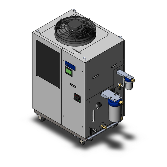
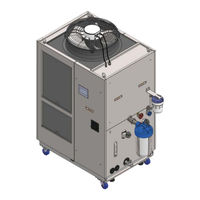
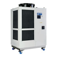
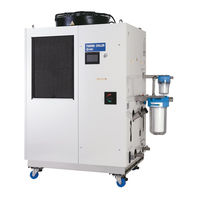
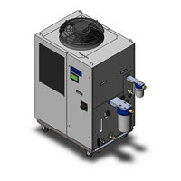
Thermo Chiller
Brand:
SMC Networks
| Category:
Chiller
| Size: 10.15 MB
Table of Contents
Table of Contents
3
Chapter 1 Safety Instructions
9
Before Using the Product
9
Reading the Manual
9
Hazards
10
Level of Hazards
10
Definition of "Serious Injury" and "Minor Injury
10
Product Label
11
Safety Measures
12
Safety Instructions for Use
12
Personal Protective Equipment
12
Emergency Measures
13
Waste Disposal
13
Disposal of Refrigerant and Compressor Oil
13
Disposal of Product
13
Battery
14
Safety Data Sheet(Sds
14
Chapter 2 Name and Function of Parts
17
Name and Function of Parts
17
HRL-A-40 (Air-Cooled Type)
17
HRL-W-40 (Water-Cooled Type)
17
Function of Parts
19
Chapter 3 Transport and Setting up
21
Transport
21
Transportation Using Forklift and Hanging
22
Transportation Using Casters
23
Installation
24
Environment
24
Location
26
Installation and Maintenance Space
28
Installation
29
Electrical Wiring
31
Preparation and Wiring of Power Supply Cable
33
Contact Input/Output Communication Wiring
38
Wiring of the Run/Stop Signal Input
42
Wiring of the Contact Output Signal
44
Wiring of Analog Output Signal
45
Communication Wiring
45
RS-232C Communication Wiring
47
Ethernet Modbus/Tcp Communication Wiring
48
Piping
51
Circulating Fluid Supply
63
Chapter 4 Starting the Product
65
Before Starting
65
Preparation for Start
66
Power Supply
66
Operation Screen (Home Screen)
67
Preparation of the Circulating Fluid Supply to the User's Equipment
68
Operation Start and Stop
70
Setting of Circulating Fluid Temperature
70
Setting of the Pump Operation Mode
71
Starting the Product
71
Stopping the Product
72
Check Items During Startup
73
Adjusting the Circulating Fluid Flow Rate
73
Chapter 5 Display and Setting of Various Functions
75
Basic Operation
75
Touch Panel
75
Basic Operating Instructions
76
Flow Chart of the Operation Screen
78
List of Functions
81
Description of the Screen
82
Home Screen
82
Menu Key
83
Display and Setting of Date and Time
83
Operating Condition Display
83
Current Circulating Fluid Temperature [PV]
84
Circulating Fluid Set Temperature [SP]
84
Circulating Fluid Discharge Pressure [Press PV]
85
Circulating Fluid Flow Rate [Flow PV]
85
Circulating Fluid Flow Rate [DI PV]
85
Operation Mode [MODE]
86
RUN/STOP Display
87
Run/Stop Operation
87
Menu
88
Status Screen
88
Information Screen
90
Alarm Reset
91
Alarm Name
91
Alarm Log Record
92
Display of Alarm/Maintenance Reminder
93
Check Operation Time Screen and Maintenance Reminder
94
Setting the Usage Time of DI Filter
96
Setting of the Usage Time of Dustproof Filter (Only for Air-Cooled Type)
96
Software Version Screen
97
CH1 Setting Screen
97
Temperature Rise/Drop Alarm (AL10/AL11)
98
TEMP READY Alarm (AL12) of TEMP READY Function
100
Offset (TEMP OFFSET) Function
103
Pump Operation Mode
106
Discharge Pressure Alarm (AL18/AL19/AL20)
107
Electric Conductivity and Alarm Setting (AL28)
109
CH2 Setting Screen
110
Temperature Rise/Drop Alarm (AL14/AL15) Setting
111
TEMP READY Alarm (AL16) and TEMP READY Function
112
Offset (TEMP OFFSET) Function
114
Pump Operation Mode
115
Discharge Pressure Alarm (AL21/AL23/AL24/AL26)
116
Electric Conductivity and Alarm Setting (AL27)
117
Function Setting Screen
119
KEY-LOCK, START-UP Operating Method, ANTI-FREEZING and WARMING-UP
120
Continuing Pump Operation
121
Ambient Temperature Alarm (AL35) and Maintenance Alarm (AL36)
124
TEMP out Signal
125
Data Reset
126
Communication Setting Screen
127
Setting for Communication Error (Al34)/Contact Input Signal Detection (AL30 and AL31)
128
Serial Communication Setting
129
Setting of Analog Output Signal
131
Setting of Contact Input Signal Form
131
Setting of Contact Output Signal 1 to 3
133
Setting of Contact Output Signal 4 to 6
134
Ethernet Modbus / TCP Communication Settings
138
How to Set the IP Address
139
Temperature Waveform Screen
140
Chapter 6 Option
143
Option-T2 [CH2 High-Pressure Pump Mounted]
143
Option-T3 [CH2 High-Pressure Pump Mounted]
144
Chapter 7 Alarm Notifications and Troubleshooting
145
Alarm Notification
145
Operation of this Product When an Alarm Occurs
145
Troubleshooting
146
Alarm Contents, Causes, and Troubleshooting
146
Other Errors
149
Chapter 8 Control, Inspection and Cleaning
151
Quality Control of Circulating Fluid and Facility Water
151
Inspection and Cleaning
152
Daily Check
152
Monthly Check
153
Inspection Every 3 Months
154
Inspection Every 6 Months
155
Operation Stop for an Extended Period of Time
156
Discharge of the Circulating Fluid
156
Discharge of the Facility Water (Water-Cooled Type)
159
Replacement of Consumables
160
Replacing Particle Filters
160
Replacing the DI Filter
160
Consumables
163
Chapter 9 Documents
165
Specifications
165
Hrl100/200/300-A-40
165
Hrl100/200-W-40
167
Refrigerant with GWP Reference
169
Communication Specifications
169
Dimensions
170
Hrl100/200-W-40
173
Flow Diagram
174
Cooling Capacity
176
Hrl100-A-40 Ch1
176
Hrl200-A-40 Ch1
176
Hrl300-A-40 Ch1
177
Hrl100/200/300-A-40 Ch2
177
Hrl100-A-40-T2 Ch1
178
Hrl200-A-40-T2 Ch2
178
Hrl300-A-40-T2 Ch1
179
Hrl100/200/300-A-40-T2 Ch2
179
Hrl300-A-40-T3 Ch1
180
Hrl300-A-40-T3 Ch2
180
Hrl100-W-40 Ch1
181
Hrl200-W-40 Ch1
181
Hrl100/200-W-40 Ch2
182
Hrl100-W-40-T2 Ch1
182
Hrl200-W-40-T2 Ch1
183
Hrl100/200-W-40-T2 Ch2
183
Pump Capacity
184
Hrl100-A/W-40 Ch1
184
Hrl200-A/W-40 Ch1
184
Hrl300-A-40 Ch1
185
Hrl-A/W-40 Ch2
185
Hrl100/200/300-A/W-40-T2 Ch1
186
Hrl300-A-40-T3 Ch2
186
Types of Hazard Labels
187
Positions of Danger Warning Label
188
Standards
189
Daily Check Sheetheck Sheet
190
Chapter 10 Product Warranty
192
Advertisement
SMC Networks HRL Series Operation Manual (162 pages)
Thermo Chiller
Brand:
SMC Networks
| Category:
Chiller
| Size: 6.74 MB
Table of Contents
Table of Contents
3
Chapter 1 Safety Instructions
7
Before Using the Product
7
Reading the Manual
7
Hazards
8
Level of Hazards
8
Definition of "Serious Injury" and "Minor Injury
8
Product Label
9
Safety Measures
10
Safety Instructions for Use
10
Personal Protective Equipment
10
Emergency Measures
11
Waste Disposal
11
Disposal of Refrigerant and Compressor Oil
11
Disposal of Product
11
Safety Data Sheet(Sds
12
Chapter 2 Name and Function of Parts
13
Model Number of Product
13
Name and Function of Parts
14
HRL-A-20 (Air Cooled Type)
14
Function of Parts
16
Chapter 3 Transport and Setting up
17
Transport
17
Transportation Using Forklift and Hanging
18
Transportation Using Casters
19
Installation
20
Environment
20
Location
22
Installation and Maintenance Space
23
Installation
24
Electrical Wiring
26
Preparation and Wiring of Power Supply Cable
28
Contact Input/Output Communicatin Wiring
33
Wiring of Run/Stop Signal Input
37
Wiring of Contact Output Signal
39
Wiring of Analog Output Signal
40
Communication Wiring
40
RS-232C Communication Wiring
42
Piping
44
How to Connect to the Drain Port
50
Circulating Fluid Supply
52
Chapter 4 Starting the Product
55
Before Starting
55
Preparation for Start
56
Power Supply
56
Operation Screen (Home Screen)
57
Preparation of Circulating Fluid Supply to User's Equipment
58
Operation Start and Stop
60
Setting of Circulating Fluid Temperature
60
Setting of Pump Operation Mode
61
Starting the Product
61
Stopping the Product
62
Check Items During Startup
63
Adjustment of Circulating Fluid Flow Rate
63
Chapter 5 Display and Setting of Various Functions
65
Basic Operation
65
Touch Panel
65
Basic Operating Instructions
66
Flow Chart of Operation Screen
68
List of Functions
71
Description of Screen
72
Home Screen
72
Menu Key
73
Display and Setting of Date and Time
73
Operating Condition Display
73
Current Circulating Fluid Temperature PV
74
Circulating Fluid Set Temperature SP
74
Circulating Fluid Discharge Pressure Press PV
75
Circulating Fluid Flow Rate Flow PV
75
Circulating Fluid Flow Rate DI PV
75
Independent Pump Operation Pump
76
Operation Mode MODE
76
RUN/STOP Display
76
Run/Stop Operation
77
Menu
78
Status Screen
78
Information Screen
80
Alarm Reset
81
Alarm Name
81
Alarm Log Record
82
Display of Alarm/Maintenance Reminder
83
Check Operation Time Screen and Maintenance Reminder
84
Setting the Usage Time of DI Filter
85
Setting of the Usage Time of Dustproof Filter
85
Software Version Screen
86
CH1 Setting Screen
86
Temperature Rise/Drop Alarm (AL10/AL11)
87
TEMP READY Alarm (AL12) of TEMP READY Function
89
Offset (TEMP OFFSET) Function
92
Pump Operation Mode
95
Discharge Pressure Alarm (AL18/AL19/AL20)
96
CH2 Setting Screen
98
Temperature Rise/Drop Alarm (AL14/AL15) Setting
99
TEMP READY Alarm (AL16) of TEMP READY Function
100
Offset (TEMP OFFSET) Function
102
Pump Operation Mode
103
Discharge Pressure Alarm (AL21/AL23/AL24/AL26)
104
Electric Conductivity and Alarm Setting (AL27)
105
Function Setting Screen
107
Key-Lock, Startup Operating Method, Anti-Freezing and Warming-Up
108
Continuing Pump Operation
109
Ambient Temperature Alarm (AL35) and Maintenance Alarm (AL36)
112
TEMP out Signal
113
Data Reset
114
Communication Setting Screen
115
Setting for Communication Error (Al34)/Contact Input Signal Detection (AL30 and AL31)
116
Serial Communication Setting
117
Setting of Analog Output Signal
119
Setting of Contact Input Signal Form
119
Setting of Contact Output Signal 1 to 3
121
Setting of Contact Output Signal 4 to 6
122
Temperature Waveform Screen
126
Chapter 6 Alarm Notification and Troubleshooting
129
Alarm Notification
129
Operation of this Product When an Alarm Occurs
129
Troubleshooting
130
Alarm Contents, Causes, and Troubleshooting
130
Other Errors
133
Chapter 7 Control, Inspection and Cleaning
135
Quality Control of Circulating Fluid and Facility Water
135
Inspection and Cleaning
136
Daily Check
136
Monthly Check
137
Inspection Every 3 Months
138
Operation Stop for an Extended Period of Time
139
Discharge of the Circulating Fluid
139
Replacement of Consumables
141
Replacing Particle Filters
141
Replacing the DI Filter
142
Consumables
144
Chapter 8 Documents
145
Specifications
145
Hrl100/200/300-A-20
145
Refrigerant with GWP Reference
146
Communication Specifications
146
Dimensions
147
Hrl200-A-20
148
Hrl300-A-20
149
Flow Diagram
150
Cooling Capacity
151
Hrl100-A-20 Ch1
151
Hrl200-A-20 Ch1
151
Hrl300-A-20 Ch1
152
Pump Capacity
153
Hrl100-A-20 Ch1
153
Hrl200-A-20 Ch1
153
Hrl300-A-20 Ch1
154
Hrl-A-20 Ch2
154
Types of Hazard Labels
155
Positions of Danger Warning Label
156
Standards
157
Daily Check Sheetheck Sheet
158
Chapter 9 Product Warranty
159
SMC Networks HRL Series Manual (28 pages)
Circulating fluid temperature controller thermo-chiller
Brand:
SMC Networks
| Category:
Chiller
| Size: 19.3 MB
Table of Contents
Table of Contents
9
How to Order/Specifications
10
Cooling Capacity
11
Pump Capacity
11
Dimensions
12
Parts Description
15
Recommended External Piping Flow
15
Cable Specifications
15
Operation Display Panel
16
Alarm
16
Communication Functions
17
Optional Accessories
20
Cooling Capacity Calculation
21
Required Cooling Capacity Calculation
21
Precautions on Cooling Capacity Calculation
22
Circulating Fluid Typical Physical Property Values
22
Specific Product Precautions
23
Advertisement
Advertisement
Related Products
SMC Networks HRL100-A*-20 Series
SMC Networks HRL200-A*-20 Series
SMC Networks HRL300-A
SMC Networks HRL200-A
SMC Networks HRL200
SMC Networks HRL100-A-40
SMC Networks HRL200-A-40
SMC Networks HRL300-A-40
SMC Networks HRLE090-A-40
SMC Networks HRL400-A-40
SMC Networks Categories
Switch
Control Unit
Controller
Network Router
Wireless Router
More SMC Networks Manuals
Login
Sign In
OR
Sign in with Facebook
Sign in with Google
Upload manual
Upload from disk
Upload from URL