Table of Contents
Advertisement
Advertisement
Table of Contents

Related Manuals for Rain Bird IC System


Summary of Contents for Rain Bird IC System
- Page 1 IC System Design Guide v 2.3 Updated August 2016...
-
Page 2: Table Of Contents
IC System – Product Definitions ........................ Integrated Control Interface (ICI)........................4 Integrated Control Module (ICM) ......................... 5 Integrated Control Surge Device (ICSD) ......................5 Components of the IC Interface (ICI) ......................6 Uninterruptable Power Supply (UPS) ......................7 How the System Works ..........................8 Basic Design Data ............................ -
Page 3: Ic System- Product Definitions
. If there are any questions or specific examples that may not be adequately addressed within this guide, please contact your Rain Bird sales or service manager for additional clarification to aid in the proper design for the specific application. -
Page 4: Integrated Control Interface (Ici)
The Integrated Control Interface (ICI) is the electronic hardware and firmware that accepts commands from the Central Control Software and directs them to the field. The ICI also communicates intelligently with the field in order to update the status back to the Central Control Software. IC System Design Guide, v2.3... -
Page 5: Integrated Control Module (Icm)
ICI interface. The central control software automatically operates the rotors and valves throughout the golf course by activating each individual ICM as needed. If the ICM is installed on Rain Bird electric in-line valves, an ICM valve adapter (ICMA) is required. ICSD The Integrated Control Surge Device (ICSD) provides surge protection for the system in case of lightning strikes. -
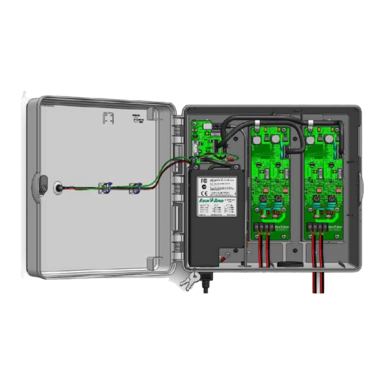
Page 6: Components Of The Ic Interface (Ici)
The CPU Board provides communication between the Central Control Computer and each of the wire paths. Driver Board The Driver Board provides communication between the CPU board and the ICMs in the field. Depending upon the model, there may be one or two Driver Boards in the ICI. IC System Design Guide, v2.3... -
Page 7: Uninterruptable Power Supply (Ups)
Uninterruptable Power Supply (UPS) Rain Bird recommends the use of a UPS to provide battery backup in cases of fluctuating or loss of power to the Integrated Control Interface (ICI). When operated by battery the IC System requires a “pure sine wave” signal and not a modified, square or PWM wave. -
Page 8: How The System Works
How the system works The IC System uses a data transfer method that sends packets of information across a two-wire path. Each ICM has a unique address that allows the central control software to communicate with each ICM individually. The ICM has a unique “Long Address” pre-assigned from the factory that identifies it in the central control software. -
Page 9: Basic Design Data
5. The ICI has a maximum capacity of 3,000 stations when all four (4) wire paths are used on the two (2) Driver Boards. 6. The IC System can be expanded above 3,000 stations with the optional hybrid capability of the central control software. Using the optional hybrid feature, multiple ICIs can be integrated into the system, each with a capacity of 3,000 stations. -
Page 10: System Capacity
** Maximum stations available for each level of software when additional ICIs and Hybrid Software Module are purchased. Flexible Design The IC System was designed to be as flexible as possible to accommodate the future needs of the golf course. -
Page 11: Wire Path
The low power requirements of each ICM ensure that it is easy to design wire paths. There are three considerations when sizing the wire path for an IC System. •... -
Page 12: Wire Sizing Charts
If the chart recommends 12 AWG (4.0 mm ) based on number of units and total length of run of the wire path, then additional upsizing in a long initial run of wire is not necessary. IC System Design Guide, v2.3... -
Page 13: Examples
Although there are multiple branches off of the main Trunk wire, these are not part of the calculation when determining the size of the Trunk wire. Each branch will also be 14 AWG (2.5 mm ) wire. IC System Design Guide, v2.3... - Page 14 25% of the total Trunk wire length. In this example, any branch that is less than 2250 feet (685 meters), 25% of the Trunk wire length, can be installed with 14 AWG (2.5 mm ) wire. IC System Design Guide, v2.3...
-
Page 15: Examples
Although there are multiple branches off of the main Trunk wire, these are not part of the calculation when determining the size of the Trunk wire. Each branch will also be 14 AWG (2.5 mm IC System Design Guide, v2.3... -
Page 16: Grounding
. The system grounding is accomplished through the ICSD surge devices that are installed on the wire path. Rain Bird MSP surge devices are installed on each wire path prior to entering the Integrated Control Interface (ICI) at the central. -
Page 17: Types Of Pipe Networks
Bird looks to the irrigation designer to select the best pipe network layout for the irrigation system design and then apply the IC System wire path on that layout. Each type of pipe network design offers different advantages depending upon the location and size of the irrigation system. There is no preference for the IC System wire path. -
Page 18: Wire Path "Field Fuses
ICM is specifically designed to fail offline by itself and not bring down the wire path when damaged. For this reason, Rain Bird strongly discourages the use of third-party switches on the IC System. Third-party switches are an unnecessary, extra device on the wire path with the potential to act as an additional failure point to be investigated. - Page 19 It is possible to remotely configure an IC interface to communicate via Ethernet or cellular with the irrigation central. This has been done successfully on Rain Bird control systems in a number of locations. Please contact your Rain Bird Golf Distributor or Rain Bird sales manager for additional information.
- Page 20 IC System Design Guide, v2.3...
- Page 21 IC System Design Guide, v2.3...
Need help?
Do you have a question about the IC System and is the answer not in the manual?
Questions and answers