Table of Contents
Advertisement
Assembly and
Commissioning Manual
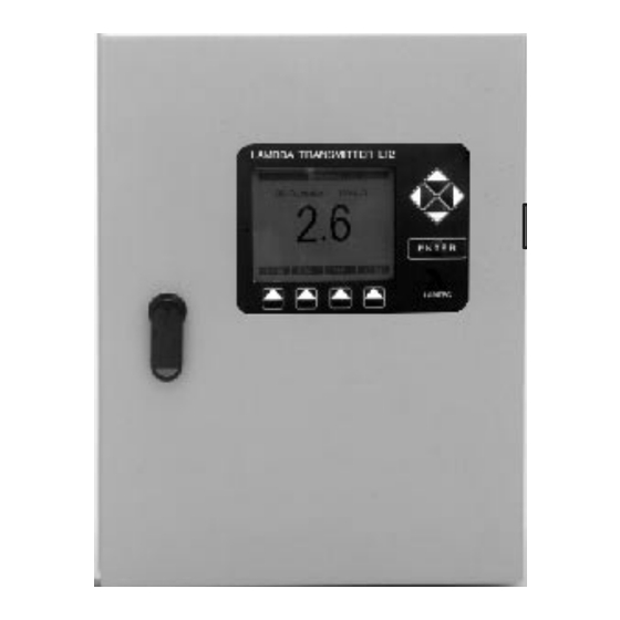
Lambda-
Transmitter LT 2
RS 232
(
Operation
,
servicing
)
Option:
CANopen
Modbus
Profibus DP
Ethernet
Sensors and Systems
for Combustion Engineering
Analogue inputs
and outputs
Digital inputs
and outputs
to other
LAMTEC
devices
FMS / VMS / ETAMATIC
LT 1 / LT 2
Lambda Transmitter LT 2/KS1-DK
Combination Probe KS1-DK
Simultaneous measurement of Oxygen (O
and oxidizing components (CO/H
Combination
probe KS1-DK
Recording
LAMTEC SYSTEM BUS
Digital inputs
and outputs
O
CO/H
Analogue inputs
and outputs
Optional modules
)
2
)
2
2
2
Advertisement
Table of Contents

Related Manuals for Lamtec LT 2


Summary of Contents for Lamtec LT 2
- Page 1 Option: LAMTEC SYSTEM BUS CANopen Modbus Profibus DP Ethernet to other Analogue inputs Digital inputs LAMTEC devices and outputs and outputs FMS / VMS / ETAMATIC Optional modules LT 1 / LT 2 Sensors and Systems for Combustion Engineering...
-
Page 3: Table Of Contents
Necessary components ......................16 Basic design of the LT 2/KS1-DK ................... 17 LT 2/KS1-DK........................... 18 Internal display and control elements of the LT 2/KS1-DK lambda transmitter ..... 20 Display and operating unit ...................... 22 Analogue output........................30 Digital inputs ........................... 31 LAMTEC SYSTEM BUS ...................... - Page 4 Checking/calibrating the KS1-DK combination probe.............70 Checking the LT 2/KS1-DK.....................71 Maintenance ...........................72 Fault Analysis/Trouble-shooting .............. 75 Fault indicator via LED line in the LT 2/KS1-DK ..............75 Warning indicator via LED line in the LT 2/KS1-DK ...............78 Resetting faults/warnings......................82 Spare Parts ....................83 Wearing parts..........................83...
-
Page 5: General Information
LAMTEC GmbH & Co KG is not liable for damages occurring as a result of non- compliance with the above instructions. Compliance with the above instructions shall not entail any extension to the warranty and liability provisions of LAMTEC GmbH &... -
Page 6: Safety Information
2 Safety Information Safety Information The symbols below are used in this Manual as important safety notes for the user. They are located in the sections of the Manual wherever the information is needed. The safety information - and warnings, in particular - must be read and observed. WARNING This draws attention to possible dangers to persons, particularly from electrical equipment. -
Page 7: Proper Use, Conditions For Use
2 Safety Information Proper use, conditions for use The LT 2/KS 1D lambda transmitter is a universal, microprocessor-based measuring device for the direct measurement of the concentration of O2 and flammable, oxidising gas constituents (CO/H ), referred to as CO equivalent ( COe ), in the superstoichiometric range in combustion systems ( l >1 ), in... -
Page 8: Permitted Users
User groups The following three groups of users are permitted to handle the LT 2/KS 1D lambda transmitter: •... -
Page 9: Safety Equipment / Protective Measures
Therefore, always observe the relevant safety notes to prevent damage. Preventive measures to If the LT 2/KS1-DK is employed as a sensor in combination with closed and open- improve operational loop control systems, the plant operator must ensure that a failure or fault in the... -
Page 10: Environmentally Responsible Behaviour, Disposal Instructions
CAUTION! Do not switch off the LT 2/KS1-DK lambda transmitter while the KS1-DK combination probe is still mounted, even if the associated system has been shut down. Residual gases lead to corrosion and may damage system parts. -
Page 11: Introduction
3 Introduction Introduction The LT 2/KS1-DK lambda transmitter is a universal, microprocessor-based measuring device for the simultaneous measurement of the concentration of O and oxidising gas constituents (CO/H ), referred to as CO equivalent ( COe ), most commonly in the exhaust gases of combustion systems in the superstoichiometric range ( l >1 ), in... - Page 12 3 Introduction 3.1.1 KS1-DK combination probe In the version for exhaust gas temperatures up to 450°C The KS1-DK and KS1-DK-E combination probes enable in situ (directly in the exhaust gas), simultaneous measurement of the concentration of O and flammable, oxidising gas constituents (CO/H ), referred to as CO equivalent (COe), in combustion exhaust gases in the superstoichiometric range (l>1).
- Page 13 3 Introduction In ejector version for exhaust gas temperatures up to 1400°C (on request) • With standard GED (stainless steel 1.4571), suitable for exhaust gas temperatures from 400°C...700°C. • With ceramic GED, suitable for exhaust gas temperatures up to 1400°C. •...
- Page 14 3 Introduction 3.1.2 LT 2 lambda transmitter In the version for KS1-DK Two basic versions are available: LT 2/KS1-DK lambda transmitter in IP65 wall- mounted housing • Sheet steel H400 x W300 x D150 mm • With display and operating unit •...
-
Page 15: Theoretical Principles Of Measurement
3 Introduction Theoretical principles of measurement The KS1-DK combination probe basically consists of an electrochemical cell of zirconium dioxide ceramic. It has three electrodes: • -sensitive platinum electrode • CO/H -sensitive electrode of a platinum/precious metal alloy • Platinum reference electrode Probe method of functioning - O -sensitive electrode CO/H electrode... -
Page 16: Probe Method Of Functioning - Co/H
3 Introduction Probe method of functioning - CO/H -sensitive electrode Flammable constituents are, like oxygen molecules, adsorbed on the electrode and diffuse to the “three-phase limit” formed by measuring gas, the electrode and zirconium dioxide. In addition to the Nernst voltage U determined on the basis of the oxygen content, the flammable constituents in the measuring gas also generate an additional direct voltage U... - Page 17 3 Introduction If concentrations of O are higher, more unburned residues (CO/H ) oxidise before the 3-phase limit is reached. The graph below shows the influence of the sensor voltage U as a function of the O content. 1000 at starting point with 0% CO 9,5 % O...
-
Page 18: Technical Description
Flange gasket • Internal/external reference air pump or compressed air connection • LT 2/KS1-DK lambda transmitter in IP65 wall-mounted housing incl. display and operating unit, or • on IP00 mounting plate for installation in control cabinet, without display and operating unit... -
Page 19: Basic Design Of The Lt 2/Ks1-Dk
4 Technical Description Basic design of the LT 2/KS1-DK Semi-automatic calibration system max. 450°C Pos. Pos. Combination probe KS1-DK Pre filter with semi-automatic calibration system Type 650 R 2055 Type 656 R 2030 / R2031 / R2032 Probe connection box (PCB) -
Page 20: Lt 2/Ks1-Dk
4.4.1 In wall-mounted housing The LT 2/KS1-DK lambda transmitter is the data interpreting device for the KS1-DK combination probe. It incorporates all the necessary components for the operation of the KS1-DK combination probe and the evaluation of the measurement signal. - Page 21 4 Technical Description 4.4.2 On mounting pate Type 657 R 1032 Buffer amplifier for Transformer converting the for probe and COe signal from electronics mV into mA (no longer required from January 2007) Fuses Supply voltage commutation AC115V/AC230V NOTE Replace fuse Connection for remote display software (optional...
-
Page 22: Internal Display And Control Elements Of The Lt 2/Ks1-Dk Lambda Transmitter
4 Technical Description Internal display and control elements of the LT 2/KS1-DK lambda transmitter The LT 2/KS1-DK is operated and the measurement values, process status and fault status signals are displayed via the display and operating unit (see section 4.6), or via PC in conjunction with the remote display software. - Page 23 4.5.2 Monitor output The monitor output [terminal 31 (-), 32 (+)] allows a multimeter to be connected, for example. Via the monitor output, the following measurement values can be obtained in situ on the LT 2/KS1-DK: • measurement value •...
-
Page 24: Display And Operating Unit
4 Technical Description Display and operating unit The display and operating unit of the LT 2/KS1-DK consists of an LCD, the cursor keys, the Enter key and the menu keys. • The cursor keys enable you to select measurement values, parameters or functions in the viewing window of the display. - Page 25 4 Technical Description 4.6.1 Menu function When the [meas] key is pressed, the screen switches to a large display of the measurement value, which is selected using the cursor keys (up, down). By pressing the [meas] key several times, you can return to the display of all measurement values. 4.6.2 Menu function When the [cal] menu key is pressed, “Start calibration”...
- Page 26 4 Technical Description 4.6.3 Menu function Opening the [ par ] menu opens the menu for the parameters. The Parameter menu is available to the following access levels: • Operation level • Customer level • Service level (only accessible via password) •...
- Page 27 4 Technical Description 4.6.5 Menu function [ view ] opens the Parameter menu. The functions of the menu bar are as follows: [ exit ] returns to the [ par ] menu function. [ s/l ] changes the display format: Short: Only the number of the parameter and the current value are displayed.
- Page 28 4 Technical Description 4.6.6 Menu function [ change ] allows you to change parameter values. The sub-menu in the menu bar is the same as the [ view ] menu. But unlike this, the parameter to be changed is shown inverted (pale font on dark background).
- Page 29 4 Technical Description 4.6.7 Menu function The [diag] key switches the screen to the display of warnings and faults. You can select individual warnings, faults or limit values using the cursor keys (up, down). NOTE: Limit values are only displayed if they have been activated via the parameters 930/940/950/960 (Service level).
- Page 30 4 Technical Description 4.6.8 Display parameters 970 / 971 / 972 The ***Display*** parameter group is responsible for the display and operating unit for the LT 2/KS1-DK, with the following parameters: • P. 970 Contrast This parameter allows you to adjust the contrast of the display.
- Page 31 4 Technical Description 4.6.10 Entering the customer password The password for Customer level can be assigned individually by the customer. To enter a new password, the Customer access level or higher must be activated. The new password must be entered in parameter 1472, (see figure below). CAUTION! A few seconds after the password is entered, it is accepted by the device and “####”...
-
Page 32: Analogue Output
Lower range limit Parameters 533 / 543 / 553 / 563 Upper range limit Can be retrofitted at any time by means of plug-in cards on the LT 2/KS1-DK processor board (max. 4) Type 6 57 R 0050 non-floating Type 6 57 R 0051 floating, maximum possible potential difference ± 20 V (only... -
Page 33: Digital Inputs
4 Technical Description Digital inputs Eight digital inputs can be configured for the LT 2/KS1-DK lambda transmitter. Depending on the supplied voltage, the digital inputs take on the setting High (supplied voltage 24 V) or Low (input open or supplied voltage 0 V). - Page 34 4 Technical Description 4.8.1 Parameters of digital inputs Idle state Here you can set the idle state of the digital input. If the state differs from the one set Parameters: here, the actions predefined for the functions (A, B, C, D) are executed. If Diagnostic 1170/1180/1190/1200/ mode is set here, the functions (A, B, C, D) can be initiated for the corresponding 1210/1220/1230/1240...
-
Page 35: Lamtec System Bus
4 Technical Description LAMTEC SYSTEM BUS NOTE: Data transmission in the LT 2 via the LAMTEC SYSTEM BUS only functions if the device is set to “MEASUREMENT” and is not in “MAINTENANCE MODE” or “FAULT”. When communication is taking place correctly, the two LEDs 1 and 2 flash. -
Page 36: Rs 232 Interface
4 Technical Description 4.10 RS 232 interface Device address 1 9600 bauds Parity none 4.11 Cold start delay This function is used to suppress false measurement values while the probe is warming up. A cold start delay is always activated after “Power off” and probe replacement. -
Page 37: Optional Extras
• Heating for wall mounting case 4.12.1 Remote display software PC software for configuring the LT 2/KS1-DK as an alternative to the display and operating unit, and for saving and restoring the data record. • Remote display software incl. interface module RS 232 for PC Type 6 57 R 1101 •... - Page 38 Type 6 57 R 0895K NOTE: Since three of the four analogue inputs are assigned in the LT 2 / KS1 DK, the differential pressure sensor, which monitors the reference air, is removed and replaced with a flow meter with limit value signal. This signal is fed to a digital input and monitored as the warning “No reference air”.
- Page 39 4 Technical Description Electrical connection of the LT2/KS1-DK with efficiency calculation Lambda-Transmitter LT 2 Lambda-Transmitter LT 2/ KS1 -DK / KS1 -DK with efficiency calculation * Module 4 Output 4 80...100% efficiency = 4...20mA Analoge outputs (Option) 0/4…20 mA Output 3...
- Page 40 4 Technical Description Lambda-Transmitter LT 2/KS1 -DK Lambda-Transmitter LT 2/KS1 -DK with efficiency calculation CAN Low CAN High LAMTEC SYSTEM BUS LAMTEC SYSTEM BUS not con. (CAN-BUS) (floating) not con. CAN-GND Input 8 Digital inputs Fuel 4 Input 7 24 V, ca. 6 mA...
- Page 41 4.12.4 Load-dependent, fuel-specific limit curves (optional extra) Type 6 57 R 0920 The load rating (burner load) or another measured variable is activated via analogue input 4 or the LAMTEC SYSTEM BUS. Instead of fixed limit values, fuel-specific curves with two to maximum 18 interpolation points can be entered.
- Page 42 4 Technical Description 4.12.7 Digital outputs Digital output 1 (standard): Included as standard in LT 2/KS1-DK basic electronics via internal relay (1 change-over contact) (terminals 1, 2 and 3, also see 10.3). Switching capacity 230VAC / 2A and 42VDC / 3A...
- Page 43 4 Technical Description Functions A,B,C,D The four functions have virtually the same structure, and an operating state can act as Parameters: 1031 to 1034 a switching criterion. If a limit value (LV 1-4) is selected as a switching criterion, the 1041 to 1044 output switches when the limit value output is enabled.
- Page 44 For the systems • Profibus DP (Siemens) Type 6 63 R 0401LT NOTE: PROFIBUS parameters in LT 2: P1300 – P1318. See separate publication, “Profibus for LT”. Profibus module Electrical connection to LAMTEC SYSTEM BUS via terminal bar. See section 10.4.
-
Page 45: Limit Values
4 Technical Description 4.13 Limit values Measurement data can be monitored with the aid of the limit values. The LT 2/KS1-DK is equipped as standard with four fixed limit values, which can be freely configured. Limit values (factory setting) •... - Page 46 A value calculated from the O actual value or an analogue input is employed as the value: reference value. In the LT 2/KS1-DK lambda transmitter, one of 12 different available reference values may be selected. Configuration of the analogue values to be calculated.
- Page 47 4 Technical Description Reset mode (param. 935/945/955/965) If the limit value was enabled by the reference value being undershot or exceeded, this parameter describes the mode for resetting the limit value. There are three possible ways of doing this: Automatic: If the monitored reference value changes so that it reaches the GOOD state once more, the limit value output is automatically reset.
- Page 48 4 Technical Description Display and reset of limit values The current state of the limit values and resetting them takes place using the display in the Limit Values group. Parameters: 910 ... 914 The parameters Limit Value 1, Limit Value 2, Limit Value 3 and Limit Value 4 indicate the current settings and state of the limit values.
- Page 49 4 Technical Description Display of excess/undershot limit values The limit values are displayed by means of the softkey designations. When limit value parameter 930/940/950/960 is activated in the “Service” access level, LV1, LV2, LV3 and LV4 appear on the display, depending on which limit value is currently active. Exceeded or undershot limits are displayed as follows: •...
-
Page 50: Analogue Inputs
4 Technical Description 4.14 Analogue inputs Four analogue inputs via plug-in cards on the LT 2/KS1-DK basic electronics. Freely configurable using the display and operating unit or remote display software, parameter groups 570 to 609. • From January 2007 Analogue input card for voltage -200...1000mV... -
Page 51: Device Configuration And Factory Settings
This number is located on the inside of the door of the housing, or on the side in the case of the LT 2/KS1-DK for panel installation. The configuration number has 17 characters and is formulated according to the following code:... - Page 52 4 Technical Description Input d: Analogue inputs 1 2 3 4 0 → Not assigned 1 → Potentiometer 1kΩ 2 → Current 0/4...20 mA 3 → Three-point step (TPS) 4 → Pulse input (Namur) 5 → Temperature input PT 100 range 0…320°C 6 →...
-
Page 53: Installation
Ambient temperature Operation: - 20 °C to + 60 °C Transport and storage - 40 °C to + 85 °C NOTE: Cold electronics = good electronics! This maxim is crucial when determining the installation location for the LT 2/KS1-DK lambda transmitter. - Page 54 5 Installation 5.2.1 LT 2/KS1-DK wall-mounted housing Mount the LT 2/KS1-DK lambda transmitter in a suitable location. For electrical connections and the probe connection, see below. Ensure a suitable spot for wall mounting. Ensure that the wall has a sufficient load- carrying capacity and that the measuring system is easily accessible.
- Page 55 5 Installation 5.2.2 LT 2/KS1-DK mounting plate For installation in the control cabinet (protection class IP00). Ensure sufficient ventilation, provide forced ventilation if necessary. Internal control cabinet temperature max. 60°C. For electrical connections and the probe connection, see below. For electrical connection, see section 10.3.
- Page 56 Take care to ensure that cable routing and screening confirms to regulations. Probe connection: The signal line of the LT 2/KS1-DK, terminals 12, 33 and 34, must not be routed together with mains cables, particularly cables of frequency converters for speed control.
-
Page 57: Installing The Probe
5 Installation Installing the probe CAUTION: The first commissioning / first calibration must be carried out in environment temperatures of -20...+40°C with air (offset calibration). If this should not be ensured in the inserted condition, the first caliration of the probe must be carried out in developed condition and may be inserted thereafter. - Page 58 5 Installation • Connect the probe electrically (wiring diagram chapter 10.3) • Connect the probe pneumatically (connecting diagram chapter 10.4) NOTE: In the PCB of the probe there is a shut-off plug valve, Which must be opened uring calibration with compressed air or test gas. Should be the probe installed in a inaccessibly location, a additional shut-off plug valve can be installed in the near of the LT2.
-
Page 59: Commissioning / Shutdown
6 Commissioning / Shutdown Commissioning / Shutdown The commissioning relates to the software version 1V52 in the LT2, recognizeable at the indentification plate of the LT2. Switch on measurement • Switch on the LT2 Maintenance switch S1 - Maintenance • You can switch to maintenance either using the display and operating unit under mode off “diag”... -
Page 60: Setting The Cell Internal Resistance R
6 Commissioning / Shutdown 6.1.1 Possible warning / faults Warning “Internal resistance of probe 1 too high” Fault “Probe broken wire/faulty probe” • Trigger of the Warning: The internal cell resistance has the limit of 200 Ohm exceeded (in mode “MEASURE”) •... -
Page 61: Setting The Reference Air Quantity
Type 657 R 1061. This pump unit cannot be retrofitted in the LT 2 housing NOTE: The reference air is monitored continuously by a differential pressure sensor, which is installed in the probe connection box of the KS1-DK. -
Page 62: Calibration Of The Probe Ks1-Dk Via Menu Function
6 Commissioning / Shutdown Calibration of the probe KS1-DK via menu function Note: The pressure increase of the calibration with compressed air or testgas is monitored by a absolut pressure sensor. Befor starting calibration, the value of the absolute pressure must be adjusted to the actuell environment pressure. Via a zero point offset in parameter 412 the value of the absolut pressure can be increased or decreased. - Page 63 6 Commissioning / Shutdown 6.4.1 Offset calibration of both sensors on ambient air The first commissioning / first calibration must be carried out in environment temperatures of -20...+40°C with air (offset calibration). If this should not be ensured in the inserted condition, the first caliration of the probe must be carried out in developed condition and may be inserted thereafter.
- Page 64 6 Commissioning / Shutdown 6.4.2 Offset calibration of both sensors with compressed air Uring offset calibration compressed air air the • value will be calibrated to 21% • U-COe voltage will be calibrated to “0” NOTE: Offset calibration on ambient air only works with O2 values > 18%. For offset calibration, compressed air with a pre-pressure of 0,3bar must be connected to the “Test gas”...
- Page 65 6 Commissioning / Shutdown Possible warning / faults Offset voltage outside the limits Probe voltage U-O < -20mV • Trigger of the warning: - Probe voltage U-O in ambient air is outside the range of -20…+20mV • Resolution: - Probe is not in ambient air - Reverse polarity swap probe connection terminals 33-34 - Change the probe / sensor D-P offset calibration too low, not enough gas (compressed air)
- Page 66 6 Commissioning / Shutdown 6.4.3 Calibration of the O value with reference measurement Alternatively, calibration may also be performed with test gas. NOTE: During reference measurement, take into consideration whether the measuring device is measuring wet or dry. In devices with an upstream measuring gas cooler, the measurement is always dry.
- Page 67 6 Commissioning / Shutdown 6.4.4 calibration with test gas Connect test gas at the hose connector “test gas” of the PCB, with a prepressure of 0,3bar. Example for test gas: 3 Vol.% O in N NOTE: The calibration/check with O2- test gas only works with O2 values < 18%. When you press the [cal] menu key, “Start calibration”...
-
Page 68: Ending Calibration
6 Commissioning / Shutdown 6.4.5 CO calibration with test gas Connect test gas at the hose connector “test gas” of the PCB, with a prepressure of 0,3bar. Example for test gas: 3 Vol.% O , 100ppm CO, 100ppm H , in N A test gas CO in N is not suitable for calibration. -
Page 69: Test Report
6 Commissioning / Shutdown Test report A test report is supplied with each probe. It is therefore possible to compare the current measurement values with the values from the test stand. O2-sensor temperature 953 Kelvin... -
Page 70: Probe Certificate
6 Commissioning / Shutdown Probe certificate Every probe comes with a passport, which must be filled out during commissioning. The probe passport must always be enclosed in the case of complaints and repairs. NOTE: The settlement of problems on the basis of goodwill requires the submission of the passport. -
Page 71: Setting Service Warnings
6 Commissioning / Shutdown Setting service warnings Service warnings 1 and 2 draw attention to the need for regular servicing. The plant operator can define service warnings as required, e.g. Service warning 1 → Check probe • Service warning 2 → Remove and clean probe •... -
Page 72: Service And Maintenance
7 Service and Maintenance Service and Maintenance If the boiler is to be wet-cleaned, please note the following: Only carry out wet cleaning after the probe has been removed. If wet cleaning is performed with the probe installed, it will be damaged. Trouble-free operation is then no longer possible. -
Page 73: Checking The Lt 2/Ks1-Dk
7 Service and Maintenance Checking the LT 2/KS1-DK 7.2.1 Checking the measurement input of the LT2/KS1-D Connect a digital voltmeter to terminals 33 (-) and 34 (+) parallel to the probe. Compare the measured O voltage with the displayed probe voltage (U-O2). -
Page 74: Maintenance
7 Service and Maintenance Maintenance Due to the extensive self-diagnosis, the LT2/KS1-DK measurement system is largely maintenance-free. Maintenance is restricted to calibration and, when necessary, cleaning the preliminary filter from dust and other deposits, and the replacement of the measuring element at the given intervals. 7.3.1 Checking the measurement Check the measurement monthly, quarterly or six-monthly, depending on the... - Page 75 7 Service and Maintenance 7.3.3 Cleaning the sintered metal preliminary filter Cleaning the filter is only necessary if permeability is impaired. In this case, one of the two following error messages is displayed: “Delta-P offset calibration too high, dirty filter” “Delta-P offset calibration insufficient, not enough gas”...
- Page 76 7 Service and Maintenance element pieces description item-no. material 1 metal O-ring 650 P 2057 Inconell 600 1 metal O-ring 650 P 2058 Inconell 600 1 CO/H2 sensor incl. adapter 656 P 2030 ZrO2-ceramic 1 filter 650 P 2055 SIKA H 20 6 hex-nut 650 P 2066 1.4571...
-
Page 77: Fault Analysis/Trouble-Shooting
Via remote display software (optional extra) • Indication via LED line, LEDs 7 to 12, on the processor board in the LT 2/KS1-DK Fault indicator via LED line in the LT 2/KS1-DK Indication via LED line, LEDs 7 to 12, LED 12 flashes (faults flash) - Page 78 8 Fault Analysis/Trouble-shooting 8.1.3 Probe broken wire/faulty probe This message appears if the AC internal resistance (R ) of the ZrO measuring cell exceeds the permitted limit value of 300 Ω in measurement mode. The warning “Internal resistance too high” generally appears before or after the above message. •...
- Page 79 8 Fault Analysis/Trouble-shooting 8.1.7 No reference air (can be output as a warning via P395, initiation time 1 hour) This fault also appears if the reference air is monitored by a flow meter with limit transducer (e.g. with the efficiency calculation optional extra 657R0895K, see section 4.12.2) The reference air does not reach the quantity required for flowing around the reference electrode.
-
Page 80: Warning Indicator Via Led Line In The Lt 2/Ks1-Dk
Fault in power pack electronics → replace Checking the LT 2K electronics: Measure the alternating voltage over terminals 33-34 of the LT 2 using a multimeter. The display in mV roughly corresponds to the display of half the AC internal resistance... - Page 81 8 Fault Analysis/Trouble-shooting 8.2.2 Offset voltage outside the limits An impermissible voltage U-O was discovered during offset calibration. Check whether the O measuring cell has been supplied with air. Sufficient flow of compressed air/instrument air Pressure rise greater than 1...2 mbar; see 6.1.2 Cracked filter insert? If OK, check the probe voltage U-O in air.
- Page 82 8 Fault Analysis/Trouble-shooting 8.2.6 D-P test gas calibration too low, not enough gas Inadequate rise in pressure in preliminary filter during test calibration (<0.5mbar). Possible causes: There is no test gas at the test gas connection of the probe, or inadequate pre-pressure (0.3bar) The shut-off plug valve in the PCB is not open.
- Page 83 8 Fault Analysis/Trouble-shooting 8.2.11 Analogue outputs configuration error Analogue outputs are parameterised that cannot physically be found. Check parameters 539, 549, 559, 569 and 530, 540, 550,560 and compare with the inserted cards. If necessary, replace analogue output cards and/or the processor board. 8.2.12 Service warning 1 / service warning 2 The service warning draws attention to the need for regular servicing.
-
Page 84: Resetting Faults/Warnings
8 Fault Analysis/Trouble-shooting Resetting faults/warnings • Menu-guided via “diag” in the display and operating unit (optional extra) • Menu-guided via “Status” using remote display software The [diag] key switches the screen to the display of warnings and faults. You can select individual warnings, faults or limit values using the cursor keys (up, down). -
Page 85: Spare Parts
9 Spare Parts Spare Parts Below is a list of the relevant spare parts. We recommend that you stock up on wearing parts. The stocking of spare parts with footnote is a matter for your own judgement. The stocking of spare parts with footnote only makes sense if the measurement system is equipped with the optional extra in question. -
Page 86: Spare Parts
9 Spare Parts Spare parts Probe KS1-DK Replacement probe complete, average service life approx. 2...5 years (depending on fuel) for measuring gas temperatures up to 450°C Length 500 mm Type 6 56 R 2030 Replacement probe complete, average service life approx. 2...5 years (depending on fuel) for measuring gas temperatures up to 450°C Length 1000 mm... - Page 87 Analogue output card 0/4...20 mA; 0...10 V floating, LT2 Max. potential difference ± 20 V Type 6 57 R 0051 Analogue input card LT1/LT 2 potentiometer 1...5 kΩ LT2 Type 6 57 P 6000 Analogue input card 0/4...20 mA Type 6 63 P 6001 Analogue input card 0/2...10 V LT2...
-
Page 88: Appendix
10 Appendix Appendix 10.1 Technical data of the LT 2/KS1-DK lambda transmitter Version: Wall-mounted housing Wall-mounted housing Mounting pate Type 657 R 1028 with reference air Type 657 R 1032 pump Type 657 R 1060 Housing: Sheet steel, powder-coated Electrogalvanized sheet... - Page 89 4...20 mA, Output 2 0…1000ppm 4…20mA Analogue input: 2 Optional Via plug-in cards on the LT 2/KS1-DK power pack electronics • Analogue input card voltage -200…+1000mV 6 57 P 0660 • Analogue input card potentiometer 1...5 kΩ 6 57 P 6000 •...
- Page 90 10 Appendix Digital outputs: 1 as standard Relay output (collective fault indicator 0...230 V AC, 4A / 0... 42 V DC, 3A Optional extra: Relay module with 6 relays (1 changeover switch) Switching capacity 0...230 V AC, 4A / 0... 48 V DC, 3A 657 R 0857 Configurable as desired for process status, status and limit value signals Digital inputs:...
-
Page 91: Technical Data Of The Ks1-Dk Combination Probe
10 Appendix 10.2 Technical data of the KS1-DK combination probe Measuring range: 0...18 vol. % O2 with limitation 0...21 vol. % O COe: 0...1000ppm COe Measurement accuracy: O2: ± 10 % of measurement value No better than ± 0.3 vol. % O CO: ±... -
Page 92: Electrical Connection
10 Appendix 10.3 Electrical connection Lambda-Transmitter LT 2/ KS1 -DK / KS1 -DK Lambda-Transmitter LT 2 * Module 4 Output 4 not connected Analoge outputs 0/4…20 mA * Module 3 Output 3 not connected 0/2…10 V (Option) Output 2 0...1000ppm COe = 4...20mA... - Page 93 10 Appendix Lambda-Transmitter LT 2/KS1 -DK Lambda-Transmitter LT 2/KS1 -DK CAN Low CAN High LAMTEC SYSTEM BUS LAMTEC SYSTEM BUS not con. (CAN-BUS) (floating) not con. CAN-GND Input 8 Digital inputs Fuel 4 Input 7 24 V, ca. 6 mA...
- Page 94 10 Appendix 10.3.1 Relay module for digital outputs (optional extra) Lambda Transmitter LT 2/KS 1DK Relay Module 660 R 0857 Terminal strip x2 Output 7 Output 6 Relay- outputs Output 5 Max. 230 VAC/4A Output 4 48VDC/3A Output 3 Output 2...
-
Page 95: Pneumatic Connection
10 Appendix 10.4 Pneumatic connection Probe Connection Box after releasing an automatic offset calibration or a calibration with Testgas, set the increase of the difference pressure (dp) with the throttle to 2...4 mbar. Throttle for Testgas to the probe Set difference pressure to 2...4 mbar Shut off plug... -
Page 96: Electrical Connection To Field Bus Module
The reference air must be always connected and be opened. 10.5 Electrical connection to field bus module LT2/KS 1DK ENTER with termination resistor for LSB LAMTEC SYSTEM BUS PB X1 PB X2 5 6 7 8 9 Profibus DP Profibus DP... -
Page 97: Fuses
“heating for wall mounting case” 0.4A slow-blow Probe measurement electronics 1A slow-blow 12 V for display background illumination ± 5 V supply for processor board 1.25A slow-blow 4A slow-blow Probe heater and 24 V supply 0.315A slow-blow LAMTEC SYSTEM BUS... -
Page 98: Jumpers
10 Appendix 10.7 Jumpers LAMTEC SYSTEM BUS BR101 on mainboard: Selection of LSB termination resistor : 1-2 disable 2-3 enable BR12 and BR13 on processor board: to position “C” Digital inputs: BR106, 107: Setting 1-2: Digital inputs based on device potential. -
Page 99: Dimension Drawing Of Ks1-Dk Combination Probe
10 Appendix 10.8 Dimension drawing of KS1-DK combination probe element pieces description item number material Probe head 650 P 2055 1.4571 Reception tube with housing 650 P 2050...2052 1.4571 Probe connection box (PCB) 656 P 2034…2054 Die-cast AL KS 1D probe 656 P 2030…2032 Filter insert 650 R 2055... -
Page 100: Dimension Drawing Of Lt 2/Ks1-Dk In Wall-Mounted Housing
10 Appendix 10.9 Dimension drawing of LT 2/KS1-DK in wall-mounted housing Type 657 R 1028 without pump for reference air LAMBDA TRANSMITTER Type 657 R 1060 with integ. pump for reference air LAMBDA TRANSMITTER... -
Page 101: Dimension Drawing Of Lt 2/Ks1-Dk On Mounting Plate
10 Appendix 10.10 Dimension drawing of LT 2/KS1-DK on mounting plate... -
Page 102: Dimension Drawing Of Display And Operating Unit For Panel Installation
10 Appendix 10.11 Dimension drawing of display and operating unit for panel installation LAMBDA TRANSMITTER LT2 REMOTE Tafelausschnitt / panel cutout / Découpe panneau 276x135mm... -
Page 103: Wet/Dry Measurement - Deviation, Conversion Table
10 Appendix 10.12 Wet/dry measurement – deviation, conversion table dry ) O % ( = O (wet) + Natural gas Oil (CH ) Theoretical maximum deviations between wet/dry measurement of O concentration with natural gas (CH ) or oil (CH ) as fuel (w et) (d ry) Gas Oil... -
Page 104: Ec Declaration Of Conformity
Feuerungen GmbH & Co KG Address: Impexstraße 5, 69190 Walldorf, Germany Product name: LT 2/KS1-DK lambda transmitter in wall-mounted housing LT 2/KS1-DK on mounting plate incl. all optional extras Type 657R1028, 657R1032 The named product conforms to the stipulations of the following European Directives:... - Page 105 LAMTEC Meß- und Regeltechnik LAMTEC Leipzig GmbH & Co KG Presented by: für Feuerungen GmbH & Co KG Impexstraße 5 Schlesierstraße 55 D-69190 Walldorf D-04299 Leipzig Tel. (+49) 06227 6052-0 Tel. (+49) 0341 863294-00 Fax (+49) 06227 6052-57 Fax (+49) 0341 863294-10 Internet: http://www.lamtec.de...
Need help?
Do you have a question about the LT 2 and is the answer not in the manual?
Questions and answers