
Related Manuals for Lamtec LT3-F


Summary of Contents for Lamtec LT3-F
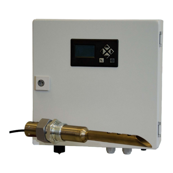
- Page 1 Quick Reference for Endusers Lambda Transmitter LT3-F Combination Probe KS1D Application only in Connection with BT300/ETAMATIC/FMS/VMS to CO/O -Control Sensors and Systems for Combustion Technology www.lamtec.de...
-
Page 3: Table Of Contents
Table of Contents Table of Contents Important Information about the Manual ........7 Validity of these Instructions. - Page 4 Table of Contents 6.5.5 Display ............47 6.5.6 Limit Values .
- Page 5 13.1 LT3-F spare parts........
- Page 6 Important Information about the Manual Validity of these Instructions This manual describe the Lambda Transmitter LT3-F with all required components. The infor- mation in this document applies to the software version 1.0.0.0. If you utilise a different ver- sion, this can lead to other effects to your device than those described in this manual.
-
Page 7: Important Information About The Manual
Important Information about the Manual Information on Using this Operating Manual NOTICE Before starting work, you absolutely must read these instructions! Carefully observe all warning notes! They contain important data and information, the compliance with which will ensure the func- tion of the device and, in turn, reliable measurement results. -
Page 8: General Safety Instructions
General Safety Instructions General Safety Instructions Classification of the Safety Instructions and Warnings The following symbols are used in this document to draw the user's attention to important safe- ty information. They are located at points where the information is required. It is essential that the safety information is observed and followed, and that applies, in particular, to the warnings. -
Page 9: Proper Use - Conditions Of Use
General Safety Instructions Proper Use - Conditions of Use Operation The LT3-F lambda transmitter is an electronic data interpreting device which is used in con- junction with the KS1D combination probe for the continuous measurement of the O concen- tration and the oxidising components (CO/H ) in non-combustible gases in the superstoichiometric area. -
Page 10: Permissible Users
User groups For the handling of the lambda transmitter LT3-F, three user groups are required: • Service technicians of LAMTEC or its OEM customers and/or trained customer personnel: Qualified technicians/engineers ... -
Page 11: Safety Equipment/Safety Measures
To avoid damage, always observe the respective security notices. Preventive measures for improving operating safety If the LT3-F is used in conjunction with control and steering technology, the operator must en- sure that any breakdown or failure of the LT3-F device does not cause inadmissible damage or dangerous operating states. - Page 12 NOTICE Do not switch off the LT3-F Lambda Transmitter as long as the KS1D combination probe is mounted. Not even if the associated plant has been brought to a standstill. Residual gases will cause corrosion and could damage the probe.
-
Page 13: Product Description
Product Description Product Description Applications The LT3-F lambda transmitter has been developed to use in conjunction with the KS1D com- bination probe for the simultaneous measurement of the O concentration and oxidising com- ponents (CO/H ), displayed as CO equivalents (CO ), usually in the flue gases from combustion systems in the superstoichiometric area (>1). -
Page 14: Declaration Of Conformity
Product Description Declaration of Conformity... - Page 15 Product Description...
- Page 16 Mounting and Functions Mounting and Functions Designs and Accessories of the KS1D Combination Probe The KS1D combination probe permits a simultaneous measurement of the O concentration and combustible, oxidising gas components (CO/H ) displayed as ), in the flue gases from combustion systems in the superstoichiometric area CO equivalent (CO (>1) in situ (directly in the flue gas).
-
Page 17: Mounting And Functions
For distances > 2 m, extension cables in lengths of 2 m and 5 m are available. NOTICE The maximum distance between LT3-F and combination probe KS1D may not exceed 10 m. With longer distances the approval of the system for continuous operation expires. -
Page 18: Display And Operational Controls
Display and Operational Controls Display and Operational Controls To display and operate LT3-F, the user interface is integrated into the front door of LT3-F (in- cluded in the standard scope of supply). Functions: • Reading of the O and CO measured values •... -
Page 19: Operation
Display and Operational Controls Operation Using the arrow keys you can navigate within the menus. In the process, move the keys to the right or left by one to make a selection. ENTER ENTER takes you to menu entries or to the edit mode in the case of selected pa- rameters or values. -
Page 20: Information Menu Structure
Display and Operational Controls 5.2.2 Information Menu Structure 5.2.3 Calibration Menu Structure... -
Page 21: Settings Menu Structure
Display and Operational Controls 5.2.4 Settings Menu Structure... -
Page 22: Status Line
Display and Operational Controls Status Line The status line contains information about LT3-F, including the device family. Description status line: Active fault/warning Operating mode OK Heat-up (cold start) Status of limit values 1-4 Active limit value not triggered Non-active limit value (off) -
Page 23: Main Menu
Display and Operational Controls Main Menu Main display Main menu The following values are displayed: • value, resolution 0.1% • value (recommended 1,000 ppm), resolution 1 ppm • Probe signal dynamics • CO edge signal reached/exceeded The factory-set reaction threshold lies at 40%. The display shows whether the reaction thresh- old is reached. -
Page 24: Main Menu - Password Entry
Display and Operational Controls 5.4.1 Main Menu - Password Entry... -
Page 25: Main Menu - Information
Display and Operational Controls 5.4.2 Main Menu - Information Meaning of the symbols: Measured values and probe data Fault/warning history Software version of LT3-F and display CRC checksums Serial number Manual reset of the limit values if they are set to manual reset... -
Page 26: Main Menu - Calibration
Display and Operational Controls 5.4.3 Main Menu - Calibration Meaning of the symbols: Required access level Offset of calibration to 21% O (air calibra- Without tion) calibration At least 1 (Customer) or higher calibration At least 1 (Customer) or higher Fuel changeover At least 1 (Customer) or higher... -
Page 27: Main Menu - Settings
Display and Operational Controls 5.4.4 Main Menu - Settings Meaning of the symbols: Required access level Maintenance mode Without Filter time of the measured values Without Analogue outputs At least 1 (Customer) or higher Triggering of probe replacement At least 1 (Customer) or higher trigger threshold At least 2 (Service) Display parameters... - Page 28 NOTICE Before commissioning, the KS1D combination probe and all alarm/signal outputs are connect- ed, as described in Chapter 6.2 Installation in these operating instructions, to the LT3-F Lamb- da Transmitter. WARNING! Before actuating the main switch for the voltage supply, ensure all housings (evalua-...
-
Page 29: Commissioning
A9xxx, up from November for FMS/VMS 2011 When MODBUS connection RTU for FMS/VMS: M9xxx, up from April 2015 When MODBUS connection TCP for FMS/VMS: E9xxx, up from June 2011 If you have any questions, please contact support@lamtec.de or phone +49 6227 605233. -
Page 30: Installation
10 kg. NOTICE The maximum distance between LT3-F and combination probe KS1D may not exceed 10 m. With longer distances the approval of the system for continuous operation expires. For distances longer than 10 m the risk of EMC increases. -
Page 31: Enter The Password For The Access Level
Commissioning 6.3.1 Enter the Password for the Access Level In the main menu PASSWORD ENTRY select Enter password via ENTER Access level 1: Customer Level Factory setting: 0000 – access to customer functions only Customers can change the password for access level 1. For details ask the burner manufacturer/supplier Access level 2: Service level... -
Page 32: Activate/Deactivate Maintenance Mode
Commissioning 6.3.2 Activate/deactivate Maintenance Mode In maintenance mode, the majority of test routines are disabled. It is advantageous to activate the maintenance mode during probe calibration. Substitute values can be given as an output during active maintenance mode. In the main SETTINGS menu, select In the MAINTENANCE MODE settings, select Menu 460 ACTIVATE/DEACTIVATE MAIN-... - Page 33 Commissioning Wait for transmission end indication. Return to the SETTINGS menu with the BACK and repeat the procedure. In case of cancelling or timeout, this display appears. Return to the SETTINGS menu with the BACK • The symbol appears in the status line. •...
-
Page 34: Response Of The Internal Resistance Regulation
Commissioning 6.3.3 Response of the Internal Resistance Regulation The internal ceramic resistance between the reference and O electrodes (R ) is a func- tion of the sensor temperature, which is constantly regulated for a perfect function of the probe. NOTICE The optimum operating point of the KS1D probe lies at a R of about 20... -
Page 35: Premature Cold Start Termination
Commissioning 6.3.4 Premature Cold Start Termination Occasionally, it might be necessary to terminate the COLD START prematurely, e.g., after a short-term power failure, but not before a minimum waiting period of 120 seconds has expired. NOTICE A premature cold start termination leads directly into measurement operation without an additional prompt. -
Page 36: Reading The Measured Values
Commissioning 6.3.5 Reading the Measured Values In the main menu, select the INFORMATION menu with In the INFORMATION menu, select meas- ured values and probe data with In measured values and probe data, select: Display of the O measured values Display of the CO measured values Display of the R... - Page 37 Commissioning The R internal probe resistance values lie between 15 ... 25 . Display of whether the internal probe resistance regulation is active! Display of the current heating capacity S Display of the setpoint value for the internal resistance regulation. -CO: Evaluates the cross-talk response between the O2 and CO electrodes.
-
Page 38: Calibrating The Probe
Commissioning Calibrating the Probe A correct and regular probe calibration increases measuring precision. The probes can be calibrated by • reference measurement or • test gas For calibration using a reference measurement, an flue gas analyser is required. The probes can then be calibrated when installed / whilst combustion is taking place. -
Page 39: Offset Calibration
Commissioning 6.4.1 Offset Calibration value is equivalent to 20 (see chapter 6.3.5 Before offset calibration, check whether Rki O Reading the Measured Values). Otherwise, proceed as described in chapter 6.3.3 Response of the Internal Resistance Reg- ulation Also check the probe voltage U-O . - Page 40 Commissioning Selecting with the cursor key ENTER triggers an offset calibration. Within 10 s, confirm the setting with ENTER otherwise the value is not assumed. The U-O value stabilises to values between +10 ... -20 mV. The R internal probe resistance values lie between 15 ...
-
Page 41: Calibrating The O 2 Electrode
Commissioning 6.4.2 Calibrating the O Electrode • Activate Maintenance mode. NOTICE Access level 1 or 2 required! NOTICE When calibrating the O electrode in CO containing flue gas the O2 sensors’ Kelvin value moves outside the permissible range (< 800 ... >1200 K). The warning WH004 or WH104 is indicated ... -
Page 42: Perform A Calibration Of The Co/H Electrode
Commissioning In Probe Calibration, select for O cali- bration. With change the O val- ues of the probe. Within 5 s, confirm the calibration with otherwise the calibration is not assumed. • Deactivate MAINTENANCE mode. 6.4.3 Perform a Calibration of the CO/H Electrode •... - Page 43 Commissioning In the MAIN MENU, select for the cali- bration of the probe. In PROBE CALIBRATION select calibration. With the keys change the values. Within 5 s, confirm the calibration with otherwise the calibration is not assumed. The probe is now ready for operation. Deactivate maintenance mode;...
-
Page 44: Settings
Commissioning Settings According to which access level you are located, you can make various settings. In access level 2 (Service), all settings can be made. In the MAIN MENU, select to make set- tings. SETTINGS, offers the following setting pos- sibilities: Maintenance mode (Level 0);... -
Page 45: Analogue Outputs
Commissioning 6.5.3 Analogue Outputs In SETTINGS select for analogue outputs (see Chapter 10.1.3 Conversion of the Output Range via the User Interface). 6.5.4 Replacing a Probe Probe replacement: A minimum of access level 1 is required for triggering. (See Chapter 7.2 Replacing a Probe.) 6.5.5 Display Display:... -
Page 46: Limit Values
Commissioning 6.5.6 Limit Values NOTICE Access level 1 or 2 required! Limit values Proceed with the key. Control of the entry with the following key sequence: Limit value off Monitoring of exceeding Monitoring of undershooting Setting of limit value Setting of trigger time of limit value NO - limit value resets automatically YES - manual acknowledgement of limit value required (see Chapter 5.4 Main Menu... - Page 47 Commissioning If a limit value is undershot/exceeded, this is indicated in the status line by a down/up arrow (see Chapter 5.3 Status Line). In addition, the following message appears on the display: returns to the main display Limit value 1: •...
-
Page 48: Test Certificate
Commissioning Test Certificate Each probe is accompanied with a test certificate. This means that you can compare the cur- rent measured values against test bench values at any time. -
Page 49: Probe Certificate
Commissioning Probe Certificate A probe certificate is included with each probe. This should be completed during commission- ing. The probe certificate must always be enclosed in the event of complaints and for repairs. NOTICE No probe certificate included with the probe, no goodwill! Fig. -
Page 50: Maintenance
Maintenance Maintenance As a result of extensive self-diagnosis, the measuring system is essentially maintenance-free. Maintenance is restricted to the calibration and the cleaning of dust or other deposits; as well as the cyclic replacement of the ZrO measuring element. Checking/Calibrating the KS1D Combination Probe The checking / calibration should (advantageously installed) be built in at normal operating temperature and carried out under operating conditions. -
Page 51: Checking/Calibrating With Test Gas
Maintenance 7.1.4 Checking/Calibrating with Test Gas WARNING! Danger of burns! Probe becomes hot during operation. If the probe is operated when removed, there is a danger of burns on the probe housing. Never lay the probe on flammable material and heat it up. ... - Page 52 Maintenance Fig. 7-1 Testing device laying on the table Probe LS2, KS1, KS1D Test gas connection Plug in nozzle for flue gas channel Test gas outlet Fig. 7-2 Testing device plugged into flue gas channel...
- Page 53 Maintenance Test probe 1. Install probe: Push probe into the testing device until stop. 2. Heat up probe: A cold probe should be heated up for at least 45 minutes in the installed condition. Should an already heated up probe be installed in the testing device, then wait for 15 minutes. CAUTION! The testing device with plugged in heated probe would get hot.
- Page 54 Maintenance NOTICE With KS1D HT (item no. 656R2015), the test gas to be tested/calibrated can be connected directly at the hose connection for calibration gas. A special testing device is not necessary. The required test gas quantity lies between 40 ... 60 l/h. Probe calibrated Test gas matrix for testing or calibrating the respective probe Functional...
-
Page 55: Checking/Calibrating With Reference Measurement
Maintenance WARNING! Risk of poisoning by carbon monoxide! Carbon monoxide is a poisonous gas. Inhalation can cause severe poisoning symptoms an can be fatal. Perform the calibration quickly and only in open, well-ventilated rooms, ideally underneath an exhaust hood. ... -
Page 56: Wear-And-Tear Parts Of The Ks1D Combination Probe
Maintenance Probe dynamic response 7.1.7 Wear-and-Tear Parts of the KS1D Combination Probe Average life cycle = 2 - 3 years (depending on fuel). Recommendation: Exchange the ZrO measuring cell after 5 years at the latest. A worn measuring gauge could cause errors while calibrating and therefore impede the pre- cision of measurement. -
Page 57: Replacing A Probe
Maintenance Replacing a Probe A probe must be replaced if: • The internal resistances R and R -CO can no longer be set to values of 20 Ω (+/- 5 Ω). To be read at the probe data (Menu 213). •... - Page 58 Maintenance Reading of CO measured values. Reading of the R internal probe resist- ances. NOTICE After the exchange of the probe, a probe replacement must be triggered immediately after reactivation! • A minimum of access level 1 is required In the MAIN MENU, select to make set- tings.
-
Page 59: Sensor Replacement Ks1D-Ht
Maintenance By selecting with the cursor key and ENTER a probe replacement is trig- gered. After the successful triggering of a probe exchange, the heating capacity and R are reset to the standard values and can be learnt by the system again. After that, start up the probe as in the initial start-up, as described in Chapter 6 Commission- ing. - Page 60 Maintenance NOTICE Note the connection diagram and markings on terminal socket! 9. Close probe head. The probe with a new sensor is ready to use. Fig. 7-4 Sensor without probe head Fig. 7-3 Probe head Fig. 7-5 Mounting/dismounting the sensor Fig.
- Page 61 Maintenance Fig. 7-7 Sensor holder with filter cap and filter Fig. 7-8 Terminal socket KS1D-HT (-) probe signal O (red) (-) probe signal CO (grey) (+) probe signal CO/O (black) probe heater (white) probe heater (white)
-
Page 62: Correcting Faults
NOTICE In the case of faults that cannot be allocated, data records can be read with LSB remote soft- ware and sent to LAMTEC for analysis! NOTICE Each fault can occur as a temporary or permanent fault. Temporary faults reset themselves automatically when the corresponding values lie within the permissible range again. -
Page 63: Faults
Correcting Faults 8.1.1 Faults Deactivation during maintenance: Safety transfer O , limit values, fault 001, 002, 004, 005, 007, 008. Fault no. Fault text 001 (HP) Probe/probe voltage fault 101 (ÜP) Voltage range of O electrode outside of the permissible range. must always lie within a range of -25 mV ... - Page 64 Correcting Faults Help: - The cold start might have been interrupted therefore the probe is not yet ready for operation. - Remove the probe and check with ambient air and test gas. Compare the values with the test report. Exchange the probe if required. - The probe is blown "cold": unfavourable installation site.
- Page 65 The heater is short-circuited or has a high resistance; tolerance time of 10 seconds Help: - Check the wiring. LT3-F Term. 13 and 14 disconnect the probe - probe heating at LT3-Ex or in SAK and measure the heater resistance between wire nos. 13 and 14 on the probe side.
- Page 66 105 (ÜP) -CO too high. Internal resistance of ceramics of CO for LT3-F over 50 , and/or for LT3 over 100 , tolerance time of 30 seconds. -CO too low. Internal resistance of ceramics of O2 under 10 , toler-...
- Page 67 Correcting Faults Help: -CO for LT3-F over 50 , and/or for LT3 over 100 , then If R - Probe too cold. - Internal resistance regulation not active or incorrect setpoint value. - The probe is stuck in a cold spot and the heating capacity does not suffice.
-
Page 68: Warnings
Trigger value of current internal resistance (x0.1 ), /0 - 65535 tolerance time of 3 seconds. 011 (HP) For LT3-F: Internal resistance of ceramics of the CO electrode 111(ÜP) over 45 Ω For LT3: Internal resistance of ceramics of the CO electrode over 80 Ω... - Page 69 Correcting Faults Warning no. Warning text Serial number, customer ID or service password reset. Contact the manufacturer. Display if customer ID in LT3 and UI do not correspond.
-
Page 70: Call Of The Fault History
Correcting Faults 8.1.3 Call of the Fault History In the MAIN MENU select for informa- tion. In INFORMATION select for the fault history. Fault history Number of the entry 001 Fault number of the main processor If the fault number is displayed as "101" (+100), there is a fault in the monitoring processor. -
Page 71: Decommissioning
NOTICE Do not switch off the LT3-F lambda transmitter as long as the KS1D combination probe is mounted. Not even if the associated plant has been brought to a standstill. Residual gases will cause corrosion and could damage system components. -
Page 72: Options
Options Options 10.1 Analogue Outputs via LSB Module Current, alternative Voltage, LSB address 19 10.1.1 Functional Description • Current module: 4 analogue outputs 0/4 ... 20 mA • Voltage module: 4 analogue outputs 0/2 ... 10 VDC • Possible to quickly wire several modules by means of strapping plugs The LSB modules are universally applicable output modules, which are controlled via the LSB SYSTEM BUS. -
Page 73: Factory Setting Of Analogue Outputs Via Lsb Module
4+ / 4- Analogue output 4 24 VDC Voltage supply for LT3-F Termi- nals 77-/78+ CAN H/L LAMTEC SYSTEM BUS for LT3-F Terminals 74 H/75 L 10.1.2 Factory Setting of Analogue Outputs via LSB Module The module is activated at the factory. -
Page 74: Conversion Of The Output Range Via The User Interface
Options 10.1.3 Conversion of the Output Range via the User Interface Access level 1 required. In the MAIN MENU, select to make set- tings. In SETTINGS, select for analogue out- puts. Analogue outputs offer setting possibilities current range or voltage range. Output range. -
Page 75: Digital Outputs Via Lsb Module, Lsb Address 03 And 51
Options 10.2 Digital Outputs via LSB Module, LSB Address 03 and 51 10.2.1 Functional Description • 4 relay outputs 250 VAC, 6 A. • Possible to quickly wire several modules by means of jumper plugs. • The relay outputs are activated manually using switches. LSB modules are universally applicable output modules for DIN rail mounting. - Page 76 Relay output 3 Rotary switch for setting the 43/44 Relay output 4 tens LSB address 24 VDC Voltage supply for LT3-F Termi- Rotary switch for setting the ones nals 77-/78+ LSB address CAN H/L LAMTEC SYSTEM BUS for LT3- Jumper plug...
-
Page 77: Factory Setting Of The Digital Outputs
Options 10.2.2 Factory Setting of the Digital Outputs The LSB module for digital outputs 1 ... 4 is activated at the factory. In case of a later installa- tion or exchange, the LSB address 03 must be set on the module using only 2 rotary switches. Digital output 1 Locked faults Term. -
Page 78: Digital Inputs Via The Lsb Module, Lsb Address 11 And 55
Digital input 4 Rotary switch for setting the tens 24 VDC Power supply LSB address for LT3-F Terminals 77-/78+ CAN H/L Rotary switch for setting the ones LAMTEC SYSTEM BUS LSB address for LT3-F Terminals 74 H/75 L Jumper plug Manual activation... -
Page 79: Factory Settings Of The Digital Inputs
Options 10.3.2 Factory Settings of the Digital Inputs Digital input 1 Trigger OFFSET CALIBRATION Digital input 2 RESET FAULT Digital input 3 SWITCHOVER to CO curve FUEL 1 Digital input 4 DEACTIVATION LIMIT VALUE 1 ... 4 Digital input 5 RESET LIMIT VALUE 1 ... -
Page 80: Lsb Module For Calculating Combustion Efficiency
Options 10.4 LSB Module for Calculating Combustion Efficiency 10.4.1 Functional Description Properties: • Two Pt100 temperature inputs to record the flue gas temperature and inlet temperature • Two analogue outputs 0/4 ... 20 mA to emit the flue gas temperature and its efficiency •... - Page 81 Options Terminal assignment: 10 / 11 / 12 Pt100 temperature input for recording the flue gas temperature 0 ... 400 °C 7 / 8 / 9 Pt100 temperature input for recording the inlet temperature 0 ... 400 °C 3+ / 3- Analogue output 3 efficiency Factory setting: 80 ...
-
Page 82: External Connection
Options DIP switches 2 and 3 LSB device family 3 2 OFF 3 ON DIP switches 2 and 3 LSB device family 4 2 ON 3 ON DIP switch 4 Operating mode OFF normal mode ON Do not use the programming mode DIP switch 5 - 8 Not assigned LED status... - Page 83 - Power supply - LAMTEC SYSTEM BUS NOTICE Max. line length between the lambda transmitter LT3-F and LSB modules = 500 m. Recommendation for line lengths and line cross-sections of the LAMTEC SYSTEM BUS: , cabled in pairs with screening, impedance 120 ...
-
Page 84: Commissioning Of The Additional Modules
Options 10.5.1 Commissioning of the Additional Modules Checking the module • Ensure that the CAN LOW and CAN HIGH, as well as the 24V voltage supply, are con- nected correctly. Make sure that a terminal resistance of 120 • is set at the free connecting point between CAN LOW and CAN HIGH. -
Page 85: Storage
Storage Storage 11.1 Storage Conditions NOTICE Do not store the device outside without any protection! When uninstalling, protect the ends of cables and the connectors from corrosion and soil- ing. Corroded connectors can cause malfunctions. Always store in a dry location and, if possible, keep in the original packaging. ... -
Page 86: Disposal Notes
Disposal Notes 12.1 Environmental Protection, Waste Disposal The LT3-F Lambda Transmitter was designed according to ecological viewpoints. The struc- tural components can be separated easily from each other, sorted accordingly and then recy- cled. The device contains electrical and electronic components and must not be disposed of as do-... -
Page 87: Appendix
LT3-F spare parts Description Type LT3-F motherboard 657E5000 LT3-F processor board main processor (specify the serial number of the LT3-F) 657R5010 LT3-F processor board monitoring processor (specify the serial number of the LT3-F) 657R5011 LSB module with 4 analogue outputs, current... -
Page 88: Spare Parts Ks1D-Ht Combination Probe
Appendix 13.4 Spare Parts KS1D-HT Combination Probe Description Order no. 656R2015 1 1 Replacement probe average lifetime ca. 2 ... 5 years (depending on fuel) with PTFE-connecting cable, in housing, in connection with flue gas bypass tube for measuring temperature up to 1200 °C, Replacement sensor, consists of sensor, seal for connecting head, filter discs and metal c-ring 656R2065 Spare parts... -
Page 89: Wet/Dry Measurement Deviations, Conversion Table
Wet/Dry Measurement Deviations, Conversion Table NOTICE The LT3-F carries out measurements directly in the humid flue gases (wet measurement). When extractive devices are used, flue gases are removed and prepared. "Dry measure- ments" are normally used here, since the humidity has been extracted from the flue gas. As a result, O measurement values vary (see diagrams below). - Page 90 The information in this publication is subject to technical changes. LAMTEC Meß- und Regeltechnik für Feuerungen GmbH & Co. KG Wiesenstraße 6 D-69190 Walldorf Telefon: +49 (0) 6227 6052-0 info@lamtec.de Telefax: +49 (0) 6227 6052-57 www.lamtec.de Printed in Germany | Copyright 2016...
Need help?
Do you have a question about the LT3-F and is the answer not in the manual?
Questions and answers