Sign In
Upload
Manuals
Brands
IFM Electronic Manuals
Accessories
LR2759
IFM Electronic LR2759 Manuals
Manuals and User Guides for IFM Electronic LR2759. We have
1
IFM Electronic LR2759 manual available for free PDF download: Operating Instructions Manual
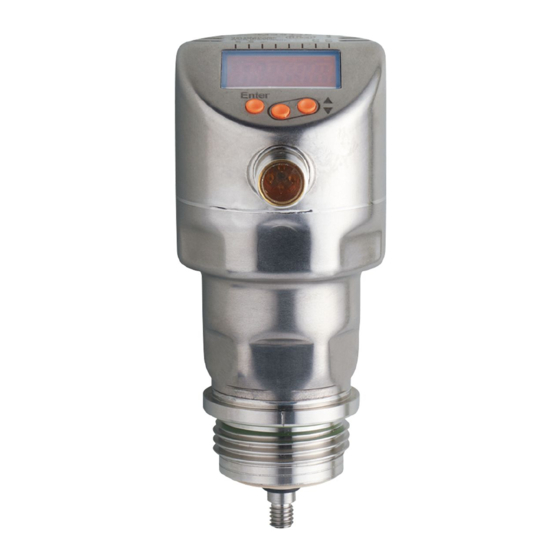
IFM Electronic LR2759 Operating Instructions Manual (47 pages)
Electronic level sensor
Brand:
IFM Electronic
| Category:
Accessories
| Size: 1.16 MB
Table of Contents
Table of Contents
2
1 Preliminary Note
5
Symbols Used
5
2 Safety Instructions
5
3 Items Supplied
6
4 Getting Started
6
5 Functions and Features
6
Applications
7
Restriction of the Application Area
7
6 Function
8
Measuring Principle
8
Outputs
8
Other Features of the Unit
9
Display Functions
9
Analogue Function
9
Switching Functions
11
Damping Function
12
Probes for Different Tank Heights
12
Defined State in Case of a Fault
12
IO-Link
13
Simulation Functions
13
7 Installation
13
Installation Location / Environment
13
Minimum Distances and Connection Piece Diameter
13
Installation in Pipes
14
Applications with Viscous and Fast Flowing Media
15
Fill Openings
15
Heavy Soiling
16
Heavy Foam Build-Up and Turbulence
16
Notes on Tank Adjustment
17
Probe Installation
18
Attaching the Probe
18
Probe Length
19
Shorten the Probe
19
Determine Probe Length
20
Installation of the Unit in the Tank
20
Installation in Open Metal Tanks
21
Installation in Plastic Tanks
22
Note on the Use According to EHEDG
23
Notes on the Use According to 3-A
23
8 Electrical Connection
24
9 Operating and Display Elements
25
10 Menu
26
Menu Structure
26
Explanation of the Menu
28
Main Menu
28
Level EF (Extended Functions)
28
Level CFG (Configuration)
29
EN Level (Environment)
29
Level SIM (Simulation)
29
11 Parameter Setting
30
Parameter Setting in General
30
Basic Settings (Set-Up)
32
Enter Probe Length
32
Carry out Tank Adjustment
32
Configure Display (Optional)
33
Set Output Signals
33
Set Output Function for out 1
33
Set Switching Limits (Hysteresis Function)
33
Set Switching Limits (Window Function)
34
Set Switch-On Delay for Switching Outputs
34
Set Switch-Off Delay for Switching Outputs
34
Set Output Function for OUT2
34
Scale Analogue Signal
35
Set Output Logic for Switching Outputs
35
Set Response of the Outputs in Case of a Fault
35
Set Damping for the Measured Signal
35
Set Delay Time in Case of a Fault
35
Reset All Parameters to Factory Setting
35
Change Basic Settings
36
Re-Enter Probe Length
36
Set to Another Medium
36
Simulation
36
Set Simulation Value
36
Set Simulation Duration
37
Switch Simulation on / off
37
12 Operation
37
Operation with Single Probe
37
Operation with a Bypass or Still Pipe
38
Function Check
38
Operation Indication
38
Read the Set Parameters
39
Change between Length Display and Percentage
39
Error Indications
39
Output Response in Different Operating States
40
13 Technical Data
41
14 Maintenance / Transport
42
Cleaning and Maintenance When Used in 3-A Applications
42
Transport
43
15 Factory Setting
44
16 Notes on Parameter Setting Via IO-Link
44
Application Example
45
Unit Locking / Data Storage (as from IO-Link V1.1)
46
Advertisement
Advertisement
Related Products
IFM Electronic LR2059
IFM Electronic LR2750
IFM Electronic LR3000
IFM Electronic LR3300
IFM Electronic LR7300
IFM Electronic LR8009
IFM Electronic LR8300
IFM Electronic LK7022
IFM Electronic LK7024
IFM Electronic LK8122
IFM Electronic Categories
Accessories
Measuring Instruments
Controller
Control Unit
Security Sensors
More IFM Electronic Manuals
Login
Sign In
OR
Sign in with Facebook
Sign in with Google
Upload manual
Upload from disk
Upload from URL