Table of Contents
Advertisement
Installation and Operation Manual
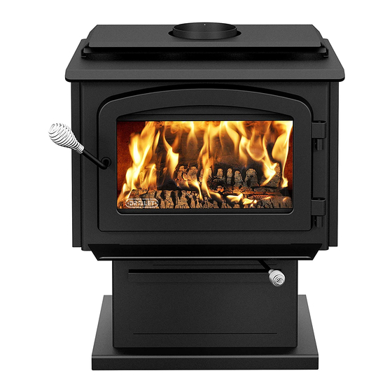
ESCAPE 1500
(DB03135 model)
US Environmental Protection Agency
phase II certified wood stove compliant
with 2020 cord wood standard
Safety tested according to ULC S627,
UL 1482 and UL 737 standards by an
accredited laboratory.
MOBILE
HOME
CONTACT LOCAL BUILDING OR FIRE OFFICIALS ABOUT RESTRICTIONS AND INSTALLATION INSPECTION REQUIREMENTS IN
LOCAL AREA.
READ THIS ENTIRE MANUAL BEFORE INSTALLATION AND USE OF THIS WOOD STOVE. FAILURE TO FOLLOW THESE
INSTRUCTIONS COULD RESULT IN PROPERTY DAMAGE, BODILY INJURY OR EVEN DEATH.
READ AND KEEP THIS MANUAL FOR REFERENCE
Printed in Canada
45996A
Advertisement
Table of Contents

Related Manuals for Drolet Escape 1500


Summary of Contents for Drolet Escape 1500
- Page 1 Installation and Operation Manual ESCAPE 1500 (DB03135 model) US Environmental Protection Agency phase II certified wood stove compliant with 2020 cord wood standard Safety tested according to ULC S627, UL 1482 and UL 737 standards by an accredited laboratory. MOBILE...
- Page 3 It is also highly recommended to register the warranty online at https://www.drolet.ca/en/warranty/warranty-registration/ Registering the warranty will help to quickly find the information needed on the unit. Installation and Operation Manual - Escape 1500 Page 3...
-
Page 4: Table Of Contents
6.5 Exhaust System ........................24 PART B - INSTALLATION ......................26 7. Safety Information and Standards ..................26 7.1 Mobile Home ........................26 7.2 Regulations Covering Stove Installation ................26 7.3 Location of the Certification Label ..................27 Page 4 Installation and Operation Manual - Escape 1500... - Page 5 Appendix 7: Air Tubes and Baffle Installation ................48 Appendix 8: Mobile Home Installation ..................50 Appendix 9: Exploded Diagram and Parts List ................ 51 DROLET Limited Lifetime Warranty ................... 54 Dealer: Installer: Phone Number: Serial Number: Installation and Operation Manual - Escape 1500 Page 5...
- Page 6 CERTIFICATION PLATE Page 6 Installation and Operation Manual - Escape 1500...
-
Page 7: Part A - Operation And Maintenance
This product can expose you to chemicals including carbon monoxide, which is known to the State of California to cause cancer, birth defects or other reproductive harm. For more information go to www.P65warnings.ca.gov/ Installation and Operation Manual - Escape 1500 Page 7... -
Page 8: General Information
This appliance is officially tested and certified by an independent agency. Tested and certified in compliance with CFR 40 part 60, subpart AAA, section 60.534(a)(1(ii) and draft ASTM WK47329-14 Carbon monoxide. Page 8 Installation and Operation Manual - Escape 1500... -
Page 9: Specifications
CAN/CSA- Z240 MH standard. Tested and certified in compliance with CFR 40 part 60, subpart AAA, section 60.534(a)(1(ii) and draft ASTM WK47329-14. Installation and Operation Manual - Escape 1500 Page 9... -
Page 10: Dimensions
406mm Figure 3: Side view Figure 4: Combustion chamber - side view 8" 202mm 17 1/4" 19 5/8" 438mm 498mm Figure 5: Combustion chamber - front view Figure 6: Door opening Page 10 Installation and Operation Manual - Escape 1500... -
Page 11: Materials
Although the stove may be able to heat the main living areas of the house to an adequate temperature, it is strongly recommended to also have a conventional oil, gas or electric heating system to provide backup heating. Installation and Operation Manual - Escape 1500 Page 11... -
Page 12: Emissions And Efficiency
Hardwoods are denser than softwoods. Homeowners with access to both hardwood and softwood use both types for different purposes. Page 12 Installation and Operation Manual - Escape 1500... -
Page 13: Log Length
Do not burn compressed logs made of wax impregnated sawdust or logs with any chemical additives. Follow the manufacturer’s instructions and warnings. Installation and Operation Manual - Escape 1500 Page 13... -
Page 14: Drying Time
− Dry wood is much lighter in weight than wet wood, − The face of a fresh cut feels warm and dry; − The moisture content read by a moisture meter is between 15% to 20%. Page 14 Installation and Operation Manual - Escape 1500... -
Page 15: Operating The Stove
Ensure the blower power cord is not in contact with any surface of the stove to prevent electrical shock or fire damage. Do not run the power cord underneath the Figure 7: Airflow with a blower stove. Installation and Operation Manual - Escape 1500 Page 15... -
Page 16: Burning Wood Efficiently
The conventional method to build a wood fire is to crumple 5 to 10 sheets of newspaper and place them into the firebox and hold them in place with ten pieces of kindling wood. The kindling should be placed on and behind the newspaper. Page 16 Installation and Operation Manual - Escape 1500... -
Page 17: Combustion Cycles
Installation and Operation Manual - Escape 1500 Page 17... -
Page 18: Rekindling A Fire
The best time to remove ash is in the morning, after an overnight fire when the heater is relatively cold, but there is still a little chimney draft to draw the ash dust into the heater and prevent going out into the room. Page 18 Installation and Operation Manual - Escape 1500... -
Page 19: Air Intake Control
This kind of fire is good for mild weather and should provide enough heat for up to four hours. Small fires like this are a good time to use softer wood species and avoid overheating the house. Installation and Operation Manual - Escape 1500 Page 19... - Page 20 5.7.5 Logs Orientation In a relatively square firebox, the wood can be loaded north-south (ends of the logs visible) or east-west (sides of the logs visible). Page 20 Installation and Operation Manual - Escape 1500...
-
Page 21: Maintenance
This is normal and can be easily removed when the heater is cold by wiping with a damp cloth or paper towel and then drying. Installation and Operation Manual - Escape 1500 Page 21... - Page 22 Reinstall the glass, being careful to centre the glass in the door and not to over-tightening the retaining screw. The two main causes of broken door glass are uneven placement in the door and over- tightening the retaining screws. Page 22 Installation and Operation Manual - Escape 1500...
-
Page 23: Door
Remove the split pin by pulling and turning it using pliers. Turn the handle one counterclockwise turn to increase pressure. Reinstall the split pin with a small hammer. Figure 9: Removing the retaining pin Figure 10: Reinstalling the retaining pin Installation and Operation Manual - Escape 1500 Page 23... -
Page 24: Exhaust System
Establish a routine for the fuel, wood burner and firing technique. Check daily for creosote build-up until experience shows how often you need to clean to be safe. Page 24 Installation and Operation Manual - Escape 1500... - Page 25 Do not use the appliance again until the stove and its chimney have been inspected by a qualified chimney sweep or a fire department inspector. Installation and Operation Manual - Escape 1500 Page 25...
-
Page 26: Part B - Installation
This stove must be connected to a chimney complying with the requirements for Type HT chimneys in the Standard for Factory-Built Chimneys for Residential Type and Building Heating Appliances, UL 103 and ULC S629 or to a code-approved masonry chimney with a flue liner. Page 26 Installation and Operation Manual - Escape 1500... -
Page 27: Location Of The Certification Label
For a safe way to reduce clearances refer to section «8.3 Reducing Clearances Safely» Installation and Operation Manual - Escape 1500 Page 27... - Page 28 48" 36" 122 cm 92 cm Figure 11: Clearances - Top Figure 12: Clearances - Corner 84" (L) 213 cm Figure 13: Clearances - Side Page 28 Installation and Operation Manual - Escape 1500...
-
Page 29: Clearances
6" (153 mm) from combustible materials must be used. Only in this case, the same clearances as a certified double wall pipe connector can be used. Installation and Operation Manual - Escape 1500 Page 29... - Page 30 6" (153 mm) from combustible materials must be used. Only in this case, the same clearances as a certified double wall pipe connector can be used. Page 30 Installation and Operation Manual - Escape 1500...
- Page 31 11 ¾" (298 mm) 11 ¾" (298 mm) The pipe distances listed in this table refer to the distances obtained when the stove is installed in accordance with the appliance clearances above mentioned. Installation and Operation Manual - Escape 1500 Page 31...
-
Page 32: Floor Protection
The floor protection at the back of the stove is limited to the stove’s required clearance if such clearance is smaller than 8 inches (203 mm). Only required under the horizontal section (Ho) of the connector. Must exceed each side of the connector by at least 2 inches (51 mm). See «Figure 13: Clearances - Side» Page 32 Installation and Operation Manual - Escape 1500... - Page 33 Brick, with a minimum of 24 gauge (0.61 mm) sheet metal backing, spaced out at least 1" (25 mm)* by non-combustible spacers 12" (305 mm) * In Canada this space can be ⅞" (21 mm). Installation and Operation Manual - Escape 1500 Page 33...
- Page 34 Mounting hardware must not be located closer than 8" (200 mm) from the vertical centre line of the appliance. G) Edge clearance for ceiling shields to side and back walls: 3" (75 mm). Shield extension beyond each side of the appliance: 18" (450 mm). Page 34 Installation and Operation Manual - Escape 1500...
- Page 35 Figure 16: Heat shield clearances Figure 17: Heat shield clearances Figure 18: Heat shield clearances Installation and Operation Manual - Escape 1500 Page 35...
-
Page 36: The Venting System
Only components intended for the brand and model of chimney should be used. Never fabricate or substitute parts from other chimney brands. The chimney must be a type suitable for solid fuel. Page 36 Installation and Operation Manual - Escape 1500... - Page 37 Do not downsize the flue to less than 6" unless the venting system is straight and exceeds 25 feet in height. When passing through a combustible wall, the use of an insulated listed thimble is required. Installation and Operation Manual - Escape 1500 Page 37...
-
Page 38: Minimum Chimney Height
Called ‘stack effect’, it produces a slightly negative pressure in the lower part of the house (compared to the outside) and a slightly positive pressure zone in the high part of the house. Page 38 Installation and Operation Manual - Escape 1500... -
Page 39: Supply Of Combustion Air
(such as a kitchen range exhaust) causes the pressure in the house to become negative relative to outdoors. Figure 21: Air supply in conventional houses Installation and Operation Manual - Escape 1500 Page 39... -
Page 40: Installing The Chimney Connector
They are also more stable and easier to maintain than assemblies with elbows. Horizontal runs of flue pipe should be avoided where possible because they reduce chimney draft. Figure 22: Best Figure 23: Acceptable Figure 24: Avoid Page 40 Installation and Operation Manual - Escape 1500... - Page 41 • A straight flue pipe assembly offers the least restriction to gas flow and results in a stronger draft. Straight assemblies also need less maintenance because there are no corners to collect creosote. • The chimney connector must be clean and in good condition. Installation and Operation Manual - Escape 1500 Page 41...
-
Page 42: Appendix 1: Optional Fresh Air Intake Kit Installation
(HVAC type, must meet ULC S110 or UL 181 class 0 or class 1) (B), sold separately. Refer to air intake kit installation instructions for more details. Page 42 Installation and Operation Manual - Escape 1500... -
Page 43: Appendix 2: Optional Fire Screen Installation
Lift the fire screen upwards and push the bottom part towards the stove then let the fire screen rest on the bottom of the door opening. Warning: Never leave the stove unattended while in use with the fire screen. Installation and Operation Manual - Escape 1500 Page 43... -
Page 44: Appendix 3: Optional Blower Installation
Ensure that the blower’s power cord is not in contact with any surface of the stove to prevent electrical shock or fire damage. Do not run the power cord beneath the stove. Page 44 Installation and Operation Manual - Escape 1500... -
Page 45: Appendix 4: Optional Thermodisc Installation
Screw the thermodisc (C) with the screws (D) provided on the back of the stove. The electrical cord of the thermodisc should not touch any surface of the stove to avoid electric shock or fire. Do not run the power cord under the stove. Installation and Operation Manual - Escape 1500 Page 45... -
Page 46: Appendix 5: Removing The Decorative Panels
APPENDIx 5: REMOVING THE DECORATIVE PANELS To remove the decorative panels (A), remove the screws (B) and push forward on the panel to unhook it from the support (C). Page 46 Installation and Operation Manual - Escape 1500... -
Page 47: Appendix 6: Removing The Airmate
Put the baffle in place. Repeat steps 1 and 2 for the three other tubes. To remove the tubes use the above steps in reverse order. Installation and Operation Manual - Escape 1500 Page 47... - Page 48 Note that secondary air tubes (B) can be replaced without removing the baffle board (A) and that all tubes are identical. Page 48 Installation and Operation Manual - Escape 1500...
-
Page 49: Appendix 8: Mobile Home Installation
APPENDIx 7: MOBILE HOME INSTALLATION For a stove on a pedestal, remove the plugs (A) and screw the base on the floor with the proper hardware (B). Installation and Operation Manual - Escape 1500 Page 49... -
Page 50: Appendix 9: Exploded Diagram And Parts List
APPENDIx 8: ExPLODED DIAGRAM AND PARTS LIST Page 50 Installation and Operation Manual - Escape 1500... - Page 51 BLOWER ASSEMBLY WITH VARIABLE SPEED CONTROL (UP TO 100 CFM) 44073 CROSSFLOW BLOWER 115V-60Hz-39W 100 CFM 60013 POWER CORD 96" X 18-3 type SJT (50 pcs per carton) 44080 RHEOSTAT WITHOUT NUT (MODEL KBMS-13BV) Installation and Operation Manual - Escape 1500 Page 51...
- Page 52 Item Description 44087 RHEOSTAT NUT 44085 RHEOSTAT KNOB AC02055 QUICK CONNECT THERMODISC KIT 44028 CERAMIC THERMODISC F110-20F PL05530-02 THERMODISC BOX (COVER) Page 52 Installation and Operation Manual - Escape 1500...
-
Page 53: Drolet Limited Lifetime Warranty
Shall your unit or a component be defective, contact immediately your DROLET dealer. To accelerate processing of your warranty claim, make sure to have on hand the following information when calling: •... - Page 54 NOTES :...
- Page 56 Resale is strictly prohibited. The manufacturer may update St-Augustin-de-Desmaures (Québec) Canada this document from time to time and cannot be responsible G3A 2H3 for problems, injuries, or damages arising out of the use 418-908-8002 of information contained in any document obtained from https://www.drolet.ca/en/ unauthorized sources. tech@sbi-international.com...
Need help?
Do you have a question about the Escape 1500 and is the answer not in the manual?
Questions and answers