Table of Contents
Advertisement
®
ThermoView
TV40 Series
Thermal Imager Camera
Users Manual
PN 5015206, English, Rev. 1.1, Apr 2019
© 2019 Fluke Process Instruments. All rights reserved. Printed in Germany. Specifications subject to change without notice.
All product names are trademarks of their respective companies.
1.800.561.8187
information@itm.com
www.
.com
Advertisement
Table of Contents

Related Manuals for Fluke ThermoView TV40 Series


Summary of Contents for Fluke ThermoView TV40 Series
-
Page 1: Table Of Contents
Thermal Imager Camera Users Manual PN 5015206, English, Rev. 1.1, Apr 2019 © 2019 Fluke Process Instruments. All rights reserved. Printed in Germany. Specifications subject to change without notice. All product names are trademarks of their respective companies. 1.800.561.8187 information@itm.com www. - Page 2 Warranty The manufacturer warrants this instrument to be free from defects in material and workmanship under normal use and service for the period of two years from date of purchase. This warranty extends only to the original purchaser. This warranty shall not apply to fuses, batteries or any product which has been subject to misuse, neglect, accident, or abnormal conditions of operation.
-
Page 3: Table Of Contents
Table of Contents Chapter Page ..............................3 ABLE OF ONTENTS ............................... 6 IST OF ABLES ..............................7 IST OF IGURES ............................9 OMPLIANCE TATEMENT ............................. 10 AFETY NFORMATION ................................13 ONTACTS ............................... 14 ESCRIPTION 1.1 Available Models ......................................15 1.2 System Architecture ......................................16 .............................. -
Page 4: List Of Tables
................................27 PERATION 6.1 GigE Vision Communication ................................... 27 6.2 LED Status Indicator ....................................... 28 6.3 Shutter..........................................29 6.4 Web Server Application ....................................30 6.4.1 Establishing Communication ................................. 30 6.4.2 Camera Info ......................................30 6.4.3 Camera Access ..................................... 30 6.4.4 Network Configuration ................................... 31 6.4.5 Focus Control ...................................... -
Page 5: List Of Figures
7.3.5.2 Installation ......................................65 7.3.6 Swivel Bracket (A-BR-S) ..................................69 7.3.7 Junction Box (A-TV-JB) ..................................70 7.3.8 Protective Windows (A-TV-PW)................................71 ..............................72 AINTENANCE 8.1 Fail-Safe Operation ......................................72 8.2 Troubleshooting....................................... 72 8.3 Cleaning the Lens ......................................73 ................................74 PPENDIX 9.1 Field of View Calculator .................................... - Page 6 List of Tables Table Page Table 7-1: Available Ethernet PoE Cables ......................39 Table 7-2: Available Power Supply Cables ......................40 Table 8-3: Troubleshooting ........................... 72 Table 9-4: Minimum device temperatures [°C/°F] ....................75 1.800.561.8187 information@itm.com www. .com...
- Page 7 List of Figures Figure Page Figure 1-1: Front and Rear View of ThermoView Series infrared cameras ............14 Figure 1-2: Available Models ..........................15 Figure 1-3: System Architecture for Multiple Cameras and I/O Modules .............. 16 Figure 2-1: Dimensions of ThermoView TV40 ..................... 20 Figure 5-1: Field of View for the Camera ......................
-
Page 8: Compliance Statement
Compliance Statement The device complies with the requirements of the European Directives: EC – Directive 2014/30/EU – EMC EC – Directive 2011/65/EU – RoHS II EN 61326-1: 2013 Electrical measurement, control and laboratory devices - Electromagnetic susceptibility (EMC) EN 50581: 2012 Technical documentation for the evaluation of electrical products with respect to restriction of hazardous substances (RoHS) Electromagnetic Compatibility Applies to use in Korea only. -
Page 9: Safety Information
Safety Information This document contains important information, which should be kept at all times with the instrument during its operational life. Other users of this instrument should be given these instructions with the instrument. Eventual updates to this information must be added to the original document. The instrument can only be operated by trained personnel in accordance with these instructions and local safety regulations. - Page 10 Safety Symbol Description Read all safety information before in the handbook Hazardous voltage. Risk of electrical shock. Warning. Risk of danger. Important information. See manual. Earth (ground) terminal Protective conductor terminal Switch or relay contact DC power supply Conforms to European Union directive. Disposal of old instruments should be handled according to professional and environmental regulations as electronic waste.
-
Page 11: Contacts
To prevent possible electrical shock, fire, or personal injury follow these guidelines: • Read all safety information before you use the product. • Use the product only as specified, or the protection supplied by the product can be compromised. • Do not use the product around explosive gases, vapor, or in damp or wet environments. •... -
Page 12: Description
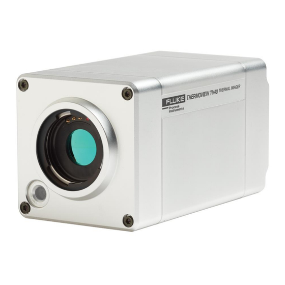
® ThermoView TV40 Series Users Manual, Rev. 1.1, Apr 2019 1 Description The ThermoView Series infrared cameras are rugged thermal imagers designed for industrial process control applications in demanding industrial environments. An IP67 rating for the housing is provided if the camera operates with the standard lens and has no external add-on lens attached. -
Page 13: Available Models
Description Available Models 1.1 Available Models The following ThermoView TV40 model variants are available. Figure 1-2: Available Models Model Temp Range Infrared Resolution Lens Type Field of View Focus Horizontal x Vertical Standard Lens 34° x 25.5° Software controlled 0.75 x Wide 45°... -
Page 14: System Architecture
® ThermoView TV40 Series Users Manual, Rev. 1.1, Apr 2019 1.2 System Architecture Figure 1-3: System Architecture for Multiple Cameras and I/O Modules Windows Computer with ThermoView Software Ethernet Communication (optional Fiber Optic) PoE Ethernet Switch Digital I/O Analog I/O TV43 Camera TV46 Camera 1.800.561.8187... -
Page 15: Technical Data
Technical Data Measurement Specification 2 Technical Data 2.1 Measurement Specification Temperature Range -10°C to 1200°C (14°F to 2192°F) Spectral Response 8 to 14 µm Detector, infrared uncooled focal plane array (micro bolometer) Resolution TV43, infrared 320 x 240 pixels (76,800 pixels), 12 µm pitch TV46, infrared 640 x 480 pixels (307,200 pixels), 12 µm pitch TV43/TV46, visible... -
Page 16: Optical Specifications
® ThermoView TV40 Series Users Manual, Rev. 1.1, Apr 2019 2.2 Optical Specifications The following optical specification is based on the theoretical calculated spot size derived on the pitch of the camera detector array and the lens focal length. Typically, for accurate temperature measurements, the target area needs to be larger than that determined by the calculated theoretical spot sizes, which corresponds to 3 x 3 pixels. -
Page 17: Electrical Specifications
Technical Data Electrical Specifications 2.3 Electrical Specifications Digital Interface GigE Vision (full duplex, 1000 Mbit, TCP/IP, UDP, http-server) 12 – 26 VDC, ± 5% Power Supply Power over Ethernet (IEEE 802.3at), max 25.4 W Power Consumption 16 W (max) lights green at power supply ON 2.4 PC Specifications 1x TV46 camera Processor: x64 architecture... -
Page 18: Dimensions
® ThermoView TV40 Series Users Manual, Rev. 1.1, Apr 2019 2.6 Dimensions Figure 2-1: Dimensions of ThermoView TV40 2.7 Scope of Delivery The scope of standard delivery includes the following: • ThermoView camera • User Manual and Quickstart stored in the camera memory •... -
Page 19: Basics
Basics Measurement of Infrared Temperature 3 Basics 3.1 Measurement of Infrared Temperature All surfaces emit infrared radiation. The intensity of this infrared radiation changes according to the temperature of the object. Depending on the material and surface properties, the emitted radiation lies in a wavelength spectrum of approximately 1 to 20 µm. -
Page 20: Environment
® ThermoView TV40 Series Users Manual, Rev. 1.1, Apr 2019 4 Environment 4.1 Ambient Temperature Without water cooling, the ThermoView camera is designed for ambient operating temperatures between -15 to 50°C (5 to 122°F). With water cooling equipment, it can be used in environments at higher temperatures. By forcing water circulation, it is possible to maintain cooled internal housing temperatures. -
Page 21: Installation
Installation Positioning 5 Installation Risk of Personal Injury When this instrument is being used in a critical process that could cause property damage and personal injury, the user should provide a redundant device or system that will initiate a safe process shutdown in the event that this instrument should fail. -
Page 22: Network
® ThermoView TV40 Series Users Manual, Rev. 1.1, Apr 2019 mounting to provide the required alignment accuracy. Avoiding or removing physical mounting limitations and obstructions in the camera’s optical path, may also be required. 5.5 Network The number of cameras in a network is only limited by the PC performance (required frames per second fps). This means the need to consider the speed capability of the network card for transmitting the data and the performance of the CPU for processing and displaying all data. -
Page 23: Figure 5-3: Connecting The Ethernet M12 Cable To The Camera
Installation Cabling Figure 5-3: Connecting the Ethernet M12 Cable to the Camera Figure 5-4: Exemplary Ethernet M12 Cable Ethernet cables offered by the manufacturer can be found as electrical accessories, see section 7.2.1 Ethernet PoE Cable (A-CB-xx-M12-W08-xx), page 39. 1.800.561.8187 information@itm.com www. -
Page 24: Power Supply Cable
® ThermoView TV40 Series Users Manual, Rev. 1.1, Apr 2019 5.6.2 Power Supply Cable To connect the power supply cable, follow the steps below: • Connect the power connector to the camera • Tighten the outer nut of the female connector •... -
Page 25: Operation
Operation GigE Vision Communication 6 Operation 6.1 GigE Vision Communication The GigE Vision communication is based upon the very fast Gigabit Ethernet (GigE) link, which allows data rates of up to 125 MB/s over cable runs up to 100 m (328 ft.). For digital cameras, especially in the professional image processing domain, is GigE the first-class interface. -
Page 26: Led Status Indicator
® ThermoView TV40 Series Users Manual, Rev. 1.1, Apr 2019 6.2 LED Status Indicator The ThermoView camera has a built-in multi-color LED in the rear panel, which indicates the current health and alarm status. Figure 6-1: LED Status Indicator Status Indicator The LED patterns are: Blinking yellow –... -
Page 27: Shutter
Operation Shutter 6.3 Shutter The camera is equipped with an internal lens shutter. The shutter closes automatically required for a reference recalibration to improve camera performance. It is not a substitute for a factory blackbody calibration. With the shutter closed, no temperature measurements are taking place. 1.800.561.8187 information@itm.com www. -
Page 28: Web Server Application
® ThermoView TV40 Series Users Manual, Rev. 1.1, Apr 2019 6.4 Web Server Application The ThermoView camera is equipped with an onboard web-server. Several information is available and will be displayed using a standard web browser. Furthermore, several settings can be initiated and transferred to the imager. -
Page 29: Network Configuration
Operation Web Server Application Figure 6-3: Dialog Box for Uploading new Firmware <Download from Camera> – opens a file explorer which allows you to download important camera related files such as the installation file for the ThermoView Software and for the ThermoView Software light as well as the firmware file. -
Page 30: Focus Control
® ThermoView TV40 Series Users Manual, Rev. 1.1, Apr 2019 6.4.5 Focus Control The camera is equipped with a motorized focus. The focus setting is applied to the infrared image only. Use the handwheel control to get a sharp image. Clicking on the + and – buttons allows a precise finetuning of the focus control. -
Page 31: Accessories
Accessories Add-on Lenses 7 Accessories A full range of accessories for various applications and industrial environments are available. Accessories include items, that may be ordered at any time and added on-site. 7.1 Add-on Lenses All available add-on lenses are not water tight and have a degraded IP54 rating. There is no need to change the transmission factor in the camera with an added add-on lens. -
Page 32: Wide Lens 0.75X
® ThermoView TV40 Series Users Manual, Rev. 1.1, Apr 2019 7.1.1 Wide Lens 0.75x Field of View (FOV) 45° x 34° (horizontal x vertical) Instantaneous Field of View (IFOV) 2.5 mrad (1 pixel) Measurement Field of View (MFOV) 7.4 mrad (3 x 3 pixel) 152 mm to ∞... -
Page 33: Tele Lens 2X
Accessories Add-on Lenses 7.1.1 Tele Lens 2x Field of View (FOV) 17° x 12.7° (horizontal x vertical) Instantaneous Field of View (IFOV) 0.9 mrad (1 pixel) Measurement Field of View (MFOV) 2.8 mrad (3 x 3 pixel) 406 mm to ∞ (1.3 ft to ∞) Focus Range (infrared) Focus, fixed (visible) 600 mm (1.96 ft) -
Page 34: Tele Lens 4X
® ThermoView TV40 Series Users Manual, Rev. 1.1, Apr 2019 7.1.2 Tele Lens 4x Field of View (FOV) 8.5° x 6.3° (horizontal x vertical) Instantaneous Field of View (IFOV) 0.5 mrad (1 pixel) Measurement Field of View (MFOV) 1.4 mrad (3 x 3 pixel) 2540 mm to ∞... -
Page 35: Macro Tv43
Accessories Add-on Lenses 7.1.3 Macro TV43 Field of View (FOV) 16.7° x 12.5° (horizontal x vertical) 10.8 mm to ∞ (0.42 in to ∞) Focus, fixed (infrared) Table 7-5: Spot Sizes for Macro TV43 Minimum detectable spot size Minimum measurement area Measuring distance Thermal image (H x V) (1 pixel) -
Page 36: Electrical Accessories
® ThermoView TV40 Series Users Manual, Rev. 1.1, Apr 2019 7.2 Electrical Accessories The following electrical accessories are available: • Ethernet PoE Cable (A-CB-xx-M12-W08-xx) • Power Supply Cable (A-CB-xx-PS-xx) • Ethernet Cable (A-CB-LT-RJ45-25) • Ethernet Cable Short (A-CB-LT-RJ45-03) • Fiber Optic Cable (A-CB-FO-xxx) •... -
Page 37: Ethernet Poe Cable (A-Cb-Xx-M12-W08-Xx)
Accessories Electrical Accessories 7.2.1 Ethernet PoE Cable (A-CB-xx-M12-W08-xx) The Ethernet PoE cable comes with an eight-pin male M12 connector, assigned to the cameras rear eight-socket female M12 connector. The corresponding end of the Ethernet PoE cable is equipped with a general RJ45 snap- in connector. -
Page 38: Power Supply Cable (A-Cb-Xx-Ps-Xx)
® ThermoView TV40 Series Users Manual, Rev. 1.1, Apr 2019 7.2.2 Power Supply Cable (A-CB-xx-PS-xx) The power supply cable comes with a three-socket female M16 connector, assigned to the cameras rear three pin male M16 connector. The corresponding end of the power supply cable is carried out as a pig tail, to connect to an external power supply device. -
Page 39: Ethernet Cable (A-Cb-Lt-Rj45-25)
Accessories Electrical Accessories 7.2.3 Ethernet Cable (A-CB-LT-RJ45-25) The Ethernet cable comes with RJ45 connectors on both ends in a length of 25 m (82 ft). Figure 7-6: Ethernet Cable 7.2.4 Ethernet Cable Short (A-CB-LT-RJ45-03) The Ethernet cable short comes with RJ45 connectors on both ends in a length of 0.3 m (1 ft). Figure 7-7: Ethernet Cable Short 1.800.561.8187 information@itm.com... -
Page 40: Fiber Optic Cable (A-Cb-Fo-Xxx)
® ThermoView TV40 Series Users Manual, Rev. 1.1, Apr 2019 7.2.5 Fiber Optic Cable (A-CB-FO-xxx) Use fiber optic communication for Ethernet cable runs beyond 90 m (295 ft). The cables are available in the following lengths: • 150 m (492 ft), part number A-CB-FO-150 •... -
Page 41: Poe Injector (A-Tv-Poe1)
Accessories Electrical Accessories 7.2.6 PoE Injector (A-TV-POE1) The PoE Injector (A-TV-POE1) is intended to use in office environments. With PoE (Power over Ethernet), the injector transfers both data and electrical power to Ethernet-enabled devices using a standard CAT5 cable. The injector injects up to 30 W for the attached device(s). It operates at an ambient temperature up to 55ºC (131°F). -
Page 42: Poe Injector Industrial (A-Tv-Poe2)
® ThermoView TV40 Series Users Manual, Rev. 1.1, Apr 2019 7.2.7 PoE Injector Industrial (A-TV-POE2) The PoE Injector Industrial (A-TV-POE2) is intended to use in industrial environments. With PoE (Power over Ethernet), the injector transfers both data and electrical power to Ethernet-enabled devices using a standard CAT5 cable. - Page 43 Accessories Electrical Accessories Communications Standard IEEE 802.3, 802.3u, 802.3x, 802.3af/at, 802.3ab 10/100/1000Base-T (X) Transmission Distance max. 100 m (328 ft) Transmission Speed up to 1000 Mbps Interface Connectors PoE OUT: RJ45, DATA IN: RJ45 6-pin removable screw terminal Power Power Consumption max.
-
Page 44: Power Supply Din Rail (A-Ps-Din-24V)
® ThermoView TV40 Series Users Manual, Rev. 1.1, Apr 2019 7.2.8 Power Supply DIN Rail (A-PS-DIN-24V) The DIN-rail mount industrial power supply delivers isolated dc power and provides short circuit and overload protection. Risk of Personal Injury To prevent electrical shocks, the power supply must be used in protected environments (cabinets)! Technical data: Protection class... -
Page 45: Fiber Optic To Ethernet Converter (A-Con-Fo-Rj45)
Accessories Electrical Accessories 7.2.9 Fiber Optic to Ethernet Converter (A-CON-FO-RJ45) The Fiber Optic Converter (A-CON-FO-RJ45) is an industrial Ethernet switch with 6 RJ45 GBit Ethernet ports and 2 multi-mode GBit fiber optic ports. The converter is DIN-rail or wall mountable. Figure 7-12: Fiber Optic to Ethernet Converter Figure 7-13: Dimensions measures in mm [in]... - Page 46 ® ThermoView TV40 Series Users Manual, Rev. 1.1, Apr 2019 Communications Standard IEEE 802.3, 802.3u, 802.3ab, 802.3x, IEEE 802.3z 10/100/1000Base-T (X), 1000Base-SX or 1000Base-LX Transmission Distance Ethernet: max. 100 m (328 ft) Multi-mode: up to 550 m (1804 ft) Transmission Speed up to 1000 Mbps Optical Fiber Multi-mode...
-
Page 47: Ethernet Switch (A-Con-Sw)
Accessories Electrical Accessories 7.2.10 Ethernet Switch (A-CON-SW) The Ethernet Switch (A-CON-SW) has 4 x 10/100/1000BASE-T Ethernet ports with PoE+ functionality and 2 x SFP sockets. It works within a wide operating temperature range. This switch can provide 30 W output per PoE port. - Page 48 ® ThermoView TV40 Series Users Manual, Rev. 1.1, Apr 2019 Communications Standard IEEE 802.3, 802.3u, 802.3x, 802.3af/at, 802.3ab, 802.3z 10/100/1000BASE-T 1000BASE-SX/LX/LHX/XD/ZX/EZX Transmission Distance Ethernet: max. 100 m (328 ft) SFP: up to 110 km (depends on SFP) Transmission Speed Copper: 10/100/1000 Mbps, Auto-Negotiation Gigabit Fiber: Up to 1000 Mbps Interface Connectors...
-
Page 49: I/O Modules
Accessories Electrical Accessories 7.2.11 I/O Modules The following I/O modules are available for the TV40 imager: • A-CON-BASICKIT Basic Kit, consists of the following items: Fieldbus Coupler 750-352 Supply Module 750-602 End Module 750-600 Support software with communication cable • A-CON-16DI Digital Input Module 750-1406 •... -
Page 50: Mechanical Accessories
® ThermoView TV40 Series Users Manual, Rev. 1.1, Apr 2019 7.3 Mechanical Accessories The following mechanical accessories are available: • Mounting Base (A-TV-MB) • Air Purge Collar (A-TV-AP) • Water Cooling Enclosure (A-TV-AP-WC) • Protective Enclosure (A-TV-WC) • Outdoor Enclosure (A-TV-ENC) •... -
Page 51: Mounting Base (A-Tv-Mb)
Accessories Mechanical Accessories 7.3.1 Mounting Base (A-TV-MB) The Mounting Base (A-TV-MB) is to adapt the imager in an easy way to any kind of fixture. For the fixture to tripods or swivel brackets, the mounting base provides 2 inner ¼” – 20 holes. Figure 7-16: Mounting Base 1.800.561.8187 information@itm.com... -
Page 52: Air Purge Collar (A-Tv-Ap)
® ThermoView TV40 Series Users Manual, Rev. 1.1, Apr 2019 7.3.2 Air Purge Collar (A-TV-AP) The Air Purge Collar (A-TV-AP) is used to keep dust, moisture, airborne particles, and vapors away from the lens. Air flows into the 1/8” NPT fitting and out the front aperture. Clean filtered (or “instrument”) air is recommended to avoid contaminants from settling on the lens. - Page 53 Accessories Mechanical Accessories To install the Air Purge Collar, follow the mounting steps as described below. Use the enclosed screws to attach the mounting carriage to the bottom of the camera body. Place the camera body on the base plate of the air purge.
-
Page 54: Water Cooling Enclosure (A-Tv-Ap-Wc)
® ThermoView TV40 Series Users Manual, Rev. 1.1, Apr 2019 7.3.3 Water Cooling Enclosure (A-TV-AP-WC) The Water Cooling Enclosure (A-TV-AP-WC) allows the camera to be used in ambient temperatures up to 140°C (284°F) with water cooling. The cooling media should be connected using 1/8” NPT fittings requiring 6 mm (0.24 in) inner diameter and 8 mm (0.31 in) outer diameter for the tube. - Page 55 Accessories Mechanical Accessories 1.800.561.8187 information@itm.com www. .com...
-
Page 56: Protective Enclosure (A-Tv-Wc)
® ThermoView TV40 Series Users Manual, Rev. 1.1, Apr 2019 7.3.4 Protective Enclosure (A-TV-WC) When the camera is installed in dirty and hot environments, the protective enclosure (A-TV-WC) provides water cooling and air purge for protection. 7.3.4.1 Air Barrier The flange for window cleaning uses ventilation to create an air barrier on the front of the housing to prevent any deposits of dust on the outer surface of the window. -
Page 57: Specification
Accessories Mechanical Accessories 7.3.4.2 Specification Scope of delivery • Enclosure with cooling jacket and Zinc Selenide window • 2x cable glands (M25 x 1.5) • Mounting material Environment Rating IP67 Ambient temperature 200°C (392°F) with a flow rate of 6 l / min (1.6 gal / min), water at 20°C (68°F) inlet temperature and 6 bar (87 psi) for front air barrier Air pressure 4 to 6 bar (58 to 87 psi) recommended... -
Page 58: Installation
® ThermoView TV40 Series Users Manual, Rev. 1.1, Apr 2019 7.3.4.3 Installation Note The camera can only be mounted in the protective housing with standard lens or with wide lens. A mounting with tele or macro lens is not possible! Note For better handling, an additional handle can optionally be mounted on the housing. - Page 59 Accessories Mechanical Accessories Secure the camera with tooth lock washer and pan head screw to the rail. Use the delivered hex wrench. Note a distance between the camera front and the rail of approx. 10 mm (0.39 in) approx. 10 mm (0.39 in) Fit the two cable glands to the rear lid.
- Page 60 ® ThermoView TV40 Series Users Manual, Rev. 1.1, Apr 2019 Fix the earth cable onto the rail. Pass all cables through the enclosure cable glands. Do not tight the end caps for the moment. Plug the connectors to the camera. Connect the protective inductor on the inner side of the rear lid.
- Page 61 Accessories Mechanical Accessories Remount the rear lid onto the enclosure. Fix two six hexagon socket screws each with a tooth lock washer as shown. Fix the remaining four hexagon socket screws (without tooth lock washers) at the remaining positions. Tight the end caps. wrench size W30 (30 mm/1.2 in) torque about 10 Nm) 1.800.561.8187...
-
Page 62: Outdoor Enclosure (A-Tv-Enc)
® ThermoView TV40 Series Users Manual, Rev. 1.1, Apr 2019 7.3.5 Outdoor Enclosure (A-TV-ENC) In case, the thermal imager must be mounted in outdoor environments, an outdoor enclosure (A-TV-ENC) ensures weatherproofed installations. It provides a high protection rate, a sunshield, and a temperature-controlled heater for cooler environments. -
Page 63: Installation
Accessories Mechanical Accessories Figure 7-22: Dimensions 7.3.5.2 Installation Note The camera can only be mounted in the outdoor enclosure with standard lens or with wide lens. A mounting with tele or macro lens is not possible! Note To avoid erroneous readings, ensure that the transmission of 0.87 for the built-in protective window (Germanium) must be set in the thermal imager! Note For installation / commissioning of the internal heating element be referred to the enclosed instructions of... - Page 64 ® ThermoView TV40 Series Users Manual, Rev. 1.1, Apr 2019 When delivered, the housing cover is not yet in its final position. Push the housing cover upwards until the key on the housing cover snaps into the slot of the housing body.
- Page 65 Accessories Mechanical Accessories Mount the sealing inner and the end cap to each cable. Pass all cables through the enclosure cable glands. Plug the connectors to the camera. Tight the end caps. Installation with PoE requires only one cable. Close the unused cable gland with the enclosed sealing body.
- Page 66 ® ThermoView TV40 Series Users Manual, Rev. 1.1, Apr 2019 Remount the rear lid onto the enclosure. 1.800.561.8187 information@itm.com www. .com...
-
Page 67: Swivel Bracket (A-Br-S)
Accessories Mechanical Accessories 7.3.6 Swivel Bracket (A-BR-S) The Swivel Bracket (A-BR-S) is to mount the camera in a moveable position, to correct in an easy way the pitch and yaw orientation. For a correct imager orientation, you can pitch (0° – 90°) and swivel (0° - 360°) the imager sighting axis. -
Page 68: Junction Box (A-Tv-Jb)
® ThermoView TV40 Series Users Manual, Rev. 1.1, Apr 2019 7.3.7 Junction Box (A-TV-JB) The Junction Box (A-TV-JB) provides the space to the mount the power supplies, I/O modules, Ethernet converters and switches. Figure 7-24: Junction Box Specification: sheet steel, powder-coated Dimensions (W x H x D) 380 x 300 x 210 mm (15 x 11.8 x 8.3 in) Net weight... -
Page 69: Protective Windows (A-Tv-Pw)
Accessories Mechanical Accessories 7.3.8 Protective Windows (A-TV-PW) The Protective Window (A-TV-PW) can be used to protect the camera’s optics against dust and other contamination. The window is attached directly to the camera via the bayonet lock. The protective window is made from Germanium with a transmission factor of 0.94. To avoid erroneous readings, ensure that the transmission for the protective window must be set in the camera via software. -
Page 70: Maintenance
® ThermoView TV40 Series Users Manual, Rev. 1.1, Apr 2019 8 Maintenance Our sales representatives and customer service staff are always at your disposal for questions regarding applications, calibration, repair, and solutions to specific problems. Please contact your local sales representative if you need assistance. -
Page 71: Cleaning The Lens
Maintenance Cleaning the Lens 8.3 Cleaning the Lens Keep the lens at all times. Care should be taken when cleaning the lens. To clean the window, do the following: Lightly blow off loose particles with “canned” air (used for cleaning computer equipment) or a small squeeze bellows (used for cleaning camera lenses). -
Page 72: Appendix
® ThermoView TV40 Series Users Manual, Rev. 1.1, Apr 2019 9 Appendix 9.1 Field of View Calculator It is important that the ThermoView camera is mounted at a distance from the target, sufficient to be able to “see” the entire area of interest. For this reason, the manufacturer provides a field of view calculating software called “Spot Size Calculator”, which allows the calculation of the thermal image size (Field of View FOV) and the pixel size (Instantaneous Field of View IFOV) for a given lens, based on a specific camera mounting distance. -
Page 73: Avoidance Of Condensation
Appendix Avoidance of Condensation 9.2 Avoidance of Condensation If environmental conditions make water cooling necessary, it is strictly recommended to check whether condensation will be a real problem or not. Water-cooling also causes a cooling of the air in the inner part of the sensor, thereby decreasing the capability of the air to hold water. -
Page 74: Determination Of Emissivity
® ThermoView TV40 Series Users Manual, Rev. 1.1, Apr 2019 9.3 Determination of Emissivity Emissivity is a measure of an object’s ability to absorb and emit infrared energy. It can have a value between 0 and 1.0. For example, a mirror has an emissivity of < 0.1, while the so-called blackbody reaches an emissivity value of 1.0. - Page 75 Appendix Typical Emissivity Values Table 9-1: Typical Emissivity Values for Metals 8 – 14 µm Material Aluminum Unoxidized 0.02-0.1 Oxidized 0.2-0.4 Alloy A3003, Oxidized Roughened 0.1-0.3 Polished 0.02-0.1 Brass Polished 0.01-0.05 Burnished Oxidized Chromium 0.02-0.2 Oxidized Copper Polished 0.03 Roughened 0.05-0.1 Oxidized 0.4-0.8...
- Page 76 ® ThermoView TV40 Series Users Manual, Rev. 1.1, Apr 2019 8 – 14 µm Material Monel (Ni-Cu) 0.1-0.14 Oxidized 0.7-0.9 Nickel Oxidized 0.2-0.5 Electrolytic 0.05-0.15 Platinum Black Silver 0.02 Steel Cold-Rolled 0.7-0.9 Ground Sheet 0.4-0.6 Polished Sheet Molten Oxidized 0.7-0.9 Stainless 0.1-0.8 Tin (Unoxidized)
- Page 77 Appendix Typical Emissivity Values Table 9-2: Typical Emissivity Values for Non-Metals 8 – 14 µm Material Asbestos 0.95 Asphalt 0.95 Basalt Carbon Unoxidized 0.8-0.9 Graphite 0.7-0.8 Carborundum Ceramic 0.95 Clay 0.95 Coke 0.95-1.00 Concrete 0.95 Cloth 0.95 Glass Plate 0.85 “Gob”...
Need help?
Do you have a question about the ThermoView TV40 Series and is the answer not in the manual?
Questions and answers