Table of Contents
Advertisement
Quick Links
Advertisement
Table of Contents

Related Manuals for IFM VNB211


Summary of Contents for IFM VNB211
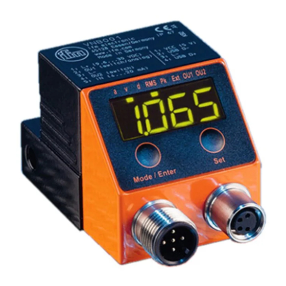
- Page 1 Operating instructions Vibration sensor VNB211...
-
Page 2: Table Of Contents
Content 1 Preliminary note ���������������������������������������������������������������������������������������������������4 1�1 Notes on this document ���������������������������������������������������������������������������������4 1�2 Symbols used ������������������������������������������������������������������������������������������������4 2 Safety instructions �����������������������������������������������������������������������������������������������4 2�1 General ����������������������������������������������������������������������������������������������������������4 2�2 Installation and connection ����������������������������������������������������������������������������4 2�3 Tampering with the device �����������������������������������������������������������������������������5 3 Functions and features ����������������������������������������������������������������������������������������5 4 Installation������������������������������������������������������������������������������������������������������������6 5 Electrical connection ��������������������������������������������������������������������������������������������7 5�1 M8/USB interface ������������������������������������������������������������������������������������������7 5�2 History values ������������������������������������������������������������������������������������������������7... - Page 3 8�1�2 Characteristic vibration value �������������������������������������������������������������14 8�1�3 External process value �����������������������������������������������������������������������14 9 Menu ������������������������������������������������������������������������������������������������������������������14 9�1 Menu structure ���������������������������������������������������������������������������������������������15 9�2 Main menu ���������������������������������������������������������������������������������������������������15 9�2�1 V1 menu ���������������������������������������������������������������������������������������������16 9�2�2 V2 menu ���������������������������������������������������������������������������������������������16 9�2�3 EV1 menu �������������������������������������������������������������������������������������������16 9�2�4 EV2 menu �������������������������������������������������������������������������������������������17 9�2�5 EP1 menu �������������������������������������������������������������������������������������������17 9�2�6 EP2 menu �������������������������������������������������������������������������������������������18 9�2�7 Ext menu ��������������������������������������������������������������������������������������������18 9�2�8 Out menu ��������������������������������������������������������������������������������������������19...
-
Page 4: Preliminary Note
Technical data, approvals, accessories and further information at www�ifm�com� 1.1 Notes on this document This document applies to devices of the type "vibration sensor" (art� no�: VNB211)� It is part of the device and contains information about the correct handling of the product�... -
Page 5: 2�3 Tampering With The Device
3 Functions and features The parameters of the device are mainly set via the VES004 PC software� The device manual can be found at www�ifm�com Monitoring of • 2 sensor-internal characteristic vibration values (a/v, RMS/peak) • 2 external characteristic vibration values (a/v, RMS/peak via VNA001... -
Page 6: Installation
4 Installation Please note the following points when installing the unit: ► Mount only in a thick housing wall (e�g� crane hook thread)� ► Mount vertically to the machine surface using the spacer adapter in the direction of the strongest vibrations�... -
Page 7: Electrical Connection
5 Electrical connection The unit must be connected by a qualified electrician� The national and international regulations for the installation of electrical equipment must be adhered to� Voltage supply to EN 50178, SELV, PELV� Disconnect power before connecting the unit� Pin 1: L+ 9�6���30 V DC Pin 2: Out 1... -
Page 8: 5�3 Real-Time Clock
→ 8.1 Programming via pushbuttons 6.1 Monitoring function The VNB211 can monitor up to two internal characteristic vibration values� The characteristic values are activated and configured via the PC software� Monitoring can be effected in acceleration or vibration velocity in a frequency range that can be set�... -
Page 9: 6�3 Output Function (Switching Output And Analogue Output)
6.3 Output function (switching output and analogue output) The two outputs of the VNB211 are used for the alarm (pre-alarm, main alarm)� The first output (OU1) can be used as digital or analogue output� The switching logic (which characteristic values are alarmed in which way) can be set only in the PC software�... -
Page 10: 6�5�2 Settings
6.5.2 Settings Averaging = 1: averaging deactivated Averaging 0�01; strong averaging 6.5.3 Diagram averaging 4 7 10 13 16 19 22 25 28 31 34 37 40 43 46 49 52 55 58 61 64 67 70 73 76 79 82 85 88 91 94 97 1: Measured value 2: Averaged diagnostic value (averaging = 0�125) 6.6 Measuring function... -
Page 11: Operating And Display Elements
7 Operating and display elements 7.1 LED display Mode/Enter 1...8: LED display 1: LED green a = vibration velocity a [g] or [m/s²] 2: LED green v = vibration velocity v [mm/s] or [in/s] 3: LED green d = not used 4: LED green RMS = average value 5: LED green Pk = peak value 6: LED green Ext = process value of the external transducer... -
Page 12: 7�2 7-Segment Display
7.2 7-segment display • Displays the damage level (green, yellow, red) If the segment display changes the colour, the switch-on and switch-off delays or the hysteresis are not considered� • Display of the current measured value for the selected object •... -
Page 13: 7�4 Operating Mode External Process Value
Colour segment display: red Current measured value external analogue sensor, temperature ϑ = 95 °C Parameters - Pre-alarm ESP1 = 50 °C - Main alarm ESP2 = 90 °C > Outputs OU1 and OU2 are active The LEDs OU1 and OU2 indicate the alarm condition, not the voltage level (high, low) at the output�... -
Page 14: Device Configuration
8 Device configuration 8.1 Programming via pushbuttons The following settings can be made via the pushbuttons on the unit� 8.1.1 Global VNB parameters - Scaling of the input (4���20 mA, for use for the external process value) - Scaling of the output (4���20 mA, if OU1 = analogue) - Switching function of the outputs (NC, NO) - Switch-on and switch-off delays - Self-test... -
Page 15: 9�1 Menu Structure
9.1 Menu structure 9.2 Main menu Vibration Main menu Ext. input... -
Page 16: 9�2�1 V1 Menu
9.2.1 V1 menu 9.2.2 V2 menu 9.2.3 EV1 menu The menu for the external characteristic vibration value 1 is only available if it was configured in the PC software�... -
Page 17: 9�2�4 Ev2 Menu
9.2.4 EV2 menu The menu for the external characteristic vibration value 2 is only available if it was configured in the PC software� 9.2.5 EP1 menu... -
Page 18: 9�2�6 Ep2 Menu
9.2.6 EP2 menu The menu for the external process value 2 is only available if it was configured in the PC software� 9.2.7 Ext menu... -
Page 19: 9�2�8 Out Menu
9.2.8 Out menu... -
Page 20: 9�3 Explanation Of The Menu
9.3 Explanation of the menu Menu level 1 V1 ) Sub-menu for the characteristic vibration value 1 V2 ) Sub-menu for the characteristic vibration value 2 EV1) Sub-menu for the external characteristic vibration value 1 with respective configuration EV2) Sub-menu for the external characteristic vibration value 2 with respective configuration EP1) Sub-menu for the external process value 1... - Page 21 Sub-menu external characteristic vibration values EV1) and EV2) with respective configuration ESP1 Switch point pre-alarm If the switch point is exceeded, - OU1 switches, if it is digital - the yellow LED "OU1" lights - the measured value display changes to yellow ESP2 Switch point main alarm If the switch point is exceeded,...
-
Page 22: Parameter Setting Via The Pushbuttons On The Unit
ASP1 Scaling current output with respective configuration (OU1 = analogue), value at 4 mA AEP1 Scaling current output with respective configuration (OU1 = analogue), value at 20 mA Switching logic OU2 NO, NC (normally open, normally closed) Switch-on delay for OU1 (0���60 s) Switch-off delay for OU1 (0���60 s) Switch-on delay for OU2 (0���60 s) Switch-off delay for OU2 (0���60 s) -
Page 23: 10�1�1 Change From Menu Level 1 To The Sub-Menu
Set parameter value ► Press [Set]. > The current setting value of the Mode/Enter Set parameter is displayed� ► Press [Set] for 3 s. ► Setting of the decimal point (cc� cc) and the sign by pressing [Set] several times� ►... -
Page 24: 10�1�2 Locking / Unlocking
10.1.2 Locking / unlocking The unit can be locked electronically to prevent unintentional settings� ► Make sure that the unit is in the normal operating mode� Mode/Enter Set ► Press [Mode/Enter] + [Set] for 10 s. > [Loc] is displayed. During operation: [Loc] is briefly displayed if you try to change parameter values. -
Page 25: Time Diagrams
13 Time diagrams 13.1 Averaging for a characteristic vibration value The time diagram shows the effect of averaging for a characteristic vibration value� The outputs are configured as normally open (OU1 and OU2 → NO), averaging (AUER) = 0�25� [mm/s] t [s] OU 2 (n.o.) ds2, dr2 = 0 s... -
Page 26: 13�2 Switching Delay For The Upper Limit Monitor
13.2 Switching delay for the upper limit monitor The time diagram shows the effect of the switching delay on the analogue input for an upper limit monitor (ESP1 < ESP2)� The outputs are set as normally closed (OU1 and OU2 → NC). Analogue In [°C] ESP2... - Page 27 If the switching delays of pre-alarm and main alarm are set differently: - main alarm already switched on, pre-alarm not yet switched on - pre-alarm already switched off, main alarm not yet switched off...
-
Page 28: 13�3 Switching Delay For The Lower Limit Monitor
13.3 Switching delay for the lower limit monitor The time diagram shows the effect of the switching delay on the analogue input for a lower limit monitor (ESP1 > ESP2)� The outputs are set as normally closed (OU1 and OU2 → NC). Analogue In [°C] ESP1... -
Page 29: Factory Setting
14 Factory setting Factory setting User setting Global settings Input filter 10 Hz high pass Characteristic vibration value 1 Filter 1000 Hz low pass Evaluation method Degree of integration Vibration velocity Measurement time 0�25 s History interval 300 s History values Maximum value + average value Characteristic vibration... - Page 30 Factory setting User setting History interval 300 s History values Maximum value + average value External process value 2 Not used Measurement time History interval History values External Not used characteristic vibration value 1 Filter Evaluation method Degree of integration Measurement time History interval History values...
- Page 31 Factory setting User setting Switching logic pre-alarm Characteristic vibration value 1 or characteristic vibration value 2 or external process value Switching logic main alarm Characteristic vibration value 1 or characteristic vibration value 2 or external process value The following list indicates the factory settings of the parameters that can be set via the pushbuttons on the unit: Factory setting User setting...
- Page 32 Factory setting User setting ESP1 (pre-alarm) ESP2 (main alarm) AUER (averaging) External process value 1 ESP1 (pre-alarm) ESP2 (main alarm) Eh1 (hysteresis pre-alarm) (Hysteresis main alarm) External process value 2 Not used ESP1 (pre-alarm) ESP2 (main alarm) Eh1 (hysteresis pre-alarm) (Hysteresis main alarm) External input EASP (4 mA)
- Page 33 Factory setting User setting dS2 switch-on delay main 0 [s] alarm dr2 switch-off delay main 0 [s] alarm Display Metric...
Need help?
Do you have a question about the VNB211 and is the answer not in the manual?
Questions and answers