
Subscribe to Our Youtube Channel
Related Manuals for Technogym PLURIMA


Summary of Contents for Technogym PLURIMA
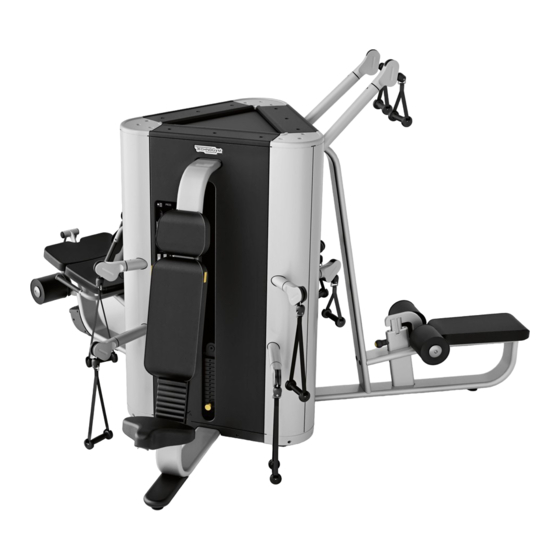
- Page 1 P L U R I M A T H E S M A R T M U L T I S T A T I O N TOWER - Core & Leg Extension/Curl - Press & Overhead Press - High & Low Pull User manual...
-
Page 2: Table Of Contents
Contents Important safety instructions ............... 3 Reaching the inside parts ................42 Personal safety ....................5 Replacing the cable ..................46 Identification of the manufacturer and equipment ........8 Core & Leg Extension/Curl ..............47 Using the equipment ..................9 Press & Overhead Press ................59 Core &... -
Page 3: Important Safety Instructions
To reduce the risk of injury, take the following precautions. The products in the Plurima range are units of fixed weight training equipment units that can be used for body-building or sculpting, physical activity aimed at keeping in shape, physical education and training for specific competitions and sports. - Page 4 Never operate any equipment if it has damaged power supply cord, if it is not working properly or if it has been dropped or damaged. In these circumstances, contact the Technogym Technical Support service. Keep hands away from moving parts.
-
Page 5: Personal Safety
Prior to each use, check the equipment and make sure the cable is positioned correctly in the grooves of all the pulleys and check cable wear. If you see signs of wear, contact Technogym's Technical Support service. Do not continue using the equipment if it is not working properly. - Page 6 Technogym's written authorisation or by failure on your part to use, operate and maintain the equipment as set out in this User Manual.
- Page 7 We recommend immediately replacing the labels when they become damaged or difficult to read. There must be an adhesive label on each piece of equipment with the instructions for use. Technogym declines all responsibility if the equipment is used if this adhesive label with the instructions for use has not been put on it.
-
Page 8: Identification Of The Manufacturer And Equipment
Identification of the manufacturer and equipment The label identifying the manufacturer and the equipment gives the following info: A Manufacturer’s name and address B CE Mark C Serial number D Warnings and maximum weight of the user E Equipment classification F Consultation of user manual required The values given on the drawing are purely indicative;... -
Page 9: Using The Equipment
Using the equipment The equipment has no sharp corners. All parts which come into contact with the user's body are suitably protected with rubber or padding. The outside of the weight stack is covered by protective panels. Weight stack: the weights (A), operated by the user, move along two guides by means of a cable. - Page 10 Only the main workouts are given below; for more info on how to use the product visit www.tg.com/plurima; or you can connect to the Plurima contents with the QR Code printed on the label with the workouts on the product.
-
Page 11: Core & Leg Extension/Curl
Using the equipment Core & Leg Extension/Curl To adapt the seat to your height and centre your knees, move the backrest forwards or backwards (A). Pull the knob (B) behind the backrest and move the latter into the position wanted; let the knob go to lock the backrest in position. Select the workload with pin (C). - Page 12 Using the equipment Sit with shins fully supported against the rollers, holding the straps securely over the shoulders. Pull the straps and flex through the abdominals to crunch, trying to bring your breast bone close to your pelvis. Maintain control of the workload during the movement; during the return phase the weight stack must not return completely to the rest position.
- Page 13 Using the equipment Sit with feet unsupported, holding a strap over one shoulder. Pull the strap and flex through the abdominals to crunch with your elbow facing the opposite knee. Maintain control of the workload during the movement; during the return phase the weight stack must not return completely to the rest position.
- Page 14 Using the equipment Sit with shins fully supported against the rollers. Rest your back flat against the backrest. Hold the side handgrips for greater stability during the movement. Extend through the knees together with a slow and controlled movement. Flex the knee to lower the rollers back to starting position. Maintain control of the workload during the movement;...
- Page 15 Using the equipment Vertically lift the front part of the seat. Stand with the back of one ankle behind the roller, keeping the other leg on the floor slightly bent. Put one hand against the backrest and hold the handgrip on the side of the backrest with the other hand.
-
Page 16: Press & Overhead Press
Using the equipment Press & Overhead Press Sit and adjust the seat with the lever (A) under the front of the seat itself. Keep the lever up (A): the body weight is enough to lower the seat, but to raise the seat you have to stand up. - Page 17 Using the equipment Rest your back flat against the backrest; hold the high handles, with the elbows flexed and in line with the shoulders, palms facing down. Extend the arms in front of the chest simultaneously, without straining your elbows; then return to the starting position. Keep elbows, wrists and shoulders aligned while performing this exercise.
- Page 18 Using the equipment Rest your back flat against the backrest; hold the high handles, with the arms out straight in front of your chest at shoulder height. Open your arms outwards, keeping them straight; then bring them back in front of the chest.
- Page 19 Using the equipment Rest your back flat against the backrest; hold the high handles, with the elbows flexed and in line with the shoulders, palms facing forwards. Extend the arms overhead simultaneously, without straining your elbows; then return to the starting position. Keep elbows, wrists and shoulders aligned while performing this exercise.
- Page 20 Using the equipment Stand facing the equipment with your legs slightly apart for greater stability. Hold the low handles with the arms straight downwards; palm facing up. Flex at the elbows to curl the handles to the chest; then return to the starting position.
-
Page 21: High & Low Pull
Using the equipment High & Low Pull To adjust the height of the padded roller pull the knob (A) which is in front of the rollers and lift or lower the roller lock (B). Select the workload with pin (C). P L U R I M A... - Page 22 Using the equipment Hold the high handles, sit and put your thighs under the padded rollers; the feet should be firmly on the floor, arms extended overhead and upper body erect. Flex through the elbows to pull them down to the sides, squeezing the shoulder blades and keeping the back straight.
- Page 23 Using the equipment Stand facing the equipment, hold the high handle in one arm withe the elbow flexed and secure at the side of the body. Keep the other arm down by your side. Extend through the elbow pulling the handle toward the ground; then return to the starting position.
- Page 24 Using the equipment Bring the block of rollers right down into position 0. Sit with the knees blocked against the padded rollers; the feet should be firmly on the floor. Hold the low handles with arms straight. Flex through the elbow joints to pull the handles back, squeezing the shoulder blades together, keeping the elbows down.
- Page 25 Using the equipment Bring the block of rollers right down into position 0. Sit with the knees blocked against the padded rollers; the feet should be firmly on the floor. Hold the low handles with arms straight; palms facing down. Flex through the elbow joints to pull the handles back, bringing the elbows out wide and in line with the shoulders.
-
Page 26: Technical Data
Technical data 2760 mm 2717 mm (109 in) (107 in) Tower MF25 605 kg (1334 lb) Core & Leg Extension/Curl Press & Overhead Press High & Low Pull 60 kg (120 lb) 60 kg (120 lb) 70 kg (140 lb) P L U R I M A... -
Page 27: Place Of Installation
Place of installation To ensure safe, comfortable and effective use of the equipment, the place of installation must comply with certain specific requirements; in particular, before choosing where to install the equipment we recommend that you check that the following conditions are met: 3600 mm a temperature between +10°C and +25°C;... - Page 28 Place of installation Warnings The equipment must be installed and used in a place where access and supervision are specifically controlled by the owner. When installing the equipment, use suitable personal protective equipment. Install the equipment exactly where it is going to be used because its weight and size make it difficult to shift around. P L U R I M A...
-
Page 29: Lifting And Moving The Equipment
Because of its size and weight the equipment cannot be moved as is; it has to be dismantled and each component moved separately. To assemble please refer to the installation instructions; however, we suggest contacting the Technogym Technical Support Service. -
Page 30: Routine Maintenance
Call the Technogym Technical Support Service for instructions on any maintenance operations not described in this manual. P L U R I M A... -
Page 31: Replacing The Padded Parts
Replacing the padded parts If any of the padding shows signs of wear, especially in the interests of hygiene, we recommend replacing it completely. To replace the rollers, undo the screw (A), remove the cap (B) and pull the roller (C) out. P L U R I M A... -
Page 32: Core & Leg Extension/Curl
Replacing the padded parts Core & Leg Extension/Curl To replace the moving seat padding (A) unscrew the screws on the side opposite the padding using a 6 mm ball spanner. To replace the fixed seat padding (B) unscrew the screws on the side opposite the padding using a 6 mm T spanner. - Page 33 Replacing the padded parts To replace the backrest padding unscrew the cap (C) with a 5 mm T spanner. Pull the knob (D) and remove the whole backrest. P L U R I M A...
- Page 34 Replacing the padded parts Remove the cover (E) with a 4 mm T spanner. Remove the numbered bars (F) with a 6 mm L-ball spanner. P L U R I M A...
- Page 35 Replacing the padded parts Remove the frame (G) from the backrest padding with a 6 mm T spanner. P L U R I M A...
-
Page 36: Press & Overhead Press
Replacing the padded parts Press & Overhead Press To replace the seat padding (A) unscrew the screws on the side opposite the padding using a 5 mm T spanner. To replace the backrest padding, pull the lever (B) and lift the seat. Undo the screws (C) with a 6 mm T spanner. - Page 37 Replacing the padded parts Remove the spring device (D) with a Phillips screwdriver. Remove the cap covering the hole and unscrew the screws (E) with a 6 mm T spanner. P L U R I M A...
- Page 38 Replacing the padded parts To replace the headrest padding, remove the caps covering the holes and undo the screws (F) with a 6 mm T spanner. P L U R I M A...
-
Page 39: High & Low Pull
Replacing the padded parts High & Low Pull To replace seat padding (A) remove the caps covering the holes and undo the screws on the side opposite the padding with a 6 mm T spanner. P L U R I M A... -
Page 40: Replacing Handles And Straps
Replacing handles and straps If the straps and handles show signs of wear, especially in the interests of hygiene, we recommend replacing it completely. Core & Leg Extension/Curl To replace the 2 straps: unscrew the pin (A) with a 5 mm T spanner. P L U R I M A... -
Page 41: Press & Overhead Press
Replacing handles and straps Press & Overhead Press To replace the handles: unscrew the pin (B) with a 5 mm T spanner. High & Low Pull To replace the handles: unscrew the pin (C) with a 5 mm T spanner. P L U R I M A... -
Page 42: Reaching The Inside Parts
Reaching the inside parts Remove the foot guards (A) with a 4 mm T spanner. Remove the top angle pieces (B) with a 4 mm T spanner. P L U R I M A... - Page 43 Reaching the inside parts Remove the top guard (C) and the two fixing plates (D). Remove the screws fixing top cover (E). P L U R I M A...
- Page 44 Reaching the inside parts Remove the side guards (F). Remove the pin from inside the hinges of the connection brackets (G). P L U R I M A...
- Page 45 Reaching the inside parts Turn the module until a person can get inside. To reassemble the guards and prevent access to the inside parts, follow the procedures described above in the opposite order. P L U R I M A...
-
Page 46: Replacing The Cable
Warnings Carefully check the state of the cables once a month. ALWAYS use cables supplied directly by Technogym. Take the pin (A) out of the weight stack, lift the crosspiece (B), put the pin back in to block the crosspiece at the top. This will loosen the cable. -
Page 47: Core & Leg Extension/Curl
Replacing the cable Core & Leg Extension/Curl Replacing the lever cable Each lever has one cable. The cables of the two levers are replaced in the same way. Unscrew the screws and remove the rollers (A). Remove the stop buffer and the plate. P L U R I M A... - Page 48 Replacing the cable Unscrew the screw (C) to release the cable clamp (D) using a 4 mm T spanner; remove the cable clamp (D). Open the cable clamp (D) with a Phillips screwdriver. Remove the cable from the clamp. P L U R I M A...
- Page 49 Replacing the cable Remove the guard (E) with a 4 mm T spanner and slip the cable out of the slot. Attach the new cable to the old cable. Unscrew the adjustment screw (F). Unscrew the nut (G) and take the cable out. Take the nut (E) off the cable.
- Page 50 Replacing the cable Take the cable out of the pulley group (H) and from the pulley (I). Pull the old cable (J) to replace it with the new one. Warning Make sure you insert the cable joint correctly while threading it through the pulley group (K).
- Page 51 Replacing the cable Follow the steps indicated in the drawing to insert the lever cables. Check that the cable is laid correctly in the grooves of all the pulleys. Insert the nut (G) in the cable. Insert the cable in the adjustment screw housing (F) and then tighten the nut (G).
- Page 52 Replacing the cable Insert the cable in the slot on the cover (E). Tighten the cover (E) with a 4 mm T spanner. Tighten the plate and stop buffer (B). Insert the cable in the clamp (D) and tighten with a Phillips screwdriver. P L U R I M A...
- Page 53 Replacing the cable Secure the cable clamp (D) on the lever (L) with a 4 mm T spanner. Remount the 2 rollers (A). Before remounting the guards and closing access to the inside parts, adjust cable tension as described in the "Adjusting cable tension" paragraph. P L U R I M A...
- Page 54 Replacing the cable Replacing the cable of the arms There is only one cable for the two arms. Remove the 2 straps: unscrew the pin with a 5 mm T spanner. Lift the bumper (M) in both arms and remove the bush (N). Pull the bumper (M) out.
- Page 55 Replacing the cable Take the cable out of the arm, then out of pulley (O) and then out of pulley (P). Take the cable out of the pulley group (H); thread the cable through the frame hole, then through the pulley (Q). Loosen the two central pulleys (R) with an 8 mm T spanner and a 17 mm open- ended spanner without removing them.
- Page 56 Replacing the cable Take the cable out of the pulley (S) and then from the pulley group (H). Take the cable out of pulleys (T) and (U). Take the cable out of the arm. Repeat the steps indicated in the drawing to insert the arm cable. Check that the cable is laid correctly in the grooves of all the pulleys.
- Page 57 Replacing the cable Press against the hole (V) to release the pivoting element (W). Insert the cable in the arm and then in the pivoting element. Insert the pivoting element (W) once again making sure it clicks in perfectly. Insert the end of the cable in the bumper (M) and then in the bush (N). Insert the open element (N) in the bumper (M).
- Page 58 Replacing the cable Mount the 2 straps: tighten the pin with a 5 mm T spanner. P L U R I M A...
-
Page 59: Press & Overhead Press
Replacing the cable Press & Overhead Press Each of the bottom arms has a cable. The cables of the two bottom arms are replaced in the same way. There is only one cable for the two top arms. Remove the 2 bottom handles: unscrew the pin (A) with a 5 mm T spanner. Lift the bumper (B) in both arms and remove the bush (C). - Page 60 Replacing the cable Unscrew the adjustment screw (D). Unscrew the nut (E) and take the cable out. Take the nut (E) off the cable. Take the cable out of the arm and then from the pulley (F). Take the cable out of pulleys (G) and then (H). P L U R I M A...
- Page 61 Replacing the cable Remove the 2 top handles: unscrew the pin (I) with a 5 mm T spanner. Lift the bumper (B) in both arms and remove the bush (C). Pull the bumper (B) out. Warning Hold the pulley groups (H) as they could fall to the ground when the cable is loosened.
- Page 62 Replacing the cable Take the cable out of the arm, then out of pulley (J) and then out of pulley (K). Take the cable out of the pulley group (H) and then from the pulley (L). Loosen the two central pulleys (M) with an 8 mm T spanner and a 17 mm open- ended spanner without removing them.
- Page 63 Replacing the cable Take the cable out of the next pulleys (N), (H), (O) e (P). Take the cable out of the arm (Q). Repeat the steps indicated in the drawing to insert the top cable. Check that the cable is laid correctly in the grooves of all the pulleys. Retighten the central pulleys (M) and the crosspiece pulley.
- Page 64 Replacing the cable Press against the hole (R) to release the pivoting element (S). Insert the cable in the arm and then in the pivoting element. Insert the pivoting element (S) in its housing making sure it clicks in perfectly. Insert the end of the cable in the bumper (B) and then in the bush (C).
- Page 65 Replacing the cable Insert the ring of the handle in the bush and lock it with the pin (I); secure the pin with a 5 mm T spanner. Repeat the steps indicated in the drawing to insert the bottom cable. Check that the cable is laid correctly in the grooves of all the pulleys.
- Page 66 Replacing the cable Insert the nut (E) in the cable. Insert the cable in the adjustment screw housing (D) and then tighten the nut (E). Tighten the adjustment screw (D) in place. Press against the hole (T) to release the pivoting element (U). Insert the cable in the arm and then in the pivoting element.
- Page 67 Replacing the cable Insert the end of the cable in the bumper (B) and then in the bush (C). Insert the open element (C) in the bumper (B). Insert the ring of the handle in the bush and lock it with the pin (C); secure the pin with a 5 mm T spanner.
-
Page 68: High & Low Pull
Replacing the cable High & Low Pull Each of the bottom arms has a cable. The cables of the two bottom arms are replaced in the same way. There is only one cable for the two top arms. Remove the 2 bottom handles: unscrew the pin (A) with a 5 mm T spanner. Lift the bumper (B) in both arms and remove the bush (C). - Page 69 Replacing the cable Unscrew the adjustment screw (D). Unscrew the nut (E) and take the cable out. Take the nut (E) off the cable. Take the cable out of the arm and then from the pulley (F). Take the cable out of the pulley (G) and then out of the pulley group (H). P L U R I M A...
- Page 70 Replacing the cable Remove the 2 top handles: unscrew the pin (I) with a 5 mm T spanner. Lift the bumper (B) in both arms and remove the bush (C). Pull the bumper (B) out. Warning Hold the pulley groups (H) as they could fall to the ground when the cable is loosened.
- Page 71 Replacing the cable Take the cable out of the arm and then from the pulley (J). Take the cable out of the pulley group (H) and then from the pulley (K). Loosen the two central pulleys (L) with an 8 mm T spanner and a 17 mm open- ended spanner without removing them.
- Page 72 Replacing the cable Take the cable out of the next pulleys (M), (H) and (N). Take the cable out of the arm (O). Repeat the steps indicated in the drawing to insert the top cable. Check that the cable is laid correctly in the grooves of all the pulleys. Retighten the central pulleys (L) and the crosspiece pulley.
- Page 73 Replacing the cable Press against the hole (P) to release the pivoting element (Q). Insert the cable in the arm and then in the pivoting element. Insert the pivoting element (Q) once again making sure it clicks in perfectly. Insert the end of the cable in the bumper (B) and then in the bush (C). Insert the open element (C) in the bumper (B).
- Page 74 Replacing the cable Insert the ring of the handle in the bush and lock it with the pin (I); secure the pin with a 5 mm T spanner. Repeat the steps indicated in the drawing to insert the bottom cable. Check that the cable is laid correctly in the grooves of all the pulleys.
- Page 75 Replacing the cable Insert the nut (E) in the cable. Insert the cable in the adjustment screw housing (D) and then tighten the nut (E). Tighten the adjustment screw (D) in place. Press against the hole (P) to release the pivoting element (Q). Insert the cable in the arm and then in the pivoting element.
- Page 76 Replacing the cable Insert the end of the cable in the bumper (B) and then in the bush (C). Insert the open element (C) in the bumper (B). Insert the ring of the handle in the bush and lock it with the pin (A); secure the pin with a 5 mm T spanner.
-
Page 77: Adjusting Cable Tension
Adjusting cable tension Before continuing, remove the guards to reach the whole cable assembly as described in the "Reaching the internal parts" paragraph. To adjust the tension of the two bottom cables, loosen the lock nut (A) and then either tighten or loosen the screw (B); once done, retighten the nut with a 19 mm adjustable spanner. -
Page 78: Technical Support Service
When contacting the Technogym Technical Support Service, please specify the following details: equipment model, date of purchase, serial number, precise description of the problem. Warning Any operations carried out by persons not authorized by Technogym on the equipment will invalidate the warranty. P L U R I M A... -
Page 79: Storage
Storage If the equipment is not expected to be used for a prolonged period, we recommend storing it: in a clean and dry place, covered with a cloth to protect it from dust; in an environment with a temperature between +10°C and +25°C and humidity between 20% and 90%. Disposal It is always good practise to ensure that the equipment can never constitute a hazard;...
Need help?
Do you have a question about the PLURIMA and is the answer not in the manual?
Questions and answers