fafnir VISY-X Technical Documentation Manual
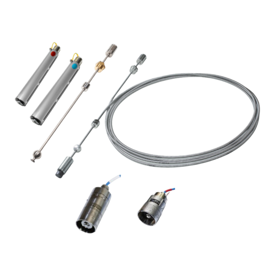
Visy probes
Hide thumbs
Also See for VISY-X:
- Technical documentation manual (34 pages) ,
- Technical documentation manual (16 pages) ,
- Technical documentation manual (16 pages)


Need help?
Do you have a question about the VISY-X and is the answer not in the manual?
Questions and answers