fafnir TORRIX Technical Documentation Manual
The magnetostrictive level sensor
Hide thumbs
Also See for TORRIX:
- Technical documentation manual (40 pages) ,
- Technical documentation manual (48 pages)
Table of Contents

Related Manuals for fafnir TORRIX


Summary of Contents for fafnir TORRIX
- Page 1 Technical Documentation TORRIX Version 5.5 The magnetostrictive level sensor Edition: 2023-05 Version: Art. no.: 350335 FAFNIR GmbH • Schnackenburgallee 149 c • 22525 Hamburg • Germany • T.: +49 /40 / 39 82 07-0 • Web: www.fafnir.com...
-
Page 2: Table Of Contents
Connection Diagrams ......................... 10 5.1.1 Wiring diagram TORRIX ........................10 5.1.2 Wiring diagram TORRIX Ex ....................... 10 Length of the connection cable (TORRIX 4 … 20 mA variants) ........... 11 Wiring ............................... 12 5.3.1 Cable gland ............................12 5.3.2 M12 Connection ........................... 13 Adjustment ...................... - Page 3 10.6 Petroleum & Explosives Safety Organisation (PESO) Approval .......... 49 © Copyright: Reproduction and translation are permitted solely with the written consent of the FAFNIR GmbH. The FAFNIR GmbH reserves the right to carry out product alterations without prior notice.
-
Page 4: Characteristics
Technical documentation TORRIX M12, art. no. 350164 The TORRIX supplies a 4 … 20 mA output signal that is configured using buttons in the probe head, or supplies a digital output signal as HART protocol. Probe lengths are possible from ®... -
Page 5: Safety Instructions
Safety Instructions The TORRIX is used for level and interface measurement of liquids in containers. Only use the sensor for this purpose. The manufacturer accepts no liability for any form of damage resulting from improper use. Observe and follow all safety notes and the operating instruc- tions. -
Page 6: Design And Function
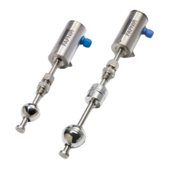
Design and Function The level sensors consist of a probe head (1) and a probe tube (4) made of stainless steel. On the probe tube is a screw-in unit (3) (cutting ring fitting or ferrule fitting) for height- adjustable mounting in the container or a flange for fixed installation or the probe tube is mounted outside the container on a Bypass. -
Page 7: Torrix Types
∅ 12 Probe tube ∅ 12 Float Float Adjusting Adjusting ring ring TORRIX (with screw-in unit) TORRIX Flange TORRIX Bypass Figure 2: TORRIX Types The TORRIX Bypass type is supplied without process connection or float. Design and Function Page 4/50... -
Page 8: Mounting
Mounting This section describes how to install the level sensor depending on the type of the device (see the following figures). For the installation and maintenance of the sensors, all national Regulations as well as the generally accepted rules of engineering and this manual must be observed. -
Page 9: Mounting With Screw-In Unit
Mounting with screw-in unit 1 – Screw-in unit 2 – Union nut 3 – Screw-in thread 4 – Probe tube 5 – Float 6 – Adjusting ring Figure 3: Mounting with screw-in unit Dismantling the floats is only necessary if the floats do not fit through the mounting hole in the tank. -
Page 10: Mounting With Flange
Mounting with flange Because of the risk of bending, the TORRIX Flange must not be held by the probe tube. The bolts or nuts and the seals are the responsibility of the operating company and must be selected depending on the fluid. - Page 11 TORRIX Bypass TORRIX Bypass Abstand Sondenrohr zu Distance between probe tube and float centre: Schwimmermitte: max. Abstand max. distance depends on the bypass float abhängig vom Bypass-Schwimmer max. max. Magnet position Bypass float Magnetposition Bypass-Schwimmer Sondenrohr spannungsfrei Probe tube tension-free...
-
Page 12: Electrical Connection
For TORRIX Ex… versions, the technical data of the EU-Type Examination Cer- tificate and the instructions must be observed (see appendix). In the intrinsically safe version, the TORRIX Ex level sensor may be connected in potentially explosive atmospheres only to associated equipment that have been certified by a recognised inspection authority. -
Page 13: Connection Diagrams
4...20 mA 4 … 20 mA 4...20 mA Line resistances Leitungswiderstände Power Supply Hilfsenergie Figure 7: Wiring diagram TORRIX Ex Power supply: U = 30 VDC Minimum supply voltage: U = 8 VDC Maximum current consumption: I = 21.5 mA... -
Page 14: Length Of The Connection Cable (Torrix 4
Length of the connection cable (TORRIX 4 … 20 mA variants) The cable (length and cross-section) must be chosen so that the supply voltage will not fall below the sensor-specific minimum voltage (U ) for the level sensor in the case of the highest current consumption (I The maximum resistance (supply voltage ÷... -
Page 15: Wiring
Wiring The level sensors may only be wired with the power disconnected. 5.3.1 Cable gland The connection terminals and adjustment buttons are located inside the probe head of the level sensor and protected by the cover. For the wiring of the level sensor, proceed as follows: Unscrew probe head cover (1) using an open-ended spanner. -
Page 16: M12 Connection
Pin 4 Pin assignment of the M12 female connector of the FAFNIR connection cable The connection cable between the TORRIX … and the associated equipment must have the following properties: 2-wire unshielded cable • For Ex applications colour blue or marked blue (cable for intrinsically safe power •... -
Page 17: Adjustment
Adjustment of the measuring span on the TORRIX The adjustment of the 4 mA and 20 mA measuring points on the TORRIX level sensor can be done with a green (2) and a red (3) button and the green LED (light emitting diode) in the terminal housing of the probe head. - Page 18 To define a reference point: Move the float to the desired reference point − Briefly (0.1 to 2 seconds) press the green button (2) to define a current consump- − tion of 4 mA at this position Briefly (0.1 to 2 seconds) press the red button (3) to define a current consumption −...
-
Page 19: Adjustment Of The Measuring Span With The Pc
The configuration with the PC must only be done outside the potentially explo- sive area. To connect the TORRIX to the PC, the FAFNIR USB adapter [TORRIX] and the M12 adapter are required (item no. 900223): Unscrew probe head cover (1) using an open-ended spanner... -
Page 20: Current Consumption In Failure Mode
21.5 mA but this value can also be set to 3.6 mA. 6.2.1 Adjustment of the current consumption on the TORRIX To configure the current consumption in failure mode (see Figure 10). Unscrew probe head cap (1) using an open-ended spanner. -
Page 21: Adjustment Of The Current Consumption With The Pc
6.2.2 Adjustment of the current consumption with the PC The current consumption in failure mode can be adjusted using the TORRIX Configuration Tool on a PC, see technical documentation: TORRIX Configuration Tool, art. no. 350258 The configuration with the PC must only be done outside the potentially explo- sive area. -
Page 22: Maintenance
Return Shipment Before returning any FAFNIR equipment, the Return Material Authorization (RMA) from FAFNIR customer service is required. Please contact your account manager or the customer service to receive the instructions on how to return goods. The return of FAFNIR products is only possible after approval by the FAFNIR customer service. -
Page 23: Technical Data
Technical Data Further technical data you also find in the EU-Type Examination Certificate and in the instructions, see the appendix of this manual. TORRIX in version 5.5 from device number 30000 Electrical connection 2-wire terminal 3.8 … 20.5 mA current consumption for measured value output 3.6 mA or 21.5 mA current consumption in the event of a fault... - Page 24 Accuracy Linearity better than ±0.2 mm or ±0.01 %, Digital component better than ±0.001 % per K NT/LT Repetition accuracy better than 0.05 mm Resolution better than 10 µm Accuracy Linearity better than ±0.5 mm or ±0.025 %, Digital component better than ±0.01 % per K HT/HHT Repetition accuracy better than 0.1 mm...
-
Page 25: Floats
Floats The float is an essential component of the level sensor that must be matched to the medium in respect of density, pressure resistance and material durability. The following floats are exchangeable and can be ordered separately. Other float types and materials are available on request. -
Page 26: List Of Figures
Figure 3: Mounting with screw-in unit ......................6 Figure4: Tightening the compression fitting ..................... 6 Figure 5: Installation on the bypass......................8 Figure 6: Wiring diagram TORRIX ......................10 Figure 7: Wiring diagram TORRIX Ex......................10 Figure 8: Wiring..............................12 Figure 9: Removable screw terminal ...................... -
Page 28: Eu-Type Examination Certificate
Directive 2014/34/EU Certificate Number TÜV 99 ATEX 1496 X Issue: for the product: Filling level sensors type VISY-Stick … and type TORRIX Ex… of the manufacturer: FAFNIR GmbH Address: 22525 Hamburg Germany Order number:... - Page 29 Issue 03 (15) Description of product: The filling level sensors type VISY-Stick … and type TORRIX Ex… are used for continuous measurement of liquid levels within potentially explosive areas. Floaters are used to detect the fluid levels. These slide on a sensor tube. For interface or water detection, a second float can be mounted on the sensor tube.
- Page 30 VISY-Stick … Flex … • • VISY-Stick … Advanced RS485 VISY-Stick … Flex RS485 • TORRIX Ex …-A • TORRIX Ex … Flex • • TORRIX Ex … PL TORRIX Ex C…-A • TORRIX Ex C… Flex • TORRIX Ex C… PL •...
- Page 31 Electrical data: VISY-Stick …; VISY-Stick (Flex) Temp; TORRIX Ex SC…; VISY-Stick Advanced …; VISY-Stick … Flex …; TORRIX Ex SC…-A; TORRIX Ex SC… Flex and TORRIX Ex SC… PL: Signal and power supply In type of protection intrinsic safety Ex ia IIC/IIB/IIIC...
- Page 32 VISY-Stick …; VISY-Stick (Flex) Temp; TORRIX Ex SC…; VISY-Stick Advanced …; VISY-Stick … Flex …; TORRIX Ex SC…-A; TORRIX Ex SC… Flex and TORRIX Ex SC… PL: For EPL Ga or EPL Ga/Gb or EPL Gb, the permissible temperature range depending on the...
- Page 33 TORRIX Ex RS485…; TORRIX Ex TAG…; TORRIX Ex XT…; VISY-Stick … Advanced RS485; VISY-Stick … Flex RS485; TORRIX Ex …-A; TORRIX Ex … Flex; TORRIX Ex … PL; TORRIX Ex C…-A; TORRIX Ex C… Flex; TORRIX Ex C… PL; TORRIX Ex RS485…-A;...
- Page 34 The equipment is suitable for dusts with an ignition temperature of more than 270 °C under a dust layer of 5 mm (glow temperature). TORRIX Exd XT…; TORRIX Exd …-A; TORRIX Exd … Flex and TORRIX Exd … PL: For EPL EPL Ga/Gb or EPL Gb, the permissible temperature range can be taken from the...
- Page 35 6. For EPL Ga/Gb applications the whole device filling level type VISY-Stick … resp. type TORRIX Ex has to be mounted in a way that allows an installation that results in a sufficiently tight joint (IP66 or IP67) or a flameproof joint (IEC 60079-1) in the direction of the less endangered area.
-
Page 36: Instructions
The filling level sensors TORRIX Ex … can be produced with different interfaces. These are, for example, interfaces "4 … 20 mA" (TORRIX Ex … and TORRIX Ex C…), "RS-485" (TORRIX Ex RS485…) or TAG (TORRIX Ex TAG…). The TORRIX Ex... - Page 37 Only with the TORRIX Ex ... with screw terminals the opening of the sensor head is planned. Further disassembly may damage the filling level sensor and void its approval.
- Page 38 For the filling level sensors with connection terminals, the terminal designation are "+" and "-" and additionally "A" and "B" for the type TORRIX Ex… XT… ("+" and "-" are added for the type TORRIX Exd … for the terminal block "Heater").
- Page 39 Ex marking: TORRIX Ex … / TORRIX Ex C… / TORRIX Ex RS485… / TORRIX Ex SC… / TORRIX Ex TAG… / TORRIX Ex XT… / VISY-Stick … / VISY-Stick RS485… / VISY-Stick (Flex) Temp / VISY-Stick (Flex) Temp RS485 II 1 G Ex ia IIC T6…T1 Ga...
- Page 40 Table 2: Electrical input data of intrinsic safe filling level sensors The voltage for the type TORRIX Exd … is from 12 V to 50 V (U = 253 V). The current is from 4 mA to 20 mA (Error mode: 3.6 mA / 21.5 mA) respectively 10 mA when using RS-485.
- Page 41 TORRIX Ex … / TORRIX Ex C… / TORRIX Ex RS485… / TORRIX Ex TAG… / TORRIX Ex XT… / VISY-Stick … RS485 For use in EPL Ga, EPL Ga/Gb and EPL Gb Temperature class ≤ 100 mA: -40 °C … +40 °C -40 °C …...
- Page 42 2. When using Titanium Floats or Sump Environmental Sensors, the risk of ignition due to impact or friction shall be avoided. 3. The flameproof joints at type TORRIX Exd … are not intended to be repaired. Page 7/7 FAFNIR GmbH...
-
Page 47: Sil 2 Safety Manual
It must be ensured that there are no strong magnetic fields in the area of the probe tube. In addition, the safe use with adhering liquids is not guaranteed. Page 1/5 FAFNIR GmbH • Schnackenburgallee 149 c • 22525 Hamburg • Tel.: +49 / (0)40 / 39 82 07-0 • www.fafnir.de • info@fafnir.de... - Page 48 Magnetostrictive level and environmental sensor with up to five temperature sensors in the sensor tube VISY- Volume Information System Type code III.a2: Level sensor VISY-Stick … Page 2/5 FAFNIR GmbH • Schnackenburgallee 149 c • 22525 Hamburg • Tel.: +49 / (0)40 / 39 82 07-0 • www.fafnir.de • info@fafnir.de...
- Page 49 Before putting into service, all devices must be checked of right installation and connection. The elec- trical supply, as well of connected devices, must be checked. Page 3/5 FAFNIR GmbH • Schnackenburgallee 149 c • 22525 Hamburg • Tel.: +49 / (0)40 / 39 82 07-0 • www.fafnir.de • info@fafnir.de...
- Page 50 Page 4/5 FAFNIR GmbH • Schnackenburgallee 149 c • 22525 Hamburg • Tel.: +49 / (0)40 / 39 82 07-0 • www.fafnir.de • info@fafnir.de...
- Page 51 Table IV: Safety related codes Additional requirements for software elements There are no requirements for software elements. Page 5/5 FAFNIR GmbH • Schnackenburgallee 149 c • 22525 Hamburg • Tel.: +49 / (0)40 / 39 82 07-0 • www.fafnir.de • info@fafnir.de...
-
Page 52: Petroleum & Explosives Safety Organisation (Peso) Approval
Nagpur - 440006 E-mail : explosives@explosives.gov.in Phone/Fax No : 0712 -2510248, Fax-2510577 Approval No : A/P/HQ/MH/104/6555 (P479308) Dated : 22/09/2020 M/s. FAFNIR GmbH, Scnackenburgallee 149 c,Hamburg 22525 GERMANY Sub : Approval of Filling Level Sensors. under Petroleum Rules 2002- Regarding. - Page 53 9/30/2020 (e) Protection level. 4) A certificate to the effect that the equipment has been manufactured strictly in accordance with the drawing referred to in the TUV NORD CERT GmbH Test report and is identical with the one tested and certified at TUV NORD CERT GmbH shall be furnished with each equipment.
- Page 54 Blank Page...
- Page 55 Blank Page...
- Page 56 FAFNIR GmbH Schnackenburgallee 149 c 22525 Hamburg, Germany T: +49 / 40 / 39 82 07– 0 E-mail: info@fafnir.com Web: www.fafnir.com...
Need help?
Do you have a question about the TORRIX and is the answer not in the manual?
Questions and answers