Table of Contents

Related Manuals for fafnir VISY-TD


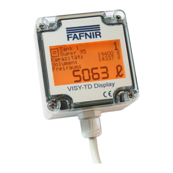
Summary of Contents for fafnir VISY-TD
- Page 1 Technical Documentation VISY-X VISY-TD Display (Truck Driver Display) Edition: 2022-10 Version: 4 Art. no.: 350169 FAFNIR GmbH • Schnackenburgallee 149 c • 22525 Hamburg Germany • T.: +49 /40 / 39 82 07-0 • Web: www.fafnir.de...
-
Page 2: Table Of Contents
Table of Contents Characteristics ......................1 Safety Instructions ....................1 Design and Function .................... 2 Tank Data .............................. 2 Error Display ............................3 Icons ................................ 3 Installation ......................4 Mounting ............................... 4 Electrical Connection ........................4 Communication........................... 6 External Switching Contact ......................7 Configuration ............................ - Page 3 © Copyright: Reproduction and translation are permitted solely with the written consent of the FAFNIR GmbH. The FAFNIR GmbH reserves the right to carry out product alterations without prior notice. Table of contents...
-
Page 4: Characteristics
Safety Instructions The VISY-TD Display is used to display the ullage determined by the VISY-X system in the tank up to the maximum filling level (capacity). In addition, the current volume is also displayed. -
Page 5: Design And Function
In the operating mode “automatic” (default), the VISY-TD Display is permanently activated and it switches to the next tank automatically. In the operating mode "manual", the VISY-TD Display is activated by pressing a switching contact and the data of the first tank is displayed. Repeatedly pressing the switching contact switches to the tank with the next higher tank number. -
Page 6: Error Display
Technical documentation VISY-Command…, art. no. 207184 Icons The icons described in the following are used by the VISY-TD Display to indicate the various states. No level change The level (the volume) of the displayed tank is currently not changing (no dispens- ing and no delivery). -
Page 7: Installation
Installation Mounting The VISY-TD Display should be mounted at eye level for better readability. Installation is recommended behind a glass pane inside the building. The VISY-TD Display can be attached to the glass pane by using the included Velcro fasteners. The housing cover does not need to be removed for the mounting. - Page 8 Power supply The included 5 V power supply unit is required for voltage supply of the VISY-TD Display and must be installed in the VISY-Command. For installation this power supply unit is clicked into the available top hat rail in the VISY-Command.
-
Page 9: Communication
Communication The communication between the VISY-TD Display and the VISY-Command is performed via a galvanically isolated RS485 interface. The communication lines of the VISY-TD Display are connected to the extension interface of the VISY-Command central unit. 3-wire lines with interface ground are recommended to increase the interference resistance for this connection. -
Page 10: External Switching Contact
Button, connection 2 Connection 2 Table 4: Pin assignment of the VISY-TD Display Configuration For the VISY-TD Display with firmware V1.0.1.255 and higher a configuration menu is available. 4.5.1 Operation The operation within the configuration menu is triggered by an external switching contact. -
Page 11: Display
4.5.2 Display Display of the main menu Main menu Closing the configuration Menu items available in the menu Figure 5: Display of the main menu Display of the sub-menu (in this case: tank selection) Sub-menu Active menu item Return to the main menu Menu items available in the menu Figure 6: Display of a sub-menu Always only a maximum of 3 menu items can be shown in the display. -
Page 12: Menu Structure
4.5.3 Menu Structure The configuration menu of VISY-TD Display has the following structure: Main Menu ➤ German ➤ English (default) ➤ Español ➤ Language Français ➤ Italiano ➤ Português ➤ Pусский Tank Selection ➤ All tanks (default) (all tanks configured in VISY- Command are displayed) ➤... -
Page 13: Error Messages
Return Shipment Before returning any FAFNIR equipment, the Return Material Authorization (RMA) from FAFNIR customer service is required. Please contact your account manager or the custom- er service to receive the instructions on how to return goods. The return of FAFNIR products is only possible after approval by the FAFNIR customer service. -
Page 14: Technical Data
List of tables Table 1: 7-pole connection cable assignment ..................4 Table 2: Voltage supply of the VISY-TD Display ..................5 Table 3: Communication lines of the VISY-TD Display ................. 6 Table 4: Pin assignment of the VISY-TD Display ..................7... - Page 16 FAFNIR GmbH Schnackenburgallee 149 c 22525 Hamburg, Germany T: +49 / 40 / 39 82 07-0 E-mail: info@fafnir.com Web: www.fafnir.com...
Need help?
Do you have a question about the VISY-TD and is the answer not in the manual?
Questions and answers