Woodward MicroNet TMR 5009FT Product Manual
Fault-tolerant steam turbine control, hmi interface manual
Hide thumbs
Also See for MicroNet TMR 5009FT:
- Product manual (148 pages) ,
- Installation and hardware manual (95 pages)

Subscribe to Our Youtube Channel
Related Manuals for Woodward MicroNet TMR 5009FT


Summary of Contents for Woodward MicroNet TMR 5009FT
- Page 1 Product Manual 26518V4 (Revision A) Original Instructions ® MicroNet TMR 5009FT Fault-Tolerant Steam Turbine Control HMI Interface Manual Manual 26518 consists of 4 volumes (26518V1, 26518V2, 26518V3, 26518V4). Volume 4...
- Page 2 Woodward reserves the right to update any portion of this publication at any time. Information provided by Woodward is believed to be correct and reliable. However, no responsibility is assumed by Woodward unless otherwise expressly undertaken.
-
Page 3: Table Of Contents
Manual 26518V4 MicroNet TMR 5009FT Contents ................ ARNINGS AND OTICES .......... LECTROSTATIC ISCHARGE WARENESS ................ EGULATORY OMPLIANCE 1. G ............1 HAPTER ENERAL NFORMATION 2. D ................2 HAPTER ESCRIPTION 3. I ............. 4 HAPTER NSTALLATION ROCEDURE ... - Page 4 MicroNet TMR 5009FT Manual 26518V4 Illustrations and Tables Figure 2-1. 5009FT System ..................2 Figure 4-1. General Functions ................8 Figure 4-2. Main Menu ................... 9 Figure 4-3. Startup Curve Screen ................. 10 Figure 4-4. Start Sequence Screen ..............10 ...
-
Page 5: Warnings And Notices
Start-up On- and off-highway Mobile Applications: Unless Woodward's control functions as the supervisory control, customer should install a system totally independent of the prime mover control system that... -
Page 6: Electrostatic Discharge Awareness
Do not touch the components or conductors on a printed circuit board with your hands or with conductive devices. To prevent damage to electronic components caused by improper handling, read and observe the precautions in Woodward manual 82715 , Guide for Handling and Protection of Electronic Controls, Printed Circuit Boards, and Modules. -
Page 7: Regulatory Compliance
Manual 26518V4 MicroNet TMR 5009FT Regulatory Compliance Part number 8269-1012 is suitable for use in ordinary (non-hazardous) locations only. Field wiring must be rated at least 75 °C for operating ambient temperatures expected to exceed 50 °C. Peripheral equipment must be suitable for the location in which it is used. - Page 8 MicroNet TMR 5009FT Manual 26518V4 Woodward...
-
Page 9: Chapter 1. General Information
*—Modbus is a registered trademark of Schneider Automation Inc. Volume 4—provides details on installation and operation of the HMI operator control station, if provided with your system. The Woodward HMI™ Operator Interface was developed for use with the ® MicroNet TMR 5009FT Digital Governor for steam turbines, generators, and compressors. -
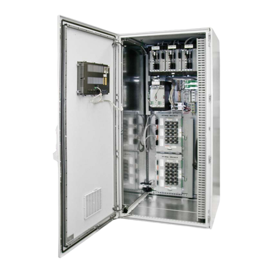
Page 10: Chapter 2. Description
Description The HMI Operator Interface is a touch screen workstation that functions as an ® enunciator and operator control panel for Woodward’s MicroNet TMR 5009FT digital control. This workstation allows an operator to remotely view operating points, vary control setpoints, and issue run mode commands. The HMI is comprised of an industrialized touch screen hardware package and Proficy iFix running on a Windows XP Embedded operating system. - Page 11 Manual 26518V4 MicroNet TMR 5009FT A selection of screens allows operators to monitor, control, and troubleshoot a system. These screens display: All controlling parameters Starting sequence status Turbine related information Generator related information Compressor related information ...
-
Page 12: Chapter 3. Installation Procedure
MicroNet TMR 5009FT Manual 26518V4 Chapter 3. Installation Procedure Introduction This touch screen workstation is designed for industrial applications for panel mounting. The front has an IP65 rating. The ambient temperature for operation is 5 to 55 °C (41 to 131 °F) and humidity conditions ranging 5 to 95% relative humidity (non-condensing). -
Page 13: Communications
Manual 26518V4 MicroNet TMR 5009FT Display - 17 in. Screen size, diagonal 430 mm (16.93 in.) Screen size, horizontal x vertical 337.92 x 270.34 mm Resolution 1280 x 1024 Type Resistive touch screen with serial/USB interface Brightness 350 Cd/m² Number of colors 16.7 million... -
Page 14: Printer Setup
MicroNet TMR 5009FT Manual 26518V4 If the 5009FT port/IP settings have been changed from the defaults, the HMI will not communicate unless the MicroNet TMR IP addresses as well as related iFix settings on the HMI computer have been modified as well. -
Page 15: Chapter 4. Operating Procedures
Manual 26518V4 MicroNet TMR 5009FT Chapter 4. Operating Procedures General Operating Procedures This chapter describes the options and features that are available through the HMI. This manual should not be used as an operational manual for the turbine ® control. Refer to Volume 1 of the MicroNet TMR 5009FT manual for more information on the operation and control functions of the 5009FT control. -
Page 16: General Screen Functions
(except Trend screens) signifying Local/Remote status. Refer to 'Local / Remote' of Volume 1 and 'CPU Communications' of Volume 3 of the MicroNet TMR 5009FT manuals for more information. Emergency Trip The 5009FT control is defaulted to not accept an emergency shutdown (ESD) command from the HMI. -
Page 17: Detailed Operating Procedures
Manual 26518V4 MicroNet TMR 5009FT General Functions Alarm button for alarm screen display. Alarm/Trip Status. HMI close (only on the Main Menu screen). SD button for an emergency shutdown. Norm SD button for a controlled shutdown. Time, Speed, HP valve, LP valve, and controlling parameters 1 and 2 are always available. -
Page 18: Startup Curve Screen
MicroNet TMR 5009FT Manual 26518V4 Startup Curve Screen This screen is used to start the turbine and ramp to rated speed or the minimum controlling speed. The Startup screen displayed will be different depending upon the configured values in the 5009FT control. Speed raise/lower buttons as well as a Go To button are available on this screen to control speed. -
Page 19: Turbine Run Screen
Dynamics Adjustment Adjustment to each controller's PID settings can only be performed through the CCT. To learn more on how to dynamically tune a steam turbine, reference Volume 1, of the MicroNet TMR 5009FT Control - Dynamic Adjustments. Woodward... -
Page 20: Monster View Screen
MicroNet TMR 5009FT Manual 26518V4 Monster View Screen (accessed from Turbine Run screen only) The Monster View Screen is a monitor only screen. This screen is provided for large views of the basic control parameters. Figure 4-6. Monster View Screen... -
Page 21: Analog Input/Output Screen
Manual 26518V4 MicroNet TMR 5009FT Analog Input/Output Screen Analog In / Out is monitor screen which displays configured analog inputs and outputs in units and mA format as well as speed sensors and actuator drivers. This screen is very useful for troubleshooting. -
Page 22: Controlled Shutdown
MicroNet TMR 5009FT Manual 26518V4 Controlled Shutdown The operator can initiate and abort a controlled shutdown from any screen. The shutdown can be monitored from the startup curves screen. Speed Control Screen Setpoints can be adjusted and from this screen. This screen is used to control and monitor speed and the HP and LP limiters. -
Page 23: Speed Dynamics
Manual 26518V4 MicroNet TMR 5009FT Speed Dynamics The Speed PID has two sets of dynamics; Off-Line and On-Line. The dynamics mode currently in use is displayed on the HMI. When the 5009FT changes from Off-Line to On-Line mode the HMI will also change to reflect the current mode. -
Page 24: Actuator Service Screen
MicroNet TMR 5009FT Manual 26518V4 Actuator Service Screen In order for the actuator valves to be stroked, several permissives must be met. The 5009FT control must be in a shutdown mode and the speed of the turbine must be 0 RPM. The stroking ENABLE/DISABLE button(s) remain hidden until the permissives are met. -
Page 25: Pid Control Screen
Manual 26518V4 MicroNet TMR 5009FT PID Control Screen The PID Control screen shows all of the configured 5009FT PID outputs and setpoints in a bar graph form. Setpoints can be adjusted and the enabled/disabled statuses of control functions can be monitored. This screen is particularly useful in viewing how the different control loops interact with one another. -
Page 26: Relay Output Status Screen
MicroNet TMR 5009FT Manual 26518V4 Relay Output Status Screen Relay configuration and status is displayed. The 5009FT control can be configured to allow an external DCS to control any of the 10 configurable Relays through a Modbus communication port. If Modbus relays are programmed the Modbus Relay screen can be accessed from this screen. -
Page 27: Extraction, Admission, Extr/Adm Control Screen
Manual 26518V4 MicroNet TMR 5009FT Extraction, Admission, EXTR/ADM Control Screen This screen contains functions used when enabling extraction, admission, or extr/adm. Figure 4-15. Extraction/Admission Control Screen Woodward... -
Page 28: Auxiliary Control Screen
MicroNet TMR 5009FT Manual 26518V4 Auxiliary Control Screen This screen contains functions used when enabling the Auxiliary Controller. Units displayed and the affect this controller has on the turbine operation will vary depending on how the 5009FT is configured. See the 5009FT manual Volume 1 for more information. -
Page 29: Cascade Control Screen
Manual 26518V4 MicroNet TMR 5009FT Cascade Control Screen This screen contains functions used when enabling the Cascade Controller. Units displayed and the affect this controller has on the turbine operation will vary depending on how the 5009FT is configured. See the 5009FT manual Volume 1 for more information. -
Page 30: Decoupling Control Screen
MicroNet TMR 5009FT Manual 26518V4 Decoupling Control Screen This screen contains functions used when enabling the Decoupling Controller. Units displayed and the affect this controller has on the turbine operation will vary depending on how the 5009FT is configured. See the 5009FT manual Volume 1 for more information. -
Page 31: Overspeed Test Screen
Manual 26518V4 MicroNet TMR 5009FT Overspeed Test Screen Testing of the mechanical and electrical overspeed devices can be monitored from this screen. To perform an overspeed test, refer to the 5009FT manual Volume 3. Figure 4-20. Overspeed Test Main Trends Screen This menu (similar to Main Menu) contains buttons to access trend screens for configured PIDs. -
Page 32: Trend Screens
MicroNet TMR 5009FT Manual 26518V4 Trend Screens Trend screens provide trend of setpoint, PID output, and control input captured at a one second scan rate. This screen also contains several of the parameters and adjustments on the corresponding dynamics screen. Display buttons, found below the trend graph, are used to show all or one of the available parameters. -
Page 33: Alarm Screen
Manual 26518V4 MicroNet TMR 5009FT Alarm Screen The Alarm Log screen displays 5009FT alarms and trips. Active alarms / trips appear in red with an asterisk next to the description. ALM ACK clears the asterisk and RESET will reset the alarm if it is no longer active, turning the text white. -
Page 34: Historical Alarm Screen
MicroNet TMR 5009FT Manual 26518V4 Historical Alarm Screen (accessed from ALARM screen only) The Alarm History screen is the same as the Alarm Log screen except that alarms cannot be cleared. The last 500 alarm conditions are displayed. The PRINTER button on this screen serves the same function as the button on the Alarm Log screen. - Page 36 Email and Website—www.woodward.com Woodward has company-owned plants, subsidiaries, and branches, as well as authorized distributors and other authorized service and sales facilities throughout the world. Complete address / phone / fax / email information for all locations is available on our website.
Need help?
Do you have a question about the MicroNet TMR 5009FT and is the answer not in the manual?
Questions and answers