Sign In
Upload
Manuals
Brands
Woodward Manuals
Control Systems
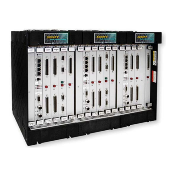
MicroNet TMR 5009FT
Woodward MicroNet TMR 5009FT Manuals
Manuals and User Guides for Woodward MicroNet TMR 5009FT. We have
3
Woodward MicroNet TMR 5009FT manuals available for free PDF download: Product Manual, Installation And Hardware Manual
Woodward MicroNet TMR 5009FT Product Manual (148 pages)
Fault-Tolerant Steam Turbine Control
Brand:
Woodward
| Category:
Control Systems
| Size: 1 MB
Table of Contents
Table of Contents
3
Warnings and Notices
6
Electrostatic Discharge Awareness
7
Chapter 1. General Information
8
Introduction
8
Control System Installation Procedure
8
Chapter 2. Description
10
General
10
Control Fault Tolerance
10
Figure 2-1. Double Exchange and Vote Structure
12
Figure 2-2. Fault Tolerant Analog Input
14
Figure 2-3. Fault Tolerant Discrete Input
15
Figure 2-4. Fault Tolerant Analog Output
16
Figure 2-5. Fault Tolerant Single Coil Actuator Output
18
Figure 2-6. Fault Tolerant Dual Coil Actuator Output
19
Figure 2-7. Fault Tolerant Discrete Output
20
5009 Control System Inputs and Outputs
22
Figure 2-8. Fault Tolerant Modbus Communication Ports
22
Figure 2-9. Proportional Controller Diagram
24
Figure 2-10. P Controller Diagram
25
Figure 2-11. PI Controller Diagram
25
Figure 2-12. PI Lag Controller Diagram
26
Figure 2-13. PI Lead Lag Controller Diagram
26
Figure 2-14. Three-Wire Transducer
27
Figure 2-15. Four-Wire Transducer
27
Figure 2-16. Five-Wire Transducer
28
Figure 2-17. Six-Wire Transducer
28
Configuration & Commissioning Tools (CCT) Programs
30
Figure 2-18. Configuration Toolkit Main Screen
30
Figure 2-19. Run and Service Toolkit Main Screen
31
Chapter 3. Control Functionality Overview
32
Control Overview
32
Figure 3-1. Typical Single Valve or Split Range Valve Steam Turbine
32
Figure 3-2. Split Range or Admission Type of Turbine Configuration
33
Figure 3-3. Extraction And/Or Admission Steam Turbine
34
Block Diagrams
35
Figure 3-4. Overview of 5009 Control System Functionality Notes
35
Figure 3-5. Single or Split-Range Turbine Configurations (Speed PID with Remote Setpoint)
36
Figure 3-6. Single or Split-Range Turbine Configurations (Auxiliary PID Configured as a Limiter)
37
Figure 3-7. Single or Split-Range Turbine Configurations (Auxiliary PID Configured as a Controller)
38
Figure 3-8. Extraction And/Or Admission Turbine Configurations (Auxiliary Configured as a Limiter)
39
Figure 3-9. Extraction And/Or Admission Turbine Configurations (Auxiliary Configured as a Controller)
40
Figure 3-10. Extraction And/Or Admission Turbine Configurations
41
Figure 3-11. Extraction And/Or Admission Turbine Configurations
42
Chapter 4. Application Notes
43
Overview
43
Example Applications
45
Figure 4-1. Pump or Compressor Discharge Pressure Control with Turbine Inlet Pressure Limiting
47
Figure 4-2. Pump or Compressor Suction Pressure Control with Turbine Inlet Pressure Limiting and Dual Coil Actuator
49
Figure 4-3. Exhaust Pressure Control with Generator Power Limiting and Plant Import/Export Limiting
51
Figure 4-4. Plant Import/Export Control with DRFD Servo Interface
54
Figure 4-5. Plant Import/Export Control with DRFD Servo Interface
56
Figure 4-6. Inlet Pressure Control with Isochronous Load Sharing Control in Island Mode
59
Figure 4-7. Import/Export Control or Exhaust Pressure Control with Isochronous Load Sharing in Island Mode
62
Figure 4-8. Inlet Pressure Control, Exhaust Pressure Control with Generator Power Limiting
65
Figure 4-9. Admission Steam Turbine Control with Bootstrap Start-Up
68
Figure 4-10. Plant Load and Steam Pressure Control Application
71
Chapter 5. Control Functionality
73
Introduction
73
Turbine Start Modes
73
Figure 5-1. Manual Start Mode Example
75
Figure 5-2. Semiautomatic Start Mode Example
76
Figure 5-3. Automatic Start Mode Example
77
Valve Limiters
79
Turbine Start Routines (Idle to Rated)
80
Figure 5-4. Automatic Start Sequence
81
Figure 5-5. Idle / Rated Start
82
Figure 5-6. Automatic Start Sequence
83
Speed Control Overview
85
Figure 5-7. Speed Control Functional Diagram
85
Speed PID Operational Modes
86
Figure 5-8. Speed Relationships
86
Figure 5-9. Speed PID Control Modes
90
Figure 5-10. Frequency and Unit Load Relationship
91
Figure 5-11. Load Sharing Logic
96
Extraction, Admission, or Extr/Adm Turbine Control
97
Figure 5-12. Ext/Adm Control Diagram
98
Figure 5-13. Coupled HP & LP Mode
106
Figure 5-14. Decoupled Inlet (HP) Mode
107
Figure 5-15. Decoupled Exhaust (LP) Mode
108
Figure 5-16. Decoupled HP&LP Mode
109
Figure 5-17. Priority Flow Diagram
110
Auxiliary Control
111
Figure 5-18. Auxiliary Control Overview
111
Cascade Control
115
Figure 5-19. Cascade Functional Diagram
115
Cascade Droop
117
Remote Cascade Setpoint
117
Seal GAS PID Control
118
Emergency Shutdown
119
Controlled Shutdown
120
Relays
121
Chapter 6. 5009 Control System Operation
123
Introduction
123
5009 System Power-Up
123
Valve / Actuator Calibration & Test
124
Turbine Start
125
Figure 6-1. Proportional Gain Setting Effects
128
Figure 6-2. Open Loop Proportional and Integral Response
129
Figure 6-3. Closed Loop Proportional and Integral Response
130
Figure 6-4. Integral Gain (Reset) Setting Responses
131
Figure 6-5. Closed Loop Proportional and Derivative Action
132
Figure 6-6. Derivative Setting Effects
133
Figure 6-7. Closed Loop Proportional, Integral and Derivative Action
134
General Field Tuning Guidelines
135
Figure 6-8. Typical Response to Load Change
135
Speed, Casc, Aux, and Ext/Adm Dynamics Adjustments
136
Overspeed Test Function
138
Operation Information
139
Chapter 7. Product Support and Service Options
142
Product Support Options
142
Product Service Options
142
Returning Equipment for Repair
143
Replacement Parts
144
Engineering Services
144
Contacting Woodward's Support Organization
144
Technical Assistance
145
Appendix A. Recommended Spares
146
Revision History
147
Advertisement
Woodward MicroNet TMR 5009FT Installation And Hardware Manual (95 pages)
Fault-Tolerant Steam Turbine Control Volume 2
Brand:
Woodward
| Category:
Control Unit
| Size: 2 MB
Table of Contents
Table of Contents
3
Warnings and Notices
5
Electrostatic Discharge Awareness
6
Regulatory Compliance
7
Chapter 1. General Information
9
Chapter 2. Hardware Description
10
Introduction
10
Main Control Chassis
10
System Power Supplies (PSM1 and PSM2)
11
Module Descriptions
12
Figure 2-1. Fault Tolerant Relay Outline Drawing
15
Figure 2-2. FT Relay Block Diagram
16
CCT - Touchpanel PC
17
Chapter 3. Mechanical Installation
19
Storage
19
Unpacking
19
Unit Location
19
Chapter 4. Electrical Installation
20
Introduction
20
Shields and Grounding
20
Figure 4-1. FTM103-1 and FTM103-2 Grounding Bars
21
Figure 4-2. FTM106-1 and FTM106-2 Grounding Bars
21
Figure 4-3. Shield Termination Diagram 1
21
Input Power
22
Figure 4-4. Shield Termination Diagram 2
22
Figure 4-5. Example MPU Interface Wiring Diagram (Ch 1 Shown)
24
Figure 4-6. Example 24 V Proximity Probe Wiring Diagram
24
Analog Inputs-TMR Analog Combo Module
26
Figure 4-7. MPU Pickup Voltage Vs Frequency
26
Analog Inputs-TMR 24/8 Analog Module
27
Figure 4-8. Example Analog Input Wiring Diagrams
27
Figure 4-9. Analog Input Wiring for a 24/8 Analog FTM
28
Analog Outputs-TMR Analog Combo Module
29
Analog Outputs-TMR 24/8 Analog Module
29
Figure 4-10. Example Analog Output Wiring Diagram
29
Actuator Outputs-TMR Analog Combo Module
30
Figure 4-11. Example Single Coil Actuator Wiring Diagram
30
Actuator Outputs-Actuator Controller Module
31
Figure 4-12. Example Dual Coil Actuator Wiring Diagram
31
Figure 4-13. 5009FT Compatible Position Feedback Schematics
32
Figure 4-12A. Example of Single Loop with Dual Coil and Two Lvdts Type (A-B)/(A+B) on Cylinder
33
Figure 4-12B. Example of Dual Loop with Dual Coil and Two Lvdts Type (A-B)/(A+B) on Cylinder Valve and Two Vdts Type (A-B)/(A+B) on Pilot Valve
34
FTM Contact Inputs (F/T Relay-Discrete In)
35
FTM Relay Outputs (F/T Relay Outputs)
36
Figure 4-14. Latent Fault Detection Verification Graph-18-32 VDC Circuitry
38
Figure 4-15. Latent Fault Detection Verification Graph-88-132 Vac Circuitry
39
Figure 4-16. Latent Fault Detection Verification Graph-100-150 VDC Circuitry
39
Figure 4-17. Jumper and Relay Location Diagram
41
Figure 4-18. FTM Labels
42
Communications
43
Figure 4-19. Example Relay Output Wiring Diagram
43
Control Wiring Diagrams
44
System Power-Up
44
Chapter 5. Troubleshooting and Module Replacement
46
Introduction
46
Main Power Supply (PSM1 and PSM2)
46
Kernel Power Supply (Kernel A/B/C: A1)
47
Replacing a 5009FT CPU While Unit Is Running
48
Analog and Discrete I/O Modules (Kernel A/B/C: A3-A5)
51
Channel Actuator Module (Kernel A/B: A6)
53
Termination Modules
53
Diagnostics
54
Figure 5-1. FTM Fuse Locations
54
System Troubleshooting Guide
56
Chapter 6. Hardware Specifications
59
Chapter 7. System Maintenance
61
Cables and Connections
61
Fans
61
Chapter 8. Micro Net Tmr ® Compatible Products
62
Figure 8-1. Micronet™ Compatible Products
62
DSLC™ Digital Synchronizer & Load Control
63
Figure 8-2. Inside View of Door
63
Figure 8-3. DSLC Mounting
64
Figure 8-4. DSLC Control
65
Real Power Sensor (RPS)
66
Figure 8-5. Real Power Sensor
67
Figure 8-6. Plant Wiring Diagram for the Real Power Sensor
68
Appendix A. Control Wiring Diagram
69
Appendix B. Standard Cabinet Layout Diagram
89
Revision History
93
Declarations
94
Woodward MicroNet TMR 5009FT Product Manual (36 pages)
Fault-Tolerant Steam Turbine Control, HMI Interface Manual
Brand:
Woodward
| Category:
Control Systems
| Size: 1 MB
Table of Contents
Table of Contents
3
Warnings and Notices
5
Electrostatic Discharge Awareness
6
Regulatory Compliance
7
Chapter 1. General Information
9
Chapter 2. Description
10
Figure 2-1. 5009FT System
10
Chapter 3. Installation Procedure
12
Introduction
12
Touchpanel Hardware
12
Communications
13
Printer Setup
14
Initial Setup
14
Setting the Time and Date
14
Chapter 4. Operating Procedures
15
General Operating Procedures
15
General Screen Functions
16
Figure 4-1. General Functions
16
Detailed Operating Procedures
17
Main Menu
17
Figure 4-2. Main Menu
17
Startup Curve Screen
18
Sequence Graphics
18
Figure 4-3. Startup Curve Screen
18
Figure 4-4. Start Sequence Screen
18
Turbine Run Screen
19
Figure 4-5. Turbine Run (Generator Unit)
19
Monster View Screen
20
Figure 4-6. Monster View Screen
20
Analog Input/Output Screen
21
Figure 4-7. Analog In/Out
21
Controlled Shutdown
22
Speed Control Screen
22
Figure 4-8. Speed Control
22
Speed Dynamics
23
Contact Input Screen
23
Figure 4-9. Contact Input
23
Actuator Service Screen
24
Actuator Status Screen
24
Figure 4-10. Actuator Service
24
Figure 4-11. Actuator Status
24
PID Control Screen
25
Figure 4-12. PID Control
25
Relay Output Status Screen
26
Steam Map Screen
26
Figure 4-13. Relay Outputs
26
Figure 4-14. Steam Map Screen
26
Extraction, Admission, EXTR/ADM Control Screen
27
Figure 4-15. Extraction/Admission Control Screen
27
Auxiliary Control Screen
28
Figure 4-16. Auxiliary Control Screen
28
Cascade Control Screen
29
Figure 4-17. Cascade Control Screen
29
Decoupling Control Screen
30
Generator Screen
30
Figure 4-18. DCPL Control Screen
30
Figure 4-19. Generator Screen
30
Overspeed Test Screen
31
Main Trends Screen
31
Figure 4-20. Overspeed Test
31
Figure 4-21. Trend Menu
31
Trend Screens
32
Figure 4-22. Extraction Trend Screen
32
Alarm Screen
33
Figure 4-23A. Alarm Screen
33
Historical Alarm Screen
34
Figure 4-23B. Alarm Screen
34
Advertisement
Advertisement
Related Products
Woodward MicroNet TMR 5009
Woodward MicroNet TMR 5009C
Woodward TM-25LP
Woodward TM-200LP
Woodward TM-100i
Woodward TM-1000LP
Woodward TM-55
Woodward TG-13E
Woodward TUG 4
Woodward TUG 404
Woodward Categories
Controller
Control Unit
Relays
Control Systems
Industrial Equipment
More Woodward Manuals
Login
Sign In
OR
Sign in with Facebook
Sign in with Google
Upload manual
Upload from disk
Upload from URL