Sign In
Upload
Manuals
Brands
Advantech Manuals
Motherboard
AIMB-276
User Manuals: Advantech AIMB-276 Mini-ITX Motherboard
Manuals and User Guides for Advantech AIMB-276 Mini-ITX Motherboard. We have
1
Advantech AIMB-276 Mini-ITX Motherboard manual available for free PDF download: User Manual
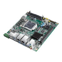
Advantech AIMB-276 User Manual (122 pages)
Brand:
Advantech
| Category:
Motherboard
| Size: 3 MB
Table of Contents
Table of Contents
9
Chapter 1 General Information
13
Introduction
14
Features
14
Specifications
14
System
14
Memory
14
Input/Output
14
Graphics
15
Ethernet LAN
15
Industrial Features
15
Mechanical and Environmental Specifications
15
Jumpers and Connectors
16
Board Layout: Jumper and Connector Locations
21
AIMB-276 Board Diagram
23
Safety Precautions
24
Jumper Settings
24
How to Set Jumpers
24
CMOS Clear (CMOS1)
25
Power Switch/Hdd Led/Smbus/Speaker Pin Header (JFP1)
25
Power LED and Keyboard Lock Pin Header (JFP2)
25
Watchdog Timer Output and OBS Beep (JWDT1+JOBS1)
26
(Jwdt1+Jobs1)
26
ATX/AT Mode Selection (PSON1)
26
LVDS Panel Voltage Selection (JLVDS1)
27
COM2 RI# Pin RI#/5V/12V Select (JSETCOM2_V1)
27
System Memory
27
Memory Installation Procedures
28
Cache Memory
28
Processor Installation
28
Chapter 2 Connecting Peripherals
29
Introduction
30
USB Ports (LAN1_USB12/LAN2_USB34/USB56/USB78/USB910)
30
Displayport1/2 (DP12) / High-Definition Multimedia Interface Connector (HDMI1)
31
Serial Ports (COM1~COM2)
32
CPU Fan Connector (CPU_FAN1)
33
System FAN Connector (SYSFAN1/2)
34
Power Switch/Hdd Led/Smbus/Speaker Pin Header (JFP1) & Power
35
LED and Keyboard Lock Pin Header (JFP2)
35
ATX Soft Power Switch (JFP1/PWR_SW)
35
Reset (JFP1/RESET)
35
Hdd Led (Jfp1/Hddled)
35
External Speaker (JFP1/SPEAKER)
35
DC Input Phoenix Connector (DCIN1)
36
SATA Signal & Power Connector (SATA1~SATA3 / SATA_PWR1~2)
37
HD Analog Audio Interface (AUDIO1, FPAUD1)
38
PCI-E X16 Slot (PCIEX16_1)
39
Low-Voltage Differential Signaling Interface/Embedded Display Port (LVDS_EDP1)
40
LVDS Backlight Inverter Power Connector (INV1)
41
NGFF M.2 B-Key & E-Key Connector (M2B1 & M2E1)
42
Audio Amplifier Output Connector (AMP1), BOM Optional
44
General Purpose I/O Pin Header (GPIO1)
45
SPI BIOS Flash Socket (SPI1)
46
SPI Programming Pin Header (SPI_CN1)
47
Low Pin Count Header (LPC1)
48
Case-Open Detect Connector (JCASE1)
49
CMOS Battery Connector (BAT1)
50
CPU Socket (CPU1)
51
DDR4 SO-DIMM Socket (DIMMA1, DIMMB1)
52
Chapter 3 BIOS Operation
53
Introduction
54
BIOS Setup
54
Main Menu
55
Advanced BIOS Features
55
Chipset Configuration Setting
69
System Agent (SA) Configuration
70
PCH-IO Configuration
74
Security Setting
79
Boot Setting
80
Save & Exit Configuration
81
Chapter 4 Software Introduction & Service
83
Introduction
84
Value-Added Software Services
84
Software API
84
Software Utility
86
Chapter 5 Chipset Software Installation Utility
87
Before You Begin
88
Introduction
88
Windows 10 Driver Setup
89
Chapter 6 VGA Setup
91
Introduction
92
Windows 10
92
Chapter 7 LAN Configuration
93
Introduction
94
Features
94
Installation
94
Windows 10 Driver Setup
95
Appendix A I/O Pin Assignments
97
Direct Current Input Connector (DCIN1)
98
Displayport1/2 (DP12)
98
High-Definition Multimedia Interface Connector (HDMI1)
99
Universal Serial Bus Port 3.1 Gen1 #7/ #8 (USB78)
99
Universal Serial Bus Port 3.1 Gen2 #1/ #2 (USB12)
100
Rj45 #1(Lan1)
100
Universal Serial Bus Port 3.1 Gen2 #3/ #4 (USB34)
101
Rj45 #2(Lan2)
101
Universal Serial Bus Port 3.1 Gen2 #6 (Type-C) (USB6)
101
Universal Serial Bus Port 3.1 Gen2 #5 (USB5)
102
HD Audio Interface (Analog) (AUDIO1)
102
Amplifier Connector (AMP1)
103
Front Panel Audio Header (FPAUD1)
103
CMOS Mode Selection (JCMOS1)
103
PCI Express X16 Slot (PCIEX16_1)
104
CMOS Battery Connector (BAT1)
106
Case Open Connector (JCASEOP_SW1)
106
Case Open Connector (JCASE1)
107
NGFF M.2 B-Key Connector for 2242/3042 Module (M2B1)
107
Universal Serial Bus Port 3.1 Gen1 #9/ #10 Box Header (USB910)
108
COM1 RI# Selection Pin Header (JSETCOM1_V1)
109
Serial ATA Interface Connector #1~#3 (SATA1~SATA3)
109
COM2 Pin Header ( S1.27MM) (COM2)
110
EDP/LVDS Backlight Inverter Power Connector (INV1)
110
COM1 Pin Header ( S1.27MM) (COM1)
111
Low Pin Count Interface Connector (LPC1)
111
Subscriber Identity Module Connector (SIM1)
112
LVDS VESA, JEIDA Format Selection Pin Header (JLVDS_VCON1)
112
Low-Voltage Differential Signaling Interface/Embedded Displayport (LVDS_EDP1)
113
Voltage Selection for JLVDS Connector (JLVDS1)
114
System Fan #1 Connector /System Fan #2 Connector (SYSFAN1/2)
114
Power LED and Keyboard Lock Pin Header (JFP2)
115
Watchdog Timer Output and OBS Beep (JWDT1+JOBS1)
115
CPU FAN Connector (CPUFAN1)
115
8-Bits General Purpose I/O Pin Header( S1.27MM) (GPIO1)
116
PWRBTN#/ RESET#/HDD LED/ Serial Bus from HW Monitor IC/Internal Buzzer / External Speaker Header (JFP1)
116
SPI BIOS Flash Socket (SPI1)
117
Serial ATA Interface Power Connector (SATA_PWR1/2)
117
AT/ATX Mode Selection (PSON1)
118
ATX Supported 3-Pin Header on Board (ATX_5VSB1)
118
NGFF M.2 E-Key Connector for 2230 Module (M2E1 )
119
Advertisement
Advertisement
Related Products
Advantech AIMB-273
Advantech AIMB-270
Advantech AIMB-275
Advantech AIMB-275 A2
Advantech AIMB-277
Advantech AIMB-285
Advantech AIMB-215L-S6B1E
Advantech AIMB-286F-00A1E
Advantech AIMB-286L-00A1E
Advantech AIMB-286G2-00A1E
Advantech Categories
Motherboard
Computer Hardware
Desktop
Touch Panel
Network Router
More Advantech Manuals
Login
Sign In
OR
Sign in with Facebook
Sign in with Google
Upload manual
Upload from disk
Upload from URL