Table of Contents
Advertisement
Quick Links
Advertisement
Table of Contents

Related Manuals for JMA SENA


Summary of Contents for JMA SENA
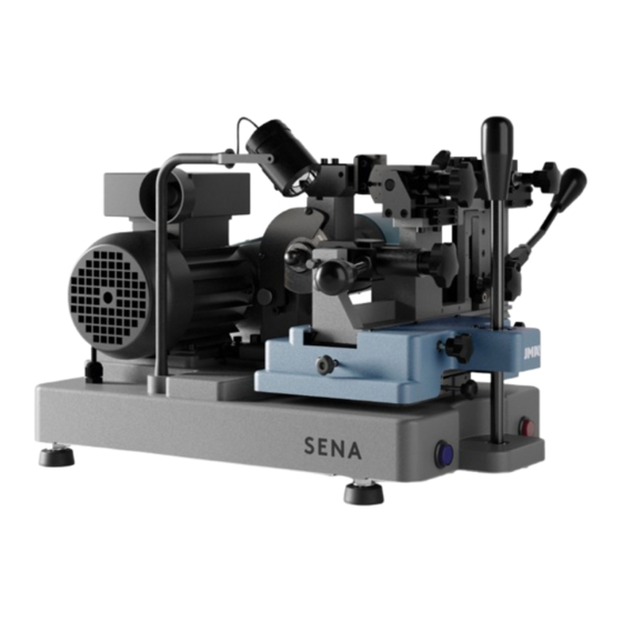
- Page 1 SENA INSTRUCTION MANUAL(V02)
-
Page 2: Table Of Contents
CONTENTS: PRESENTATION AND GENERAL ASPECTS ..............2 GENERAL POINTS........................2 TRANSPORT AND PACKING ....................2 IDENTIFICATION LABEL......................2 CHARACTERISTICS OF THE MACHINE................3 FAMILY OF KEYS ........................3 PARTS OF THE KEY........................5 TECHNICAL INFORMATION ....................5 MAIN ELEMENTS OF THE MACHINE ...................6 PRELIMINARY OPERATIONS AND WARNINGS..............7 2.5.1 Installing the levers .......................... -
Page 3: Presentation And General Aspects
PRESENTATION AND GENERAL ASPECTS GENERAL POINTS The SENA key cutting machine has been designed on the basis of the safety standards currently in force in the EU. The safety of the personnel involved in the handling of this type of machines can only be... -
Page 4: Characteristics Of The Machine
CHARACTERISTICS OF THE MACHINE The SENA key cutting machine is a professional semi-automatic key cutting machine. It has been prepared to cut single and double bladed bit keys, pump keys, Muel type keys and vertical groove keys. The machine’s design enables all the models of key mentioned to be cut without having to change the slide, only having to move the slide to the correct position. - Page 5 • Pump keys with flat or cylindrical stems, Muel type keys. • Keys with vertical grooves, wedge bit mortice and ADPLE-1-2-3-4 keys.
-
Page 6: Parts Of The Key
PARTS OF THE KEY 1. Head 2. Stem 3. Blade 4. Teeth TECHNICAL INFORMATION The main technical information is given below: Motor: Single phase, 2 speeds 2800-1400 rpm, 220V/ 50HZ, 0.55-0.37Kw Cutter: Hard metal ∅80 x 16 x1,5 mm. Clamps: 3 models Displacement: Guides with roller cage. -
Page 7: Main Elements Of The Machine
MAIN ELEMENTS OF THE MACHINE Cutter. 12. Lever to turn moving clamp for single / double bladed keys. 22. Pump key and vertical groove key fixed clamp. Brush. 13. Lever to move moving clamp for pump keys. 23. Pump key clamping fixed clamp knob. Tracer. -
Page 8: Preliminary Operations And Warnings
PRELIMINARY OPERATIONS AND WARNINGS. Place the machine on a solid table that will withstand the weight, bearing in mind that the line and machine voltage must be the same. The machine has been tested at our facilities before being sent out. Before starting up the machine and carrying out any operation, block the X and Y slides with controls 16 and 17. -
Page 9: Installing The Levers
Remember that the machine has two speeds: SPEED 1= STEEL 700 rpm SPEED 2 = BRASS 1400 rpm When starting up the machine, press the start button (7) and turn the motor selector to speed 1 or 2. Once the cutting operation has been completed, set the selector to the 0 position and press the button (7) again to completely switch off the machine. -
Page 10: Components And Functional Parts
COMPONENTS AND FUNCTIONAL PARTS 2.6.1 Accessories 1. ∅7x70 rod for changing the cutter. 2. Size 18 spanner. 3. Set of allen keys (2.5, 3, 4, 5, 6). 4. Side adjustment pieces. 5. ∅6x70 cutting depth adjustment rod. 6. Key stop plate. 7. -
Page 11: Electric Circuit
2.6.2 Electric circuit These are the main components of the electric and electronic circuits: 1. Socket. 2. Start switch with red light. 3. 2-speed motor. 4. Blue lighting switch. 5. Transformer. 6. Halogen lamp. -
Page 12: How To Operate The Machine
HOW TO OPERATE THE MACHINE MACHINE ADJUSTMENT The machine leaves our factory ready for use and you only need to check that it is working properly from time to time. N.B.: ANY OPERATIONS INVOLVING MOVING THE SLIDES, MAINTENANCE, CLAMPING AND RELEASING KEYS HAVE TO BE CARRIED OUT WITH THE MACHINE STOPPED. 3.1.1 Adjustment of the tracer point. - Page 13 • Repeat the same operation aligning the position of the slide (R2) with the reference point (S) to check that the clamp for pump keys and vertical groove keys is properly adjusted. To do this, use the adjustment rod W as shown in Fig.2 Fig.2 The tracer point has to be adjusted every time the cutter or tracer point is changed.
-
Page 14: Key Cutting
KEY CUTTING 3.2.1 Cutting bit keys. • Undo the knobs (15) and align the first position of the slide (R1) with the reference point (S). • Insert the keys into the clamps, taking are that the blade of the key butts up against the clamp’s key stop plate (T), as shown in Fig.3. -
Page 15: Cutting Pump Keys And Muel Type Keys
3.2.2 Cutting pump keys and Muel type keys. 3.2.2.1 Pump keys. • Undo the knobs (15) and align the second position of the slide (R2) with the reference point (S). • Insert the keys into the clamps, taking care that the blade of the key butts up against the front stop of the clamp, as shown in Fig.4. -
Page 16: Muel Type Keys
3.2.2.2 Muel type keys. • Undo the knobs (15) and align the second position of the slide (R2) with the reference point (S). • Undo the setscrew (T), turn the clamp 45º as shown in Fig.5. • Then secure the clamp in this position by turning the setscrew (T) so that the clamp is blocked. -
Page 17: Cutting Vertical Groove Keys, Wedge Bit Mortice And Adple1,2,3,4 Keys
3.2.3 Cutting vertical groove keys, wedge bit mortice and ADPLE1,2,3,4 keys. • Undo the knobs (15) and align the third position of the slide (R3) with the reference point (S). • Insert the keys to be cut into the clamp, making sure that the head of the key is parallel to the clamp. -
Page 18: Maintenance And Safety
MAINTENANCE AND SAFETY When carrying out any maintenance work it is necessary to adhere to the following requirements: 1. Never carry out any maintenance work with the machine in operation. 2. The electrical power cable must be unplugged. 3. The indications in this manual must be strictly adhered to. 4. -
Page 19: Changing The Tracer Point
CHANGING THE TRACER POINT Undo the screws (T), replace the tracer point and tighten the screws with the help of an allen key. Then check whether the machine is properly adjusted, by following the steps given in section 3.1.1. See Fig.1 and 2. ADJUSTING THE CLAMPS. -
Page 20: Pump Key And Vertical Groove Key Clamp Cutting Depth Adjustment
Fig.10 4.3.2 Pump key and vertical groove key clamp cutting depth adjustment. This adjustment is only necessary when changing the pump or vertical groove clamp. • Fit the two adjustment pieces (W) so that they butt up to the clamp, as shown in Fig 11. Move the rod (Q) forward so that the clamp is in the correct adjustment position. -
Page 21: Bit Key Clamp Side Adjustment
Fig.12 4.3.3 Bit key clamp side adjustment. This adjustment is only necessary when changing the single and double bladed bit key clamp • Put the two adjustment rods (W) right into the clamps, as shown in Fig 13. Move the rod (M) forward so that the clamp is in the correct adjustment position. -
Page 22: Pump Key And Vertical Groove Key Clamp Side Adjustment
Fig.13 Fig.14 4.3.4 Pump key and vertical groove key clamp side adjustment This adjustment is only necessary when changing the pump key and vertical groove key clamp. • Put the two adjustment rods (W) into the clamps, as shown in Fig 15. Move the rod (Q) forward so that the clamp is in the correct adjustment position. - Page 23 • Move the clamp to the right or left until the cutter turns and very gently touches the adjustment rod. Then, tighten up the screws (R, S) and setscrew nut (M, N) and the machine is adjusted. Fig.15 Fig.16...
-
Page 24: Tightening Or Replacing The Belt
TIGHTENING OR REPLACING THE BELT To check the tightness of the belt or to replace it, you need to follow the steps below: 1. Switch off the machine using the main switch and unplug the connection cable. 2. Undo the screws (T) securing the lower protection plate. 3. -
Page 25: Replacing The Lamp
REPLACING THE LAMP To replace the lamp, follow the steps given below: 1. Switch off the machine using the main switch and unplug the connection cable. 2. Remove the fixing ring. 3. Remove the lamp and undo the cable. 4. Connect the new lamp to the cable, insert it into its housing and secure with the fixing handle. -
Page 26: Waste Disposal
WASTE DISPOSAL Waste is understood to be any substance or object from human activities or natural cycles, that is no longer being used or not intended for any further use. PACKING • As the packing the machine comes in is made of cardboard, it can be recycled as packing. - Page 27 GOR-507 SENA I-2010 GOR-526 EC-201 GOR-114 GOR-114 GOR-502 EC-204 GOR-510 GOR-509 GOR-512 GOR-520...
- Page 28 SENA I-2010 GOR-525 GOR-525 GOR-522 GOR-511 GOR-508 GOR-525 GOR-507 GOR-525 GOR-506 GOR-527 GOR-506 GOR-527 GOR-508 GOR-507 GOR-511...
- Page 29 GOR-105 GOR-106 GOR-107...
Need help?
Do you have a question about the SENA and is the answer not in the manual?
Questions and answers