
Related Manuals for Alfa Laval GJ 18


Summary of Contents for Alfa Laval GJ 18
- Page 1 Instruction Manual Alfa Laval GJ 18 Covering: Standard Machines First published: 2019-April Original manual...
-
Page 3: Table Of Contents
8. Parts List and Service Kits ................8.1. AL GJ 18 View .................. -
Page 4: Ec Declaration Of Conformity
Address +1 610 408 9940 Phone no. hereby declare that Tank Cleaning Machine Alfa Laval GJ 18 Denomination Type From serial numbers SF-0100 to SF-9999 is in conformity with the following regulations and directives with amendments: - The Machinery Directive 2006/42/EC... -
Page 5: Safety
2 Safety Unsafe practices and other important information are emphasized in this manual. Warnings are emphasized by means of special signs. Always read the manual before using the tank cleaning machine! 2.1 Important Information WARNING Indicates that special procedures must be followed to avoid serious personal injury. CAUTION Indicates that special procedures must be followed to avoid damage to the tank cleaning machine. -
Page 6: Safety Precautions
Always read the technical data thoroughly. (See chapter 7 Technical Data.) Necessary precautions must be taken if leakage occurs as this can lead to hazardous situations. Always handle lye and acid with great care. When an Alfa Laval GJ is operating, there should be covers over every tank opening. -
Page 7: Introduction
(non-rotating turbine), and o-ring materials. The nozzles are available in several interchangeable sizes that range from 3/8-inch to 5/8-inch (9.5 mm to 15.9 mm). The Alfa Laval GJ 18 wash cycle time can be adjusted for special applications by changing the guide and/or nozzle size. Interchangeable stators and nozzle sizes are available for either low or high pressures and/or flow rates. -
Page 8: Installation
Read the instructions carefully and pay special attention to the warnings! Always check the tank cleaning machine before operation. 4.1 Unpacking/Delivery Step 1 CAUTION Check the delivery for: Alfa Laval cannot be held responsible for incorrect unpacking. 1. Complete Cleaning Machine 2. Delivery Note Step 2 Remove any packing materials. Step 3 Inspect the tank cleaning machine for visible transport damage. -
Page 9: Installation
The Alfa Laval GJ 18 can be suspended from the top of the tank via a flexible hose. The machine is designed to have balanced forces in order to keep it centered even while hanging. A flexible hose should not be used, however, when using the machine in any other orientation since the non-rigid hose will not maintain the unit’s position in the tank. - Page 10 Vessel Drainage If it is necessary to clean the floor of a vessel, any standing liquid will diminish the effectiveness of the Alfa Laval GJ 18 by covering any soils underneath. Wherever possible, the tank floor should be pitched toward the drain and the drainage opening should be large enough to eliminate or reduce any liquid buildup or puddling.
-
Page 11: Recycling Information
PD pump with the actual operating pressure, the actual operating pressure is dictated by the fixed flow rate of the pump and the Alfa Laval GJ 18 and plumbing system. If a PD pump is used, the Alfa Laval GJ 18 should be sized to first match the flow capability of the pump and, second, to not exceed the Alfa Laval GJ 18’s... -
Page 12: Operation
Initial Startup Every Alfa Laval GJ 18 shipped out is accompanied by a Birth Certificate. This document indicates how the unit performed in our testing tank before shipping, based on the operating conditions supplied to Alfa Laval. To ensure the longest possible life of the GJ 18, please verify the operating conditions and, most importantly, the machine’s cycle time. -
Page 13: Troubleshooting
Insufficient Flow Each Alfa Laval GJ 18 is configured to meet certain operating conditions outlined at the time of the initial sale, such as flow rate (GPM or m3/h), pressure (PSI or bar), temperature (℉ or ℃), chemical content of the wash fluid, cycle time, etc. If the Nozzles (pos. -
Page 14: Cleaning Solution Leakage
Pay attention to possible faults. Read the instructions carefully. 5.3 Cleaning Solution Leakage Cleaning Solution Leakage: The Alfa Laval GJ 18 is a self-flushing machine and thus has 2-3% leakage designed into the machine. Excessive leakage may indicate a larger issue. Worn Bearings & Seals Excessive leakage from the Tee Housing (pos. -
Page 15: Poor Cleaning Performance
Inadequate Drainage Ensure that the vessel drains the effluent (used wash fluid) as fast as it’s being sprayed in through the Alfa Laval GJ. The floor of the vessel should be sloped or pitched toward the drain and the drainage opening should be large enough to gravity- drain the effluent from the vessel. -
Page 16: Recommended Cleaning
5 Operation The Tank Cleaning machine is designed for cleaning in place (CIP). CIP = Cleaning in Place. Study the instructions carefully and pay special attention to the warnings! 5.5 Recommended Cleaning Step 1 Caustic danger! Always handle lye and acid with great care. Always use rubber gloves! Always use protective goggles! Step 2... -
Page 17: Maintenance
Always read the technical data thoroughly. (See chapter 7 Technical Data) Step 2 Recommended spare parts: Order service kits from the service kits list (See 8.8 Minor Service Kits & 8.9 Major Service Kits) Ordering spare parts: Contact your local Alfa Laval Sales company. -
Page 18: General Dismantling Setup
STORAGE The Alfa Laval GJ should be rinsed with clean water after each use to remove any foreign material or soft substances left in the machine that may harden during storage and cause the unit to seize or lock up. A clean water rinse through the Alfa Laval GJ 18 will also wash out any residues of chemical cleaners or recirculated wash water that could adversely affect the seals and O- rings during prolonged contact in storage. -
Page 19: General Dismantling
Maintenance Read the instructions carefully. The items refer to the parts list and service kits section. 6.3 General Dismantling Step 1 Inlet Collar Removal Loosen and remove the Inlet Collar Cap Screws (pos. 13) and matching Split Lock Washers (pos. 14) from the top of the Inlet Collar (pos. -
Page 20: Inspection And Service Of Components
If the unit is a pin drive machine, there will be a Bevel Gear Location Pin (pos. 15.2) in the corresponding hole in the Stem. If the unit is a clutch machine, the pin hole will be empty. Note: If you are unsure whether the unit is intended to be a pin or clutch drive, contact Alfa Laval for assistance. - Page 21 Maintenance Read the instructions carefully. The items refer to the parts list and service kits section. Drawing 9 Rotor Assembly Inspect the Rotor Shaft Central Bearing (pos. 7.2) that is installed in the Rotor (pos. 7.1) for chips, cracks, or excessive wear. The Bearing should protrude slightly from the bottom face of the Rotor.
- Page 22 Caution: If you suspect that the Gear Box requires service, proceed with caution. If at any time you do not feel completely comfortable servicing the Gear Box, contact Alfa Laval immediately. Drawing 14: Begin by holding the Gear Box upright to keep the internal components from unexpectedly spilling out.
- Page 23 Maintenance Read the instructions carefully. The items refer to the parts list and service kits section. Drawing 18 Nozzle Carrier Body Assembly Remove the Nozzles (pos. 36) from the Nozzle Carrier (pos. 33.1). Inspect the Stream Straighteners (pos. 37) inside the Nozzles for debris or damage.
-
Page 24: Reassembly
All Parts must be cleaned thoroughly before reassembling. Any deposits remaining on the parts can cause difficult disassembly the next time the Alfa Laval GJ 18 needs to be serviced. Also, it may cause misalignment of parts and the potential for premature failure. - Page 25 Maintenance Read the instructions carefully. The items refer to the parts list and service kits section. Drawings 8-12 Input Shaft Housing Assembly Drawing 12: Confirm that the Input Pinion Shaft Assembly is assembled, with no play between the parts. Drawing 11: Gently press the two Input Shaft Seals (pos. 11) into the top of the Input Shaft Seal Housing (pos. 9.1), applying pressure evenly around the seals during installation to prevent damage.
- Page 26 If the unit is a pin drive machine, there will be a Bevel Gear Location Pin (pos. 15.2) in the corresponding hole in the Stem. If the unit is a clutch machine, the pin hole will be left empty. Note: If you are unsure whether the unit is intended to be a pin or clutch drive, contact Alfa Laval for assistance.
- Page 27 Maintenance Read the instructions carefully. The items refer to the parts list and service kits section. Drawing 6, 2 Gear Train Assembly and Installation Drawing 6: Combine the subassemblies for the Input Shaft Housings (Drawings 8-12), the Gear Box (Drawings 14-17), and the Output Shaft Housing (Drawing 13).
-
Page 28: Technical Data
Inform personnel about the technical data. Technical Data The Alfa Laval GJ 18 Tank Cleaning Machine is a highly efficient machine at a range of pressures and flows. The instruction manual is part of the delivery. Read the instructions carefully. -
Page 29: Performance Data
7 Technical Data It is important to observe the technical data during installation, operation and maintenance. Inform personnel about the technical data. Performance Data 29 ... -
Page 30: Dimensions
7 Technical Data It is important to observe the technical data during installation, operation and maintenance. Inform personnel about the technical data. Dimensi o ns Dim ens io ns 13.27 9.84 12.76 4.84 6.84 12.78 14.61 NOTE 1: 2 1 / 2 ” NPT or 2 ½” BSP 30 ... -
Page 31: Parts List And Service Kits
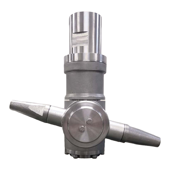
8 Parts List and Service Kits The Drawing shows Alfa Laval GJ 18 Tank Cleaning Machine. AL GJ 18 View GJ1800 31 ... -
Page 32: Assembly Drawings - 1
The Drawings show the Alfa Laval GJ 18 Tank Cleaning Machine. Assembly Drawings – 1 & 2 GJ1801 GJ1802 32 ... -
Page 33: Assembly Drawings - 3, 4
8 Parts List and Service Kits The Drawings show the Alfa Laval GJ 18 Tank Cleaning Machine. Assembly Drawings – 3, 4 & 5 GJ1803 GJ1804 GJ1805 33 ... -
Page 34: Assembly Drawings - 6, 7, 8, 9, 10, 11, 12
The Drawings show the Alfa Laval GJ 18 Tank Cleaning Machine. Assembly Drawings – 6, 7, 8, 9, 10, 11, 12 & 13 GJ1806 GJ1807 34 ... - Page 35 8 Parts List and Service Kits The Drawings show the Alfa Laval GJ 18 Tank Cleaning Machine. GJ1809 GJ1810 GJ1808 GJ1811 35 ...
- Page 36 The Drawings show the Alfa Laval GJ 18 Tank Cleaning Machine. GJ1813 GJ1812 36 ...
-
Page 37: Assembly Drawings - 14, 15, 16
8 Parts List and Service Kits The Drawings show the Alfa Laval GJ 18 Tank Cleaning Machine. Assembly Drawings – 14, 15, 16 & 17 GJ1814 GJ1815 37 ... - Page 38 The Drawings show the Alfa Laval GJ 18 Tank Cleaning Machine. GJ1816 GJ1817 38 ...
-
Page 39: Assembly Drawings - 18
8 Parts List and Service Kits The Drawings show the Alfa Laval GJ 18 Tank Cleaning Machine. Assembly Drawings – 18 & 19 GJ1818 GJ1819 39 ... -
Page 40: Parts List
PLANETARY OUTPUT SHAFT WASHER *Parts and assemblies are only assigned an Alfa Laval part number if they are available for individual sale. To purchase spare parts, or if you think you may need parts beyond those listed, please contact your local Alfa Laval sales company. - Page 41 GJ 4 STREAM STRAIGHTENER *Parts and assemblies are only assigned an Alfa Laval part number if they are available for individual sale. To purchase spare parts, or if you think you may need parts beyond those listed, please contact your local Alfa Laval sales company.
-
Page 42: Minor Service Kits
Minor Service Kits Article no: 9614714400 18EPDMKIT GJ 18 EPDM MINOR KIT Pos. no. Part No. Gamajet Part No. Description 9614712300 18131 LABYRINTH BEARING pcs. 9614713000 18145 OUTPUT SHAFT UPPER BEARING pcs. 18147 OUTPUT SHAFT LOWER BEARING pcs. 9614713200... -
Page 43: Major Service Kits
8 Parts List and Service Kits Major Service Kits Article no: 9614714401 18EPDMMAJKIT GJ 18 EPDM MAJOR KIT Pos. no. Part No. Gamajet Part No. Description 9614712300 18131 LABYRINTH BEARING pcs. 9614713000 18145 OUTPUT SHAFT UPPER BEARING pcs. 9614713200 18147 OUTPUT SHAFT LOWER BEARING pcs. - Page 44 © Alfa Laval Corporate AB This document and its contents are owned by Alfa Laval Corporate AB and protected by laws governing intellectual property and thereto related rights. It is the responsibility of the user of this document to comply with all applicable intellectual property laws. Without limiting any rights related to this document, no part of this document may be copied, reproduced or transmitted in any form or by any means (electronic, mechanical, photocopying, recording, or otherwise), or for any purpose, without the expressed permission of Alfa Laval Corporate AB.
Need help?
Do you have a question about the GJ 18 and is the answer not in the manual?
Questions and answers