
Subscribe to Our Youtube Channel
Related Manuals for VAMP VAMP 55


Summary of Contents for VAMP VAMP 55
- Page 1 VAMP 55 Voltage and frequency protection relay Operation and configuration instructions Technical description...
- Page 2 VM55.EN005...
-
Page 3: Table Of Contents
2.4.8. Configuration menu CONF ........31 2.4.9. Protocol menu Bus ..........32 2.4.10. Single line diagram editing ........35 2.4.11. Blocking and interlocking configuration ..... 35 3. VAMPSET PC software ............36 VM55.EN005 VAMP 24h support phone +358 (0)20 753 3264... -
Page 4: General
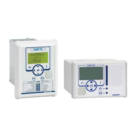
The VAMP 55 protection relay concept has two alternative casing layout designs: basic and slim fit. The VAMP 55S includes more compact casing than in the basic design. In the VAMP 55S, the same protection, measurement and control functions and communication interfaces are supported as in the basic 55 relays. -
Page 5: User Interface
Disconnecting a live circuit may cause dangerous voltages! Any operational measures must be carried out according to national and local handling directives and instructions. Carefully read through all operation instructions before any operational measures are carried out. VM55.EN005 VAMP 24h support phone +358 (0)20 753 3264... -
Page 6: Local Panel User Interface
2.1. Relay front panel The figure below shows, as an example, the front panel of the voltage and frequency protection relay VAMP 55 and the location of the user interface elements used for local control. Figure 2.1-1. Relay front panel 1. -
Page 7: Display
Figure 2.1.1-2 Sections of the LCD dot matrix display 1. Main menu column 2. The heading of the active menu 3. The cursor of the main menu 4. Possible navigating directions (push buttons) 5. Measured/setting parameter 6. Measured/set value VM55.EN005 VAMP 24h support phone +358 (0)20 753 3264... -
Page 8: Menu Navigation And Pointers
LINE VOLTAGES. 4. Further, each display holds the measured values and units of one or more quantities or parameters, e.g. U12max 23000 VAMP 24h support phone +358 (0)20 753 3264 VM55.EN005... -
Page 9: Keypad
Instructions about programming F1 / F2, see chapter 5.4 Function keys / F1 & F2 in the technical description. NOTE! The term, which is used for the buttons in this manual, is inside the brackets. VM55.EN005 VAMP 24h support phone +358 (0)20 753 3264... -
Page 10: Operation Indicators
ENTER key. The latched indicators and relays can also be reset via a remote communication bus or via a digital input configured for that purpose. VAMP 24h support phone +358 (0)20 753 3264 VM55.EN005... -
Page 11: Adjusting Display Contrast
6. Pushing the UP or DOWN key in any position of a submenu, when it is not selected, brings you directly one step up or down in the main menu. VM55.EN005 VAMP 24h support phone +358 (0)20 753 3264... - Page 12 7. Push the INFO key and then the ENTER key to give the password. 8. Push the INFO key to obtain additional information about any menu item. 9. Push the CANCEL key to revert to the normal display. VAMP 24h support phone +358 (0)20 753 3264 VM55.EN005...
- Page 13 1st positive sequence undervoltage stage U1<< 2nd positive sequence undervoltage stage U< 1st undervoltage stage U<< 2nd undervoltage stage U<<< 3rd undervoltage stage Uo> 1st residual overvoltage stage Uo>> 2nd residual overvoltage stage VM55.EN005 VAMP 24h support phone +358 (0)20 753 3264...
-
Page 14: Menu Structure Of Protection Functions
The general structure of all protection function menus is similar although the details do differ from stage to stage. As an example the details of the second overvoltage stage U>> menus are shown below. VAMP 24h support phone +358 (0)20 753 3264 VM55.EN005... - Page 15 “Configurator”. If no front panel button is pressed within five minutes and there is no VAMPSET communication, the force flag will be set to “Off” position. The forcing is explained in Chapter 2.3.4. VM55.EN005 VAMP 24h support phone +358 (0)20 753 3264...
- Page 16 Operating levels are explained in chapter 2.2.5. t>> 0.10s The total operation delay is set to 100 ms. This value can be edited if the operating level is at least “Operator”. VAMP 24h support phone +358 (0)20 753 3264 VM55.EN005...
- Page 17 SetGrp 1 The setting group has been 1. This line can be reached by pressing ENTER and several times the DOWN button. VM55.EN005 VAMP 24h support phone +358 (0)20 753 3264...
-
Page 18: Setting Groups
(the LEFT key is used when the active setting group is 2 and the RIGHT key is used when the active setting group is 1). Figure 2.2.3-2 Example of U>> setting submenu VAMP 24h support phone +358 (0)20 753 3264 VM55.EN005... -
Page 19: Fault Logs
(See Figure 2.2.4-2, Log2 = log two). The log two is selected by pressing the RIGHT key once. Figure 2.2.4-2 Example of selected fault log VM55.EN005 VAMP 24h support phone +358 (0)20 753 3264... -
Page 20: Operating Levels
Opening: Default password is 2 Setting state: Push ENTER Closing: The level is automatically closed after 10 minutes idle time. Giving the password 9999 can also close the level. VAMP 24h support phone +358 (0)20 753 3264 VM55.EN005... - Page 21 Get the serial number of the relay (Example: 12345) Send both the numbers to vampsupport@vamp.fi and ask for a password break. A device specific break code is sent back to you. That code will be valid for the next two weeks.
-
Page 22: Operating Measures
2. Confirm the operation by pushing the ENTER key. Toggling virtual inputs 1. Push the ENTER key. The previously activated object starts to blink. 2. Select the virtual input object (empty or black square) 3. The dialog opens VAMP 24h support phone +358 (0)20 753 3264 VM55.EN005... -
Page 23: Measured Data
U/VOLT. INTERRUPTS Previous interruption [ ] Total U/VOLT. INTERRUPTS Total duration of voltage interruptions [days, hours] Prev U/VOLT. INTERRUPTS Duration of previous interruption [s] Status U/VOLT. INTERRUPTS Voltage status [LOW; NORMAL] VM55.EN005 VAMP 24h support phone +358 (0)20 753 3264... -
Page 24: Reading Event Register
It is possible to set the order in which the events are sorted. If the “Order” -parameter is set to “New-Old”, then the first event in the EVENT LIST is the most recent event. VAMP 24h support phone +358 (0)20 753 3264 VM55.EN005... -
Page 25: Forced Control (Force)
10. Repeat the steps 1...4 to exit the Force function. 11. Push the CANCEL key to return to the main menu. NOTE! All the interlockings and blockings are bypassed when the force control is used. VM55.EN005 VAMP 24h support phone +358 (0)20 753 3264... -
Page 26: Configuration And Parameter Setting
ENTER key again. The parameter can now be set. When the parameter change is confirmed with the ENTER key, a [RESTART]- text appears to the top-right corner of the display. This means that auto-resetting is VAMP 24h support phone +358 (0)20 753 3264 VM55.EN005... -
Page 27: Parameter Setting
6. Push the ENTER key to accept a new value. If you want to leave the parameter value unchanged, exit the edit state by pushing the CANCEL key. Figure 2.4.1-1.Changing parameters VM55.EN005 VAMP 24h support phone +358 (0)20 753 3264... -
Page 28: Setting Range Limits
Recording time (Time) Pre trig time (PreTrig) Manual trigger (ManTrig) Count of ready records (ReadyRec) REC. CHANNELS Add a link to the recorder (AddCh) Clear all links (ClrCh) VAMP 24h support phone +358 (0)20 753 3264 VM55.EN005... -
Page 29: Configuring Digital Inputs Di
Trip and application specific alarm leds A, B, C, D, E, F, G and H (that is, the output relay matrix). NOTE! The amount of Trip and Alarm relays depends on the relay type and optional hardware. VM55.EN005 VAMP 24h support phone +358 (0)20 753 3264... -
Page 30: Configuring Analogue Outputs Ao (Option)
The relay includes several protection functions. However, the processor capacity limits the number of protection functions that can be active at the same time. VAMP 24h support phone +358 (0)20 753 3264 VM55.EN005... -
Page 31: Configuration Menu Conf
"". Daylight saving time for NTP synchronization (DST). Detected source of synchronization (SyScr). Synchronization message counter (MsgCnt). Latest synchronization deviation (Dev). VM55.EN005 VAMP 24h support phone +358 (0)20 753 3264... -
Page 32: Protocol Menu Bus
Communication error counter [Errors]. Communication time-out error counter [Tout]. Information of bit rate/data bits/parity/stop bits. This value is not directly editable. Editing is done in the appropriate protocol setting menus. VAMP 24h support phone +358 (0)20 753 3264 VM55.EN005... - Page 33 SPABUS address for this device [Addr]. This address has to be unique within the system. Bit rate [bit/s]. Default is "9600". Event numbering style [Emode]. Default is "Channel". For details see the technical description part of the manual. VM55.EN005 VAMP 24h support phone +358 (0)20 753 3264...
- Page 34 [Parity]. Address for this device [SlvAddr]. This address has to be unique within the system. Master's address [MstrAddr]. For further details see the technical description part of the manual. VAMP 24h support phone +358 (0)20 753 3264 VM55.EN005...
-
Page 35: Single Line Diagram Editing
Furthermore, the interlocking between objects can be configured in the same blocking matrix of the VAMPSET software. For more information, please refer to the VAMPSET manual (VMV.EN0xx). VM55.EN005 VAMP 24h support phone +358 (0)20 753 3264... -
Page 36: Vampset Pc Software
Optional hardware is required for Ethernet connection. There is a free of charge PC program called VAMPSET available for configuration and setting of VAMP relays. Please download the latest VAMPSET.exe from our web page www.vamp.fi. For more information about the VAMPSET software, please refer to the user’s manual with the code... - Page 37 5.2. Digital inputs ..............110 5.3. Virtual inputs and outputs ..........112 5.4. Function keys / F1 & F2 ..........113 5.5. Output matrix ..............114 5.6. Blocking matrix .............. 115 VM55.EN005 VAMP 24h support phone +358 (0)20 753 3264...
- Page 38 9.1.4. Trip contacts ............168 9.1.5. Alarm contacts ............. 168 9.1.6. Local serial communication port ....... 168 9.1.7. Remote control connection (option) ....168 9.1.8. Analogue output connection (option) ..... 169 VAMP 24h support phone +358 (0)20 753 3264 VM55.EN005...
- Page 39 9.4.2. Voltage sag & swell ..........175 9.4.3. Voltage interruptions ..........175 10. Abbreviations and symbols ..........176 11. Construction ............... 178 12. Order information ............... 180 13. Revision history ..............182 14. Reference information ............183 VM55.EN005 VAMP 24h support phone +358 (0)20 753 3264...
-
Page 40: Introduction
Easy configuration, parameterisation and reading of information via local HMI, or with a VAMPSET user interface. Easy connection to various automation systems due to several available communication protocols. Native IEC61850 implementation is available as option. VAMP 24h support phone +358 (0)20 753 3264 VM55.EN005... -
Page 41: Principles Of Numerical Protection Techniques
The main components are the energizing inputs, digital input elements, output relays, A/D converters and the micro controller including memory circuits. Further, a device contains a power supply unit and a human-machine interface (HMI). VM55.EN005 VAMP 24h support phone +358 (0)20 753 3264... - Page 42 Figure 1.2-3 shows a principle diagram of a single-phase overvoltage function. Figure 1.2-1 Principle block diagram of the VAMP hardware Figure 1.2-2 Block diagram of signal processing and protection software VAMP 24h support phone +358 (0)20 753 3264...
- Page 43 Technical description 1 Introduction 1.2 Principles of numerical protection techniques Figure 1.2-3 Block diagram of a basic protection function VM55.EN005 VAMP 24h support phone +358 (0)20 753 3264...
-
Page 44: Protection Functions
The blocking reason may be an active signal via the block matrix from other stages, the programmable logic or any digital input. Some stages also have inbuilt blocking logic. For more details about block matrix, see chapter 5.6. VAMP 24h support phone +358 (0)20 753 3264 VM55.EN005... - Page 45 Retardation time is the time a protection relay needs to notice, that a fault has been cleared during the operation time delay. This parameter is important when grading the operation time delay settings between relays. VM55.EN005 VAMP 24h support phone +358 (0)20 753 3264...
- Page 46 (the dashed 40 ms pulse in the figure). In VAMP devices the retardation time is less than 50 VAMP 24h support phone +358 (0)20 753 3264...
- Page 47 With zero hysteresis any noise in the measured signal or any noise in the measurement itself would cause unwanted oscillation between fault-on and fault-off situations. VM55.EN005 VAMP 24h support phone +358 (0)20 753 3264...
- Page 48 (dead band) acts according this figure. Figure 2.2-4. Behaviour of a less than comparator. For example in under- voltage and under frequency stages the hysteresis (dead band) acts according this figure. VAMP 24h support phone +358 (0)20 753 3264 VM55.EN005...
-
Page 49: List Of Protection Functions
U<<< >, U >> Zero sequence voltage protection f><, f>><< Overfrequency and underfrequency 81H/81L protection f<, f<< Underfrequency protection ∆f, ∆U, ∆φ Synchrocheck 50BF CBFP Circuit-breaker failure protection Prg1…8 Programmable stages VM55.EN005 VAMP 24h support phone +358 (0)20 753 3264... -
Page 50: Overvoltage Protection U> (59)
Switching between setting groups can be controlled by digital inputs, virtual inputs (mimic display, communication, logic) and manually. Figure 2.4-1 shows the functional block diagram of the overvoltage function stages U>, U>> and U>>>. VAMP 24h support phone +358 (0)20 753 3264 VM55.EN005... - Page 51 Pick-up value scaled to U>>> primary value U>, U>>, Pick-up setting relative to U U>>> t>, t>>, Definite operation time t>>> RlsDly Release delay (U> stage only) Hyster Dead band size i.e. hysteresis (default) VM55.EN005 VAMP 24h support phone +358 (0)20 753 3264...
- Page 52 Time stamp of the recording, date hh:mm:ss.ms Time stamp, time of day Maximum fault voltage EDly Elapsed time of the operating time setting. 100% = trip SetGrp Active setting group during fault VAMP 24h support phone +358 (0)20 753 3264 VM55.EN005...
-
Page 53: Volts/Hertz Over-Excitation Protection U F > (24)
The volts/hertz characteristics on the left depend on the frequency while the standard overvoltage function on the right is insensitive to frequency. The network frequency, 50 Hz or 60 Hz, is automatically adopted by the relay. VM55.EN005 VAMP 24h support phone +358 (0)20 753 3264... - Page 54 F = Editable when force flag is on Recorded values of the latest eight faults There are detailed information available of the eight latest faults: Time stamp, fault voltage, fault frequency, elapsed delay and setting group. VAMP 24h support phone +358 (0)20 753 3264 VM55.EN005...
- Page 55 Time stamp of the recording, date hh:mm:ss.ms Time stamp, time of day Fault value V/Hz Fault voltage Fault frequency EDly Elapsed time of the operating time setting. 100% = trip SetGrp Active setting group during fault VM55.EN005 VAMP 24h support phone +358 (0)20 753 3264...
-
Page 56: Undervoltage Protection U < (27P)
The self blocking can not be disabled. Initial self blocking When the voltage U has been below the block limit, the stages will be blocked until the pick-up setting has been reached. VAMP 24h support phone +358 (0)20 753 3264 VM55.EN005... - Page 57 Figure 2.6-1 Positive sequence under voltage state and block limit. Two independent stages There are two separately adjustable stages: U < and U <<. Both stages can be configured for definite time (DT) operation characteristic. VM55.EN005 VAMP 24h support phone +358 (0)20 753 3264...
- Page 58 F = Editable when force flag is on Recorded values of the latest eight faults There are detailed information available of the eight latest faults: Time stamp, fault voltage, elapsed delay and setting group. VAMP 24h support phone +358 (0)20 753 3264 VM55.EN005...
- Page 59 Time stamp of the recording, date hh:mm:ss.ms Time stamp, time of day Minimum fault voltage EDly Elapsed time of the operating time setting. 100% = trip SetGrp Active setting group during fault VM55.EN005 VAMP 24h support phone +358 (0)20 753 3264...
-
Page 60: Undervoltage Protection U< (27)
The voltage U is under block limit and this is not LLmin regarded as an under voltage situation. This is an under voltage situation. Voltage is OK. Same as G Voltage is OK. VAMP 24h support phone +358 (0)20 753 3264 VM55.EN005... - Page 61 Cumulative trip counter SetGrp 1 or 2 Active setting group Digital signal to select the active setting group SGrpDI None Digital input Virtual input LED indicator signal LEDx Virtual output Function key VM55.EN005 VAMP 24h support phone +358 (0)20 753 3264...
- Page 62 Time stamp, time of day Minimum fault voltage EDly Elapsed time of the operating time setting. 100% = trip PreFlt Supervised value before fault, 1 s average value. SetGrp Active setting group during fault VAMP 24h support phone +358 (0)20 753 3264 VM55.EN005...
-
Page 63: Zero Sequence Voltage Protection U > (59N)
> and U >>). Setting groups There are two settings groups available for both stages. Switching between setting groups can be controlled by digital inputs, virtual inputs (mimic display, communication, logic) and manually. VM55.EN005 VAMP 24h support phone +358 (0)20 753 3264... - Page 64 Definite operation time For details of setting ranges see chapter 9.3. Set = An editable parameter (password needed) C = Can be cleared to zero F = Editable when force flag is on VAMP 24h support phone +358 (0)20 753 3264 VM55.EN005...
- Page 65 Time stamp of the recording, date hh:mm:ss.ms Time stamp, time of day Fault voltage relative to Un/3 EDly Elapsed time of the operating time setting. 100% = trip SetGrp Active setting group during fault VM55.EN005 VAMP 24h support phone +358 (0)20 753 3264...
-
Page 66: Overfrequency And Underfrequency Protection F>, F< (81H/81L)
2.12). All the stages have definite operation time delay (DT). Setting groups There are two settings groups available for each stage. Switching between setting groups can be controlled by digital inputs, virtual inputs (mimic display, communication, logic) and manually. VAMP 24h support phone +358 (0)20 753 3264 VM55.EN005... - Page 67 For details of setting ranges see chapter 9.3. Set = An editable parameter (password needed) C = Can be cleared to zero F = Editable when force flag is on VM55.EN005 VAMP 24h support phone +358 (0)20 753 3264...
- Page 68 Time stamp of the recording, date hh:mm:ss.ms Time stamp, time of day Faulty frequency EDly Elapsed time of the operating time setting. 100% = trip SetGrp Active setting group during fault VAMP 24h support phone +358 (0)20 753 3264 VM55.EN005...
-
Page 69: Synchrocheck (25)
This time must be longer than “CB time”. Sync mode = Synchronization is tried to make exactly when angle difference is zero. In this mode df-setting should be enough small (<0.3Hz). VM55.EN005 VAMP 24h support phone +358 (0)20 753 3264... - Page 70 Circuit-breaker control ShowInfo Off; On Additional information display about the sychrocheck status to the mimic. SGrpDI Digital The input for changing inputs the setting group. SetGrp 1; 2 The active setting group. VAMP 24h support phone +358 (0)20 753 3264 VM55.EN005...
- Page 71 EDly The elapsed time compared to the set request timeout setting, 100% = timeout 1) Please note that the labels (parameter names) change according to the voltage selection. VM55.EN005 VAMP 24h support phone +358 (0)20 753 3264...
- Page 72 Figure 2.10-2 The block diagram of the synchrocheck and the controlling object Please note that the wiring of the secondary circuits of voltage transformers to the device terminal depends on the selected voltage measuring mode. VAMP 24h support phone +358 (0)20 753 3264 VM55.EN005...
- Page 73 The following application examples show the correct connection of the voltage inputs. In the Figure 2.10-3 and Figure 2.10-4, the applications require only one stage (Voltage measuring modes are “3LN+LLy/LNy ”). VM55.EN005 VAMP 24h support phone +358 (0)20 753 3264...
- Page 74 * Voltage measurement of the 50-series relays should be at the same potential with the grounding of the relay. Normally this happens “automatically” on field but pay attention when doing tests with the relay. Figure 2.10-3 One synchrocheck stage with “3LN+LLy”-mode. VAMP 24h support phone +358 (0)20 753 3264 VM55.EN005...
- Page 75 * Voltage measurement of the 50-series relays should be at the same potential with the grounding of the relay. Normally this happens “automatically” on field but pay attention when doing tests with the relay. Figure 2.10-4 One synchrocheck stage with “3LN+LNy”-mode. VM55.EN005 VAMP 24h support phone +358 (0)20 753 3264...
-
Page 76: Circuit Breaker Failure Protection Cbfp (50Bf)
C = Can be cleared to zero F = Editable when force flag is on Recorded values of the latest eight faults There are detailed information available of the eight latest faults: Time stamp and elapsed delay. VAMP 24h support phone +358 (0)20 753 3264 VM55.EN005... - Page 77 CBFP (50BF) Parameter Value Unit Description yyyy-mm-dd Time stamp of the recording, date hh:mm:ss.ms Time stamp, time of day EDly Elapsed time of the operating time setting. 100% = trip VM55.EN005 VAMP 24h support phone +358 (0)20 753 3264...
-
Page 78: Programmable Stages (99)
Hyster Dead band (hysteresis) NoCmp Only used with compare mode under („<‟). This is the limit to start the comparison. Signal values under NoCmp are not regarded as fault. VAMP 24h support phone +358 (0)20 753 3264 VM55.EN005... - Page 79 There are two settings groups available. Switching between setting groups can be controlled by digital inputs, virtual inputs (communication, logic) and manually. There are two identical stages available with independent setting parameters. VM55.EN005 VAMP 24h support phone +358 (0)20 753 3264...
- Page 80 F = Editable when force flag is on Recorded values of the latest eight faults There is detailed information available of the eight latest faults: Time stamp, fault value and elapsed delay. VAMP 24h support phone +358 (0)20 753 3264 VM55.EN005...
- Page 81 Time stamp of the recording, date hh:mm:ss.ms Time stamp, time of day Fault value Edly Elapsed time of the operating time setting. 100% = trip SetGrp Active setting group during fault VM55.EN005 VAMP 24h support phone +358 (0)20 753 3264...
-
Page 82: Supporting Functions
Modification can be done in “Local panel conf” – menu. Alarm screen (popup screen) can also be enabled in this same menu when Vampset –setting tool is used. The oldest one VAMP 24h support phone +358 (0)20 753 3264 VM55.EN005... - Page 83 FORMAT OF EVENTS ON THE LOCAL DISPLAY Code: CHENN CH = event channel, NN=event code Event description Event channel and code in plain text yyyy-mm-dd Date (for available date formats see chapter 3.6) hh:mm:ss.nnn Time VM55.EN005 VAMP 24h support phone +358 (0)20 753 3264...
-
Page 84: Disturbance Recorder
(includes all the inputs). Also the digital outputs reserve one channel (includes all the outputs). If digital inputs and outputs are recorded, there will be still 10 channels left for analogue waveforms. VAMP 24h support phone +358 (0)20 753 3264 VM55.EN005... - Page 85 ReadyRec n = Available recordings m = maximum number of recordings The value of „m‟ depends on sample rate, number and type of the selected channels and the configured recording length. VM55.EN005 VAMP 24h support phone +358 (0)20 753 3264...
- Page 86 Set = An editable parameter (password needed) *) This is the fundamental frequency rms value of one cycle updated every 10 ms. **) This is the fundamental frequency rms value of one cycle updated every 20 ms. VAMP 24h support phone +358 (0)20 753 3264 VM55.EN005...
- Page 87 3.2 Disturbance recorder Running virtual comtrade files with VAMP relays Virtual comtrade files can be run with VAMP relays with the v.10.74 software or a later version. Relay behaviour can be analysed by playing the recorder data over and over again in the relay memory.
-
Page 88: Voltage Sags And Swells
One of the most important power quality functions are voltage sag and swell monitoring. VAMP provides separate monitoring logs for sags and swells. The voltage log is trigged, if any voltage input either goes under the sag limit (U<) or exceeds the swell limit (U>). There are four registers for both sags and swells in the fault log. - Page 89 1 Max2 Maximum voltage value during the sag/swell in the input 2 Max3 Maximum voltage value during the sag/swell in the input 3 For details of setting ranges see chapter 9.4.2. VM55.EN005 VAMP 24h support phone +358 (0)20 753 3264...
-
Page 90: Voltage Interruptions
On the other hand, if the limit U < is high and the voltage has been near this limit, and then there is a short but very deep dip, it will be recognized (Figure 3.4-2). VAMP 24h support phone +358 (0)20 753 3264 VM55.EN005... - Page 91 Total (summed) time of voltage sags during the current observation period Prev Total (summed) time of voltage sags during the previous observation period For details of setting ranges see chapter 9.4.3. VM55.EN005 VAMP 24h support phone +358 (0)20 753 3264...
-
Page 92: Voltage Transformer Supervision
Measured negative value sequence voltage Measured negative sequence current Recorded Date Date of VT supervision alarm Values Time Time of VT supervision alarm Recorded negative sequence voltage Recorded negative sequence current VAMP 24h support phone +358 (0)20 753 3264 VM55.EN005... -
Page 93: System Clock And Synchronization
1000, if some other period than one week has been used. For example if the drift has been 37 seconds in 14 days, the relative drift is 37*1000/(14*24*3600) = 0.0306 ms/s. VM55.EN005 VAMP 24h support phone +358 (0)20 753 3264... - Page 94 UTC time zone for SNTP +14.00 synchronization. Note: This is a decimal number. For example for state of Nepal the time zone 5:45 is given as 5.75 Daylight saving time for SNTP VAMP 24h support phone +358 (0)20 753 3264 VM55.EN005...
- Page 95 Length of digital input pulse should be at least 50 ms. Delay of the selected digital input should be set to zero. VM55.EN005 VAMP 24h support phone +358 (0)20 753 3264...
- Page 96 Auto-lag/lead The device synchronizes to the sync source, meaning it starts automatically leading or lagging to stay in perfect sync with the master. The learning process takes few days. VAMP 24h support phone +358 (0)20 753 3264 VM55.EN005...
-
Page 97: Self-Supervision
Error registers There are four 16-bit error registers which are readable through remote protocols. The following table shows the meaning of each error register and their bits. VM55.EN005 VAMP 24h support phone +358 (0)20 753 3264... - Page 98 Internal voltage fault SelfDiag4 ComBuff BUS: buffer error OrderCode Order code error The error code is displayed in self diagnostic events and on the diagnostic menu on local panel and VAMPSET. VAMP 24h support phone +358 (0)20 753 3264 VM55.EN005...
-
Page 99: Measurement Functions
0.5 % or 0.3 V The specified frequency range is 45 Hz – 65 Hz. Frequency Measuring range 16 Hz – 75 Hz Inaccuracy 10 mHz The frequency is measured from current signals. VM55.EN005 VAMP 24h support phone +358 (0)20 753 3264... -
Page 100: Minimum And Maximum Values
The device is connected to line-to-netural voltages U to zero sequence voltage U . The phase-to-phase voltages are calculated. See Figure 8.7-3. The overvoltage protection is always based on the line-to-line voltage regardless of the measurement mode. VAMP 24h support phone +358 (0)20 753 3264 VM55.EN005... -
Page 101: Symmetric Components
Voltage between phases L2 and L3. When using line-to-line voltages, any zero sequence voltage can not be calculated. NOTE! The zero sequence or residual measurement signals connected to the device are U VM55.EN005 VAMP 24h support phone +358 (0)20 753 3264... - Page 102 = 38.5 % = 19.2 % = 50 % VAMP 24h support phone +358 (0)20 753 3264 VM55.EN005...
- Page 103 = 33 % = 33 % = 100 % When using a single phase test device, the relative unbalance will always be 100 %. VM55.EN005 VAMP 24h support phone +358 (0)20 753 3264...
- Page 104 = 38.5 % = 19.2 % = 50 % Figure 4.4-2 shows a geometric solution. The input values have been scaled with 3/100 to make the calculation easier. VAMP 24h support phone +358 (0)20 753 3264 VM55.EN005...
-
Page 105: Primary, Secondary And Per Unit Scaling
= 10910x110/12000 = 100 V Example 4: Primary to secondary. VT = 12000/110 The device displays U = 10910 V. Symmetric secondary voltages at U and U = 10910/3x110/12000 = 57.7 V4 VM55.EN005 VAMP 24h support phone +358 (0)20 753 3264... - Page 106 = 11000 V The device displays 1.00 pu = 100 %. Three symmetric phase-to-neutral voltages connected to the device 's inputs U and U are. = 1.00x110/3x11000/12000 = 58.2 V VAMP 24h support phone +358 (0)20 753 3264 VM55.EN005...
- Page 107 Example 4: Per unit to secondary. VT = 12000/110 The device displays U = 20 %. If U = 0, then secondary voltages at U = 3x0.2x110 = 38.1 V VM55.EN005 VAMP 24h support phone +358 (0)20 753 3264...
-
Page 108: Analogue Output (Option)
Figure 4.6.1-1. Example of mA scaling for Uline, the average of the line-to- line voltages. At 0 V the transducer ouput is 4 mA, at 15000 V the output is 20 mA VAMP 24h support phone +358 (0)20 753 3264 VM55.EN005... -
Page 109: Control Functions
Names for DO on max. 32 VAMPSET screens. Default characters "Trip relay n", n=1...4 or "Alarm relay n", n=1 Set = An editable parameter (password needed) F = Editable when force flag is on VM55.EN005 VAMP 24h support phone +358 (0)20 753 3264... -
Page 110: Digital Inputs
Label and description texts can be edited with VAMPSET according the application. Labels are the short parameter names used on the local panel and descriptions are the longer names used by VAMPSET. VAMP 24h support phone +358 (0)20 753 3264 VM55.EN005... - Page 111 Default is "DIn", n=1...2 Description String of Long name for DIs. max. 32 Default is characters "Digital input n", n=1...2 Set = An editable parameter (password needed) VM55.EN005 VAMP 24h support phone +358 (0)20 753 3264...
-
Page 112: Virtual Inputs And Outputs
Virtual outputs are shown in the output matrix and the block matrix. Virtual outputs can be used with the user's programmable logic and to change the active setting group etc. VAMP 24h support phone +358 (0)20 753 3264 VM55.EN005... -
Page 113: Function Keys / F1 & F2
Function key toggles control virtual input 1 Function key toggles Object control virtual input 4 Function key acts as object control and key can be selected as ”DI for local open/close control” VM55.EN005 VAMP 24h support phone +358 (0)20 753 3264... -
Page 114: Output Matrix
The selection of the input is done with the VAMPSET software under the menu "Release output matrix latches". Under the same menu, the "Release latches" parameter can be used for resetting. Figure 5.5-1 Output matrix. VAMP 24h support phone +358 (0)20 753 3264 VM55.EN005... -
Page 115: Blocking Matrix
In the block matrix Figure 5.6-1 an active blocking is indicated with a black dot (•) in the crossing point of a blocking signal and the signal to be blocked. Figure 5.6-1 Blocking matrix and output matrix VM55.EN005 VAMP 24h support phone +358 (0)20 753 3264... -
Page 116: Controllable Objects
“Object failure” matrix signal is set. Also undefined-event is generated. “Completion timeout” is only used for the ready indication. If “DI for „obj ready‟” is not set, completion timeout has no meaning. VAMP 24h support phone +358 (0)20 753 3264 VM55.EN005... - Page 117 Selected object and control is shown in VAMPSET software under the menu ”FUNCTION BUTTONS”. If no object with local control is selected ‟-‟ is shown. If multiple local controls are selected for one key ‟?‟ is shown. VM55.EN005 VAMP 24h support phone +358 (0)20 753 3264...
-
Page 118: Local/Remote Selection
The selection of the L/R digital input is done in the “Objects” menu of the VAMPSET software. NOTE! A password is not required for a remote control operation. VAMP 24h support phone +358 (0)20 753 3264 VM55.EN005... -
Page 119: Logic Functions
Maximum number of outputs is 20. Maximum number of input gates is 31. An input gate can include any number of inputs. For detailed information, please refer to the VAMPSET manual (VMV.EN0xx). VM55.EN005 VAMP 24h support phone +358 (0)20 753 3264... -
Page 120: Communication
There is also one optional communication module slot in the rear panel. Figure 6.1-1. Communication ports and connectors. The DSR signal from the front panel port selects the active connector for the RS232 local port. VAMP 24h support phone +358 (0)20 753 3264 VM55.EN005... -
Page 121: Local Port (Front Panel)
The default settings for the relay are 38400/8N1. The communication parameter display on the local display will show the active parameter values for the local port. Physical interface The physical interface of this port is USB. VM55.EN005 VAMP 24h support phone +358 (0)20 753 3264... - Page 122 Clr = Clearing to zero is possible 1) The communication parameters are set in the protocol specific menus. For the local port command line interface the parameters are set in configuration menu. VAMP 24h support phone +358 (0)20 753 3264 VM55.EN005...
-
Page 123: Remote Port
Clr = Clearing to zero is possible 1) The communication parameters are set in the protocol specific menus. For the local port command line interface the parameters are set in configuration menu. VM55.EN005 VAMP 24h support phone +358 (0)20 753 3264... -
Page 124: Extension Port
Clr = Clearing to zero is possible 1) The communication parameters are set in the protocol specific menus. For the local port command line interface the parameters are set in configuration menu. VAMP 24h support phone +358 (0)20 753 3264 VM55.EN005... -
Page 125: Ethernet Port
0.0.0.0 = no SNTP VS Port IP port for Vampset KeepAlive TCP keepalive interval nnnnnnnnnnnn MAC address Msg# Message counter Errors Error counter Tout Timeout counter Set = An editable parameter (password needed) VM55.EN005 VAMP 24h support phone +358 (0)20 753 3264... -
Page 126: Communication Protocols
Settings (SPA-bus and embedded SPA-bus only) 6.2.1. PC communication PC communication is using a VAMP specified command line interface. The VAMPSET program can communicate using the local USB-port or using optional Ethernet interface. It is also possible to select SPA-bus protocol for the local port and configure the VAMPSET to embed the command line interface inside SPA-bus messages. -
Page 127: Modbus Tcp And Modbus Rtu
TCP uses also the TCP port settings. bit/s 1200 Communication speed for Modbus RTU 2400 4800 9600 19200 Parity None Parity for Modbus RTU Even Set = An editable parameter (password needed) VM55.EN005 VAMP 24h support phone +358 (0)20 753 3264... -
Page 128: Profibus Dp
Device profile “Request mode” Using the request mode it is possible to read all the available data from the VAMP device and still use only a very short buffer for Profibus data transfer. The drawback is the slower overall speed of the data transfer and the need of increased data processing at the Profibus master as every data item must be separately requested by the master. - Page 129 4) If the value is “”, Profibus protocol has not been selected or the device has not restarted after protocol change or there is a communication problem between the main CPU and the Profibus ASIC. VM55.EN005 VAMP 24h support phone +358 (0)20 753 3264...
-
Page 130: Spa-Bus
9600 (default) 19200 Emode Event numbering style. (Set) Channel Use this for new installations. (Limit60) (The other modes are for compatibility with old (NoLimit) systems.) Set = An editable parameter (password needed) VAMP 24h support phone +358 (0)20 753 3264 VM55.EN005... -
Page 131: Iec 60870-5-103
= 90. “Private range” function types are used for such data items, which are not defined by the standard (e.g. the status of the digital inputs and the control of the objects). VM55.EN005 VAMP 24h support phone +358 (0)20 753 3264... - Page 132 Technical description The function type and information number used in private range messages is configurable. This enables flexible interfacing to different master systems. For more information on IEC 60870-5-103 in Vamp devices refer to the “IEC103 Interoperability List” document. Parameters Parameter...
-
Page 133: Dnp 3.0
Application layer confirmation mode EvOnly (default) DBISup Double-bit input support No (default) SyncMode 0 65535 Clock synchronization request interval. 0 = only at boot Set = An editable parameter (password needed) VM55.EN005 VAMP 24h support phone +358 (0)20 753 3264... -
Page 134: Iec 60870-5-101
The IEC 60870-5-101 standard is derived from the IEC 60870-5 protocol standard definition. In Vamp devices, IEC 60870-5-101 communication protocol is available via menu selection. The Vamp unit works as a controlled outstation (slave) unit in unbalanced mode. Supported application functions include process data... -
Page 135: External I/O (Modbus Rtu Master)
Additional information can be obtained from the separate documents “IEC 61850 conformance statement.pdf”, “IEC 61850 Protocol data.pdf” and “Configuration of IEC 61850 interface.pdf” on our website. VM55.EN005 VAMP 24h support phone +358 (0)20 753 3264... - Page 136 T Selector 0 – 64000 Transport selector IED Name String Identifcation of the device. Each device must have unique name. Delete command Send command to clear dynamic all dynamic datasets datasets VAMP 24h support phone +358 (0)20 753 3264 VM55.EN005...
-
Page 137: Ethernet/Ip
/ response), Class 3 connection (cyclic request / response) and Class 1 connection (cyclic IO messages containing assemblies‟ data) EtherNet/IP implementation on VAMP relay serves as a server and is not capable of initiating communication. VM55.EN005 VAMP 24h support phone +358 (0)20 753 3264... - Page 138 Header in an outgoing IO messages Header (Producing) Consuming 1-1278 Instance number of consuming Instance assembly Include On/Off Expect presence or absence of Run/Idle Run/Idle Header in an incoming Header IO messages (Consuming) VAMP 24h support phone +358 (0)20 753 3264 VM55.EN005...
-
Page 139: Application
Also the closing circuit can be supervised, using the same principle. VM55.EN005 VAMP 24h support phone +358 (0)20 753 3264... -
Page 140: Trip Circuit Supervision With One Digital Input
By utilizing an auxiliary contact of the CB for the external resistor, also the auxiliary contact in the trip circuit can be supervised. VAMP 24h support phone +358 (0)20 753 3264 VM55.EN005... - Page 141 R. The circuit-breaker is in the closed position. The supervised circuitry in this CB position is double-lined. The digital input is in active state when the trip circuit is complete. VM55.EN005 VAMP 24h support phone +358 (0)20 753 3264...
- Page 142 Figure 7.1.1-2 Trip circuit supervision using a single digital input, when the circuit breaker is in open position. Figure 7.1.1-3 An example of digital input DI1 configuration for trip circuit supervision with one digital input. VAMP 24h support phone +358 (0)20 753 3264 VM55.EN005...
- Page 143 (In practice the coil resistance has no effect.) By selecting the next smaller standard size we get 22 k. The power rating for the external resistor is estimated using Equation 7.1.1-2 and Equation 7.1.1-3. The VM55.EN005 VAMP 24h support phone +358 (0)20 753 3264...
- Page 144 A 0.5 W resistor will be enough for this short time peak power, too. However, if the trip relay is closed for longer time than a few seconds, a 1 W resistor should be used. VAMP 24h support phone +358 (0)20 753 3264 VM55.EN005...
-
Page 145: Trip Circuit Supervision With Two Digital Inputs
Otherwise, a superfluous trip circuit fault alarm will follow after the trip contact operates, and the relay remains closed because of latching. Both digital inputs must have their own common potential. VM55.EN005 VAMP 24h support phone +358 (0)20 753 3264... - Page 146 Figure 7.1.2-1 Trip circuit supervision with two digital inputs. The CB is closed. The supervised circuitry in this CB position is double-lined. The digital input is in active state when the trip circuit is complete. VAMP 24h support phone +358 (0)20 753 3264 VM55.EN005...
- Page 147 The two digital inputs are now in series. Figure 7.1.2-3 An example of digital input configuration for trip circuit supervision with two dry digital inputs DI1 and DI2. VM55.EN005 VAMP 24h support phone +358 (0)20 753 3264...
- Page 148 Figure 7.1.2-4 An example of logic configuration for trip circuit supervision with two dry digital inputs DI1 and DI2. Figure 7.1.2-5 An example of output matrix configuration for trip circuit supervision with two digital inputs. VAMP 24h support phone +358 (0)20 753 3264 VM55.EN005...
-
Page 149: Connections
Rear panel view Figure 8.1-1 Connections on the rear panel of the device. Terminal X1 Symbol Description Voltage input 1 Voltage input 2 Voltage input 3 Voltage input 4 Neutral Neutral VM55.EN005 VAMP 24h support phone +358 (0)20 753 3264... - Page 150 DI2 - Digital input 2 - DI1 + Digital input 1 + DI1 - Digital input 1 - mA out - mA output – (option) mA out + mA output + (option) VAMP 24h support phone +358 (0)20 753 3264 VM55.EN005...
-
Page 151: Auxiliary Voltage
There are three “logical communication ports” available in the relay: REMOTE, LOCAL and EXTENSION. Depending on the module type one or more of these ports are physically available at the external connectors. VM55.EN005 VAMP 24h support phone +358 (0)20 753 3264... -
Page 152: Pin Assignments Of Communication Options
IEC 61850 8=Reserved interface ETHERNET Light TX=Lower LC- VCM 232+LC connector connector RS-232 interface 100Mbps with Ethernet fibre RX=Upper LC- interface connector VCM 232+L6 RS-232 interface with IEC 61850 Ethernet fibre interface VAMP 24h support phone +358 (0)20 753 3264 VM55.EN005... - Page 153 6=+5V 8= RXD/TXD-/N VCM ET2xST ETHERNET Light ST-connector connector from top: Double ethernet 100Mbps fibre interface with -X8 Ethernet 1 IEC 61850 -X8 Ethernet 1 -X7 Ethernet 2 -X7 Ethernet 2 VM55.EN005 VAMP 24h support phone +358 (0)20 753 3264...
-
Page 154: Front Panel Connector
IEC 3=Receive+ 61850 4=Reserved 5=Reserved 6=Receive- 7=Reserved 8=Reserved 8.4.2. Front panel connector Figure 8.4.2-8-1 Pin numbering of the front panel USB type B connector Signal name VBUS Shell Shield VAMP 24h support phone +358 (0)20 753 3264 VM55.EN005... -
Page 155: Optional Digital Input/Output Card
X6:2. DI3-DI4 are using the common in terminal slot X6:4. DI5-DI6 are using the common in terminal slot X6:7. Connections: X6:1 +DI7 / T5 X6:2 -DI7 / T5 X6:3 X6:4 Comm (3&4) X6:5 X6:6 X6:7 Comm ( 5&6) X6:8 VM55.EN005 VAMP 24h support phone +358 (0)20 753 3264... - Page 156 When 110 or 220 V ac voltage is used to activate the digital Inputs, the AC mode should be selected as shown in the screenshot below: Figure 8.5-2 AC mode selection in VAMPSET VAMP 24h support phone +358 (0)20 753 3264 VM55.EN005...
- Page 157 How to select the threshold of digital inputs when the DI/DO – option card is ordered separately and not modified at the factory: Figure 8.5-3 Option 1: 24Vdc / 110Vac Figure 8.5-4 Option 2: 110Vdc / 220Vac Figure 8.5-5 Option 3: 220Vdc VM55.EN005 VAMP 24h support phone +358 (0)20 753 3264...
-
Page 158: External Option Modules
NOTE! If External I/O protocol is not selected to any communication port, VAMPSET doesn’t display the menus required for configuring the I/O devices. After changing EXTENSION port protocol to External I/O, restart the relay and read all settings with VAMPSET. VAMP 24h support phone +358 (0)20 753 3264 VM55.EN005... - Page 159 Modbus register type Modbus register for the 1…9999 measurement 1…247 Modbus address of the I/O device C, F, K, mA, Ohm or Unit selection Active value On / Off Enabling for measurement VM55.EN005 VAMP 24h support phone +358 (0)20 753 3264...
- Page 160 Modbus register for the 1…9999 measurement 1…247 Modbus address of the I/O device On / Off Enabling for measurement Analog input alarms have also matrix signals, “Ext. Aix Alarm1” and “Ext. Aix Alarm2”. VAMP 24h support phone +358 (0)20 753 3264 VM55.EN005...
- Page 161 CoilS, InputS, Modbus register type InputR or HoldingR Modbus register for the 1…9999 measurement 1…247 Modbus address of the I/O device 0 / 1 Active state On / Off Enabling for measurement VM55.EN005 VAMP 24h support phone +358 (0)20 753 3264...
- Page 162 External digital outputs configuration (VAMPSET only) Range Description Communication errors Modbus register for the 1…9999 measurement 1…247 Modbus address of the I/O device 0 / 1 Output state On / Off Enabling for measurement VAMP 24h support phone +358 (0)20 753 3264 VM55.EN005...
- Page 163 “Modbus Max” 0…42x108, -21…+21x108 Minimum limit for lined value, corresponding to “Modbus Min” Link selection -21x107… Minimum & maximum output values …+21x107 Active value On / Off Enabling for measurement VM55.EN005 VAMP 24h support phone +358 (0)20 753 3264...
-
Page 164: Connection Examples
Voltage measurement of the 50-series relays should be at the same potential with the grounding of the relay. Normally this happens “automatically” on field but pay attention when doing tests with the relay. Figure 8.7-1 One synchrocheck stage with “3LN+LLy”-mode. VAMP 24h support phone +358 (0)20 753 3264 VM55.EN005... - Page 165 Voltage measurement of the 50-series relays should be at the same potential with the grounding of the relay. Normally this happens “automatically” on field but pay attention when doing tests with the relay. Figure 8.7-2 One synchrocheck stage with “3LN+Lny”-mode. VM55.EN005 VAMP 24h support phone +358 (0)20 753 3264...
- Page 166 Normally this happens “automatically” on field but pay attention when doing tests with the relay. Figure 8.7-3 Three phase voltages and open delta connection with “3LN+U “ mode VAMP 24h support phone +358 (0)20 753 3264 VM55.EN005...
-
Page 167: Technical Data
Note! A-option DI activation/reset V: dc ≈ 15 / 10, 50 Hz ≈ 100 / 5, 60 Hz ≈ 85 / 5 B-option DI activation/reset V: dc ≈ 95 / 85, 50 Hz ≈ 200 / 60, 60 Hz ≈ 180 / C-option DI activation/reset V: dc ≈ 185 / 175 VM55.EN005 VAMP 24h support phone +358 (0)20 753 3264... -
Page 168: Trip Contacts
Plastic fibre connection Glass fibre connection Ethernet 10 Base-T Protocols ModBus, RTU master ModBus‟ RTU slave SpaBus, slave IEC 60870-5-103 ProfiBus DP (external module) ModBus TCP IEC 60870-5-101 DNP 3.0 IEC 61850 VAMP 24h support phone +358 (0)20 753 3264 VM55.EN005... -
Page 169: Analogue Output Connection (Option)
IEC 60255-21-2, class I 9.2.4. Environmental conditions Operating temperature -10 to +65 C Transport and storage temperature -40 to +70 C Relative humidity < 75% (1 year, average value) < 95% (no condensation permitted) VM55.EN005 VAMP 24h support phone +358 (0)20 753 3264... -
Page 170: Casing
<450 ms Reset ratio 0.995 Inaccuracy: - Starting ±3 % of set value or ±0.5 % of rated value - Operating time at definite time function ±1 % or ±150 ms VAMP 24h support phone +358 (0)20 753 3264 VM55.EN005... - Page 171 Reset ratio 0.97 Inaccuracy: - Starting ±2% of the set value or ±0.3% of the rated value - Starting UoCalc (3LN mode) ±1 V - Operate time ±1% or ±150 ms VM55.EN005 VAMP 24h support phone +358 (0)20 753 3264...
-
Page 172: Frequency Protection
**) This is the instantaneous time i.e. the minimum total operational time including the fault detection time and operation time of the trip contacts. VS_dfdt dfdt VAMP 24h support phone +358 (0)20 753 3264 VM55.EN005... -
Page 173: Synchrocheck Function
Circuit-breaker failure protection CBFP (50BF) Relay to be supervised T1 or T2 Definite time function - Operating time 0.1 – 10.0 s (step 0.1 s) Reset time <95 ms Inaccuracy - Operating time ±20 ms VM55.EN005 VAMP 24h support phone +358 (0)20 753 3264... -
Page 174: Digital Input / Output Card (Option)
1, 5, 10, 15, 30 s 1 min Recording time (one record) 0.1 s – 12 000 min (must be shorter than MAX time) Pre-trigger rate 0 – 100% Number of selected channels 0 – 12 VAMP 24h support phone +358 (0)20 753 3264 VM55.EN005... -
Page 175: Voltage Sag & Swell
Voltage low limit (U1) 10 – 120 % Definite time function: - Operating time <60 ms (Fixed) Reset time <60 ms Reset ratio: 1.03 Inaccuracy: - Activation 3% of the set value VM55.EN005 VAMP 24h support phone +358 (0)20 753 3264... -
Page 176: Abbreviations And Symbols
Data terminal ready. An RS232 signal. Output and always true (+8 Vdc) in front panel port of VAMP relays. Fast Fourier transform. Algorithm to convert time domain signals to frequency domain or to phasors. - Page 177 Coordinated Universal Time (used to be called GMT = Greenwich Mean Time) Voltage transformer i.e. potential transformer PT Nominal primary value of voltage transformer Nominal secondary value of voltage transformer World wide web internet VM55.EN005 VAMP 24h support phone +358 (0)20 753 3264...
-
Page 178: Construction
11 Construction Technical description Construction Figure 11-1 VAMP 50 panel cut-out dimensions and Dimensional drawing VAMP 24h support phone +358 (0)20 753 3264 VM55.EN005... - Page 179 Technical description 11 Construction *without panel gasket Figure 11-2 VAMP 50S panel cut-out dimensions and Dimensional drawing VM55.EN005 VAMP 24h support phone +358 (0)20 753 3264...
-
Page 180: Order Information
PCP coating Default Note: (* Option available only with communication module 1: B and L Supply voltage has to be 110 Vac/dc or more. Check out our w ebsite for "DualPortEthernetInterface_AppNote_006". VAMP 24h support phone +358 (0)20 753 3264 VM55.EN005... - Page 181 Plastic/Plastic serial fibre interface 5VCM GG Glass/Glass serial fibre interface 5VCM PG Rx Plastic/Tx Glass serial fibre interface 5VCM GP Rx Glass/Tx Plastic serial fibre interface 5VOM4DI1DO Digital Input/Output option card VM55.EN005 VAMP 24h support phone +358 (0)20 753 3264...
-
Page 182: Revision History
Virtual output events added. Ethernet/IP: mapping extensions (ExtDOs, ExtAOs and ExtAIs alarms). “get/set” added to communication ports‟ protocol lists. VTZsecondary VTysecondary added to scaling menu. Phasor diagrams added for synchrocheck. Autoreclose: automated CB selection VAMP 24h support phone +358 (0)20 753 3264 VM55.EN005... -
Page 183: Reference Information
VAMP Ltd. P.O.Box 810 FIN-65101 Vaasa, Finland Visiting address: Yrittäjänkatu 15 Phone: +358 (0)20 753 3200 Fax: +358 (0)20 753 3205 URL: http://www.vamp.fi 24h support: Tel. +358 (0)20 753 3264 Email: vampsupport@vamp.fi VM55.EN005 VAMP 24h support phone +358 (0)20 753 3264... - Page 184 VAMP 24h support phone +358 (0)20 753 3264 VM55.EN005...
- Page 185 VM55.EN005 VAMP 24h support phone +358 (0)20 753 3264...
- Page 186 We reserve the right to changes without prior notice VAMP Ltd. Street address: Yrittäjänkatu 15 Phone: +358 20 753 3200 Post address: Fax: +358 20 753 3205 P.O.Box 810, FIN 65101 Vaasa, Internet: www.vamp.fi Finland Email: vamp@vamp.fi VM55.EN005...
Need help?
Do you have a question about the VAMP 55 and is the answer not in the manual?
Questions and answers