Sign In
Upload
Manuals
Brands
VAMP Manuals
Relays
VAMP 55
VAMP VAMP 55 Manuals
Manuals and User Guides for VAMP VAMP 55. We have
1
VAMP VAMP 55 manual available for free PDF download: Installation, Operation And Configuration Instructions
VAMP VAMP 55 Installation, Operation And Configuration Instructions (186 pages)
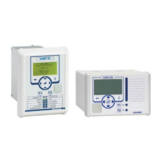
Voltage and frequency protection relay
Brand:
VAMP
| Category:
Relays
| Size: 3 MB
Table of Contents
Table of Contents
3
1 General
4
Relay Features
4
User Interface
5
Operating Safety
5
2 Local Panel User Interface
6
Relay Front Panel
6
Display
7
Menu Navigation and Pointers
8
Keypad
9
Operation Indicators
10
Adjusting Display Contrast
11
Local Panel Operations
11
Navigating in Menus
11
Menu Structure of Protection Functions
14
Setting Groups
18
Fault Logs
19
Operating Levels
20
Operating Measures
22
Control Functions
22
Measured Data
23
Reading Event Register
24
Forced Control (Force)
25
Configuration and Parameter Setting
26
Parameter Setting
27
Setting Range Limits
28
Disturbance Recorder Menu DR
28
Configuring Digital Inputs DI
29
Configuring Digital Outputs DO
29
Configuring Analogue Outputs AO (Option)
30
Protection Menu Prot
30
Configuration Menu CONF
31
Protocol Menu Bus
32
Single Line Diagram Editing
35
Blocking and Interlocking Configuration
35
3 VAMPSET PC Software
36
Table of Contents
37
1 Introduction
40
Main Features
40
Principles of Numerical Protection Techniques
41
2 Protection Functions
44
Maximum Number of Protection Stages in One Application
44
General Features of Protection Stages
44
List of Protection Functions
49
Overvoltage Protection U> (59)
50
Volts/Hertz Over-Excitation Protection U F > (24)
53
Undervoltage Protection U < (27P)
56
Undervoltage Protection U< (27)
60
Zero Sequence Voltage Protection U > (59N)
63
Overfrequency and Underfrequency Protection F>, F< (81H/81L)
66
Synchrocheck (25)
69
Circuit Breaker Failure Protection CBFP (50BF)
76
Programmable Stages (99)
78
3 Supporting Functions
82
Event Log
82
Disturbance Recorder
84
Voltage Sags and Swells
88
Voltage Interruptions
90
Voltage Transformer Supervision
92
System Clock and Synchronization
93
Self-Supervision
97
Diagnostics
97
4 Measurement Functions
99
Measurement Accuracy
99
Minimum and Maximum Values
100
Voltage Measurement Modes
100
Symmetric Components
101
Primary, Secondary and Per Unit Scaling
105
Voltage Scaling
105
Analogue Output (Option)
108
Ma Scaling Example
108
5 Control Functions
109
Output Relays
109
Digital Inputs
110
Virtual Inputs and Outputs
112
Function Keys / F1 & F2
113
Output Matrix
114
Blocking Matrix
115
Controllable Objects
116
Local/Remote Selection
118
Logic Functions
119
6 Communication
120
Communication Ports
120
Local Port (Front Panel)
121
Remote Port
123
Extension Port
124
Ethernet Port
125
Communication Protocols
126
PC Communication
126
Modbus TCP and Modbus RTU
127
Profibus DP
128
SPA-Bus
130
Iec 60870-5-103
131
Dnp 3.0
133
Iec 60870-5-101
134
External I/O (Modbus RTU Master)
135
Iec 61850
135
Ethernet/Ip
137
7 Application
139
Trip Circuit Supervision
139
Trip Circuit Supervision with One Digital Input
140
Trip Circuit Supervision with Two Digital Inputs
145
8 Connections
149
Rear Panel View
149
Auxiliary Voltage
151
Output Relays
151
Serial Communication Connection
151
Pin Assignments of Communication Options
152
Front Panel Connector
154
Optional Digital Input/Output Card
155
External Option Modules
158
External Input / Output Module
158
Connection Examples
164
9 Technical Data
167
Connections
167
Measuring Circuitry
167
Auxiliary Voltage
167
Digital Inputs
167
Trip Contacts
168
Alarm Contacts
168
Local Serial Communication Port
168
Remote Control Connection (Option)
168
Analogue Output Connection (Option)
169
Tests and Environmental Conditions
169
Disturbance Tests
169
Test Voltages
169
Mechanical Tests
169
Environmental Conditions
169
Casing
170
Package
170
Protection Stages
170
Voltage Protection
170
Frequency Protection
172
Synchrocheck Function
173
Circuit-Breaker Failure Protection
173
Digital Input / Output Card (Option)
174
Supporting Functions
174
Disturbance Recorder (DR)
174
Voltage Sag & Swell
175
Voltage Interruptions
175
10 Abbreviations and Symbols
176
11 Construction
178
12 Order Information
180
13 Revision History
182
14 Reference Information
183
Advertisement
Advertisement
Related Products
VAMP 50
VAMP 51
VAMP 52
VAMP VAMP 59
VAMP VAMP 140
VAMP VAMP 150
VAMP VAMP 130
VAMP VAMP 135
VAMP VAMP 220
VAMP VAMP 220R
VAMP Categories
Relays
Protection Device
Adapter
Measuring Instruments
Control Unit
More VAMP Manuals
Login
Sign In
OR
Sign in with Facebook
Sign in with Google
Upload manual
Upload from disk
Upload from URL