
Related Manuals for Westermo LRW-102 Series


Summary of Contents for Westermo LRW-102 Series
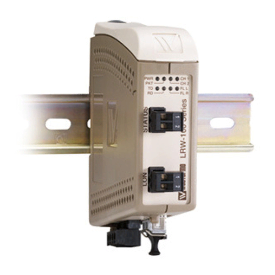
- Page 1 LRW-102 Series Fibre Optic industrial converter/repeater for LonWorks ® TP/FT-10 point-to-point, line and redundant ring...
- Page 2 6650-2260...
-
Page 3: General Information
Under no circumstances shall Westermo be responsible for any loss of data or income or any special, incidental, and consequential or indirect damages howsoever caused. -
Page 4: Before Installation
Do not use or store the unit in dusty, dirty areas, connectors as well as other mechanical part may be damaged. If the unit is not working properly, contact the place of purchase, nearest Westermo dis- tributor office or Westermo Tech support. -
Page 5: Maintenance
Note. Fibre Optic Handling Fibre optic equipment needs special treatment. It is very sensitive to dust and dirt. If the fibre will be disconnected from the modem the protective hood on the transmitter/ receiver must be connected. The protective hood must be kept on during transportation. The fibre optic cable must also be handle the same way. -
Page 6: Simplified Eu Declaration Of Conformity
Simplified EU declaration of conformity Hereby, Westermo declares that the equipment is in compliance with applicable EU directives. The full EU declaration of conformity and other detailed information are available at the respective product page at www.westermo.com. Agency approvals and standards compliance... -
Page 7: Type Tests And Environmental Conditions
Type tests and environmental conditions Electromagnetic Compatibility Phenomena Test Description Level EN 61000-4-2 Enclosure contact ± 4 kV Enclosure air ± 8 kV RF field AM modulated IEC 61000-4-3 Enclosure 10 V/m 80% AM (1 kHz), 80 – 1 000 MHz Fast transient EN 61000-4-4 Signal ports... - Page 8 Description The LRW-102 (LRW-102PP) offers an easy way to extend the distance between orks ® 78 kbit/s TP/FT network segments using a fibre optic link. The LRW-102PP is a fibre optic modem used for point-to-point applications and the LRW-102 is used for multidrop and redundant ring applications. It acts as a repeater between the two fibre optic links, and as a converter between fibre optical links and the LON TP/FT port.
-
Page 9: Functional Description
Functional description Converter TP/FT interface – optical fibre The LRW-102 (LRW-102PP) is a fibre optic converter that converts between TP/FT, and fibre optical link. ® orks Repeater – optical fibre links The LRW-102 is a fibre optic repeater that repeats received data from one fibre link out to the other link. - Page 10 Point-to-point communication via fibre optic network With only two network segments, the most cost effective solution is to use two point- to-point LRW-102PP units to create a single fibre optic connection. The point-to-point connection provides a totally transparent fibre link which means that all data received on one units TP/FT port will be forwarded unchanged to the other port, as illustrated in the figure.
-
Page 11: Normal Operation
Redundant ring communications via fibre optic network Under normal operation the L data is sent over ring A. Should a fault be ® orks detected on the fibre ring then the L data will be carried on rings A and B. ®... - Page 12 Behaviour under faulty condition Elapsed time from any kind of failure at the fibre optic network until data exchange after a corrective action depends on total length of fibre ring. This is typically 40–500 ms. During that time, the transferred data frames should be seen as corrupted or missed. Failure Indications Fibre interruption ring A, TX...
- Page 13 Bus or multidrop communications via fibre optic network CH 2 CH 1 CH 2 CH 1 CH 2 CH 1 CH 2 CH 1 Network Network Network Network The data is transferred via the fibre optic network to the serial ports of all units. If LRW-102 is connected to two optical fibre links (mid unit) converted data will be transmitted in both directions, via both CH 1 and CH 2.
-
Page 14: Status Interface
Status interface This interface enables supervision of fibre optic link state.<8 ohm means that status is OK. The fault state will be set if: … Local or remote fibre link errors exist. … The unit is out of service, e.g. no power supply. LON Channel delay The LON TP/FT-10 (EIA-709.3) specification states a maximum delay of 36 µs and a maximum of one repeater between any two nodes. - Page 15 Westermo has made tests with 60% load on the TP/FT-10 network and up to 60% load it is possible to increase the allowed delay to 127 µs.
-
Page 16: Interface Specifications
Interface specifications Power Rated voltage 12 to 48 VDC 24 VAC Operating voltage 10 to 60 VDC 20 to 30 VAC Rated current 400 mA @ 12 VDC 200 mA @ 24 VDC 100 mA @ 48 VDC Rated frequency AC: 48 to 62 Hz Inrush current I 0.2 A... - Page 17 Optical Power Budget The maximum supported link lengths as specified in the table above should only been seen as indicative. The allowed link length is calculated from the Optical Power Budget (OPB), (the available optical power for a fibre-optic link), and the attenuation of the fibre, comprising losses due to in-line connectors, splices, optical switches and a margin for link aging (typical 1.5 dB for 1300 nm).
- Page 18 Location of Interface ports, LED’s and DIP-switches LRW-102/ LRW-102PP LED Indicators(for details see page 17) Status Position Direction* Description Product marking In/Out Contact with posi- tion 2 when fibre optical links are in operation In/Out Common TP/FT -10 Position Direction* Description Product marking...
-
Page 19: Led Indicators
LED indicators Status Description In service (power) Power Flashing Fault condition Out of service – used – used CH 2 Fibre link at port CH 2 in operation. Data can be transmitted. (Not used in pp version) Fibre link at port CH 2 out of operation. (Not used in pp version) CH 1 Fibre link at port CH 1 in operation. -
Page 20: S1 Dip-Switch
Configuration All needed configurations and parameter settings are done by the DIP-switches, located under the top lid of the LRW-102 (LRW-102PP). DIP-switch settings Before DIP-switch settings: Prevent damage to internal electronics from electrostatic discharges (ESD) by discharging your body to a grounding point (e.g. use of wrist strap) Note: Disconnect power before DIP-switch settings. - Page 21 Mounting This unit should be mounted on 35 mm DIN-rail, which is horizontally mounted inside an apparatus cabinet, or similar. Snap on mounting, see figure. Cooling 10 mm * (0.4 inches) This unit uses convection cooling. To avoid obstructing the air- 25 mm flow around the unit, use the following spacing rules.
-
Page 22: Start-Up Guide
Start up guide Redundant ring application CH 2 CH 1 CH 2 CH 1 CH 2 CH 1 CH 2 CH 1 TX RX TX RX Network Network Network Network Ring A Ring B Follow the steps below to get the unit up and running in a simple application: …... - Page 23 Multidrop application CH 2 CH 1 CH 2 CH 1 CH 2 CH 1 CH 2 CH 1 Network Network Network Network Prepare the fibre optical network: … Multidrop, mid units (CH 1 & CH 2). Set switch S2:2 to ON. …...
-
Page 24: Point-To-Point Application
Point-to-point application CH 1 CH 1 TX RX Network Network Configure the network … Check that it is running correctly with the electrical serial network. Prepare the fibre optical network … Connect the fibre links between the units. … Connect the power supply to all units. …... - Page 25 Multidrop with Bi-di transceivers End unit 1 Unit 2 End unit 3 – Bi-di 1550 nm – Bi-di 1310 nm Bi-di 1310 nm Bi-di 1550 nm Point-to-point with Bi-di transceivers Unit 1 Unit 2 Bi-di 1310 nm Bi-di 1550 nm Note: With Bi-di fibre it is necessary to have one 1310 nm in one end and 1550 nm in the other end.
- Page 26 6650-2260...
- Page 27 6650-2260...
- Page 28 Westermo • SE-640 40 Stora Sundby, Sweden Tel +46 16 42 80 00 Fax +46 16 42 80 01 E-mail: info@westermo.com www.westermo.com REV. D 6650-2260 2018-11 Westermo Network Technologies AB, Sweden...
Need help?
Do you have a question about the LRW-102 Series and is the answer not in the manual?
Questions and answers