
Related Manuals for Westermo LRW-702-F2


Summary of Contents for Westermo LRW-702-F2
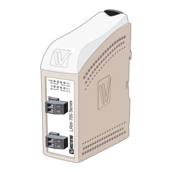
- Page 1 User Guide 6651-2271 LRW-702-F2 Fibre Optic industrial converter/repeater for LonWorks TP/FT-10 ® point-to-point, line and redundant ring www.westermo.com...
-
Page 2: Legal Information
Under no circumstances shall Westermo be responsible for any loss of data or income or any special, incidental, and consequential or indirect damages howsoever caused. -
Page 3: Before Installation
Do not use or store the unit in dusty, dirty areas, connectors as well as other mechanical part may be damaged. If the unit is not working properly, contact the place of purchase, nearest Westermo dis- tributor office or Westermo Tech support. -
Page 4: Maintenance
Note. Fibre Optic Handling Fibre optic equipment needs special treatment. It is very sensitive to dust and dirt. If the fibre will be disconnected from the modem the protective hood on the transmitter/ receiver must be connected. The protective hood must be kept on during transportation. The fibre optic cable must also be handle the same way. -
Page 5: Declaration Of Conformity
Declaration of Conformity Westermo Teleindustri AB Declaration of Conformity The manufacturer Westermo Teleindustri AB SE-640 40 Stora Sundby, Sweden Herewith declares that the product(s) Type of product Model Art no Industrial Converter/Router LRW-702-F2 3651-1401 is in conformity with the following EU directive(s). -
Page 6: Type Tests And Environmental Conditions
Power port to other 2 kVrms 50 Hz 1min isolated ports Environmental Temperature EN 60068-2-1 Operating –40 to +60ºC LRW-702-F2 EN 60068-2-2 Storage & Transport –40 to +70°C Humidity EN 60068-2-30 Operating 5 to 95% relative humidity Storage & Transport... -
Page 7: Functional Description
Repeater – optical fibre links The LRW-702-F2 is a fibre optic repeater that repeats received data from one fibre link out to the other link. This is useful e.g. for long distance communication, where electromagnetic interference may occur or when isolation of the electrical network is needed. -
Page 8: Interface Specifications
Interface specifications Power Rated voltage 12 to 48 VDC 24 VAC Operating voltage 10 to 60 VDC 20 to 30 VAC Rated current 400 mA @ 12 VDC 200 mA @ 24 VDC 100 mA @ 48 VDC Rated frequency AC: 48 to 62 Hz Inrush current I 0.2 A... - Page 9 Location of Interface ports, LEDs and DIP-switches LRW-702-F2 LED Indicators) Status Position Direction* Description Product marking In/Out Contact with posi- tion 2 when fibre optical links are in operation In/Out Common TP/FT-10 Position Direction* Description Product marking FX (Fibre) In/Out TP/FT-10 Ch 1 and Ch 2..
-
Page 10: Led Indicators
LED indicators Status Description Power is on. Power Power is off. Focal point Redundant ring member or multidrop unit. CH 2 Fiber link to other unit has been established at CH 2. Channel 2 link status Flashing Optical power detected but link to other unit has not been established at CH 2. -
Page 11: S1 Dip-Switch
Configuration All needed configurations and parameter settings are done by the DIP-switches, located under the top lid of the LRW-702-F2. DIP-switch settings Before DIP-switch settings: Prevent damage to internal electronics from electrostatic discharges (ESD) by discharging your body to a grounding point (e.g. use of wrist strap) Note: Disconnect power before DIP-switch settings. -
Page 12: Multidrop Configuration
Multidrop configuration Prepare the fibre optical network • The first and last LRW-702-F2 units must be configured as Multidrop end units by settting DIP-switch S2:2 to the ON position. (End units only have one fibre pair each and must know that this is a fact) •... - Page 13 Behavior during optical link failure If an optical fibre segment fails, all communication with units beyond the faulty fibre segment will be lost. To determine which fibre segment has failed, look at the FL L, CH 1 and CH 2 LEDs as show in the picture above. 6651-2271...
- Page 14 Redundant ring configuration Prepare the fibre optical network • One, and only one, of the LRW-702-F2 units must be configured as a ring focal point by setting DIP-switch S2:3 to the ON position. (The ring focal point acts as a logical end point in the optical fibre ring, thus forming a bus type of structure) •...
- Page 15 Behavior during optical link failure If an optical fibre segment fails, the LRW-702-F2 unit configured as focal point will reconfigure the system so that data is sent and received over the otherwise redundant fibre pair. To determine which fibre segment has failed, look at the FL L, CH 1 and CH 2 LEDs as show in the picture above.
- Page 16 702-F2 units. The following equation can be used to calculate the overall system delay: Maximum delay (µs) = Total fibre distance (m) / 200 + Number of LRW-702-F2 units For example, in a multidrop system comprising four LRW-702-F2 units connected together using three 1,5 km fibre links, the end to end delay will be: 3 x 1500 / 200 + 4 = 26,5 µs...
-
Page 17: Status Port
The LRW-702-F2 power supply is galvanically isolated from all other interfaces. Optical fibre interfaces LRW-702-F2 uses Small Form Factor Pluggable (SFP) transceivers. This means that a wide range of different fibre transceivers and connectors can be used. LONWORKS TP/FT-10 interface Connection terminal to a LONWORKS TP/FT-10 transceiver. - Page 18 Mounting This unit should be mounted on 35 mm DIN-rail, which is horizontally mounted inside an apparatus cabinet, or similar. Snap on mounting, see figure. Cooling 10 mm * (0.4 inches) This unit uses convection cooling. To avoid obstructing the air- 25 mm flow around the unit, use the following spacing rules.
- Page 19 Westermo • SE-640 40 Stora Sundby, Sweden Tel +46 16 42 80 00 Fax +46 16 42 80 01 E-mail: info@westermo.com www.westermo.com REV. A 6651-2271 2018-04 Westermo Teleindustri AB, Sweden...
Need help?
Do you have a question about the LRW-702-F2 and is the answer not in the manual?
Questions and answers