GORMAN-RUPP PUMPS PAH Series Installation, Operation, And Maintenance Manual With Parts List
Hide thumbs
Also See for PAH Series:

Subscribe to Our Youtube Channel
Related Manuals for GORMAN-RUPP PUMPS PAH Series


Summary of Contents for GORMAN-RUPP PUMPS PAH Series
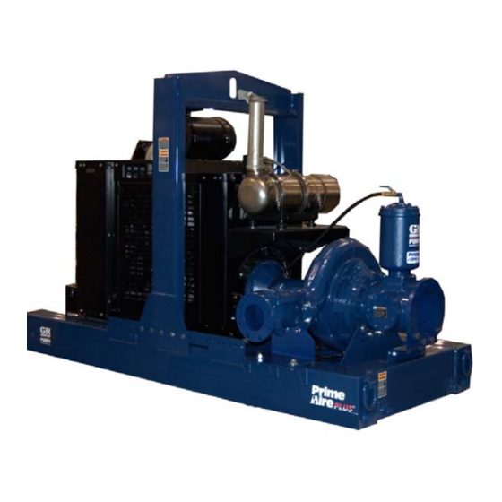
- Page 1 OM-06451-01 February 17, 2012 Rev. F 09‐15‐16 INSTALLATION, OPERATION, AND MAINTENANCE MANUAL WITH PARTS LIST PAH SERIESr PUMP MODEL PAH6B60-6068H GORMAN‐RUPP PUMPS www.grpumps.com 2012 Gorman‐Rupp Pumps Printed in U.S.A.
- Page 2 Register your new Gorman‐Rupp pump online at www.grpumps.com Valid serial number and e‐mail address required. The engine exhaust from this product contains chemicals known to the State of California to cause cancer, birth defects or other reproductive harm. RECORD YOUR PUMP MODEL AND SERIAL NUMBER Please record your pump model and serial number in the spaces provided below.
-
Page 3: Table Of Contents
TABLE OF CONTENTS INTRODUCTION ..........PAGE I - 1 SAFETY ‐... - Page 4 TABLE OF CONTENTS (continued) STOPPING ..............PAGE C - 4 Manual Stopping .
-
Page 5: Introduction
PAH SERIES OM-06451 INTRODUCTION Thank You for purchasing a Gorman‐Rupp pump. HAZARD AND INSTRUCTION Read this manual carefully to learn how to safely DEFINITIONS install and operate your pump. Failure to do so could result in personal injury or damage to the The following are used to alert maintenance per... -
Page 6: Safety - Section A
PAH SERIES OM-06451 SAFETY ‐ SECTION A This information applies to Prime Aire forming any maintenance. Failure to do Series engine driven pumps. Refer to so may result in serious personal injury. the manual accompanying the engine before attempting to begin operation. - Page 7 OM-06451 PAH SERIES hose connections are tight, properly fingers or tools, causing severe injury to supported and secure before operation. personnel. Make sure the pump is level. Lower jack Do not operate the pump against a stands and chock the wheels, if so closed discharge valve.
-
Page 8: Installation - Section B
PAH SERIES OM-06451 INSTALLATION - SECTION B Review all SAFETY information in Section A. configuration, and priming must be tailored to the specific application. Since the pressure supplied Since pump installations are seldom identical, this to the pump is critical to performance and safety,... -
Page 9: Battery Installation
OM-06451 PAH SERIES c. Carefully read all tags, decals, and markings POSITIONING PUMP on the pump assembly, and perform all duties indicated. Note that the pump shaft rotates in the required direction. Death or serious personal injury and damage to the pump or components can occur if proper lifting procedures Only operate this pump in the direction in... -
Page 10: Suction And Discharge Piping
PAH SERIES OM-06451 to secure them when filled with liquid and under pressure. Gauges If the pump has been mounted on a mov able base, do not attempt to operate the The pump is drilled and tapped for installing dis... -
Page 11: Sealing
OM-06451 PAH SERIES Sealing air to escape from the liquid before it is drawn into the suction inlet. Since even a slight leak will affect priming, head, If two suction lines are installed in a single sump, and capacity, especially when operating with a... -
Page 12: Discharge Lines
PAH SERIES OM-06451 Figure 2. Recommended Minimum Suction Line Submergence vs. Velocity DISCHARGE LINES Siphoning If the application involves a high discharge head, gradually close the discharge Do not terminate the discharge line at a level lower than that of the liquid being pumped unless a si... -
Page 13: Float Switch Installation
OM-06451 PAH SERIES Float Switch Installation pipe is available, attach the float switch cable to the standpipe in the sump at the approxi The Float Switch autostart system employs either a mate desired liquid level. single or double float switch, where a bulb raises or lowers (floats) with the liquid level, thus activating b. -
Page 14: Operation - Section C
OM-06451 PAH SERIES OPERATION - SECTION C Review all SAFETY information in Section A. cated (see LUBRICATION in MAINTENANCE AND REPAIR). Follow the instructions on all tags, labels and The pump will begin to prime upon startup. The air decals attached to the pump. -
Page 15: Automatic Starting
OM-06451 PAH SERIES box to the “MANUAL ” position, then press and hold If full priming is not achieved, the discharge check the “ENTER” button until the engine starts. valve may be malfunctioning. If this occurs, shut down the pump and consult the separate Mainte... -
Page 16: Operational Checks
OM-06451 PAH SERIES Allow an over‐heated pump to com This pump is equipped with automatic pletely cool before servicing. Do not re liquid level controls, and is subject to move plates, covers, gauges, or fittings automatic restart. Keep hands and from an overheated pump. - Page 17 OM-06451 PAH SERIES After stopping the pump, switch off the engine igni the unit and/or injury to personnel. Safe tion and remove the key to ensure that the pump ty shutdown features are pre‐set at the will remain inoperative. factory; do not attempt to adjust any of the settings.
- Page 18 OM-06451 PAH SERIES conditions, change the filter more frequently. Irreg Consult the manual accompanying the air com ular performance and loss of power usually indi pressor and preform all duties and checks as indi cate a dirty fuel filter. cated.
- Page 19 OM-06451 PAH SERIES TROUBLESHOOTING - SECTION D Review all SAFETY information in Section A. 5. Close the suction and discharge valves. 6. Vent the pump slowly and cau tiously. 7. Drain the pump. Before attempting to open or service the pump: 1.
- Page 20 OM-06451 PAH SERIES TROUBLE POSSIBLE CAUSE PROBABLE REMEDY Check strainer and clean if neces Strainer clogged. PUMP STOPS OR FAILS TO DELIVER sary. RATED FLOW OR Check and clean check valve. Discharge check valve clogged. PRESSURE (cont.) Suction intake not submerged at Check installation and correct proper level or sump too small.
- Page 21 OM-06451 PAH SERIES TROUBLE POSSIBLE CAUSE PROBABLE REMEDY BEARINGS RUN Bearing temperature is high, but Check bearing temperature regu TOO HOT within limits. larly to monitor any increase. Low or incorrect lubricant. Check for proper type and level of lubricant.
- Page 22 OM-06451 PAH SERIES Preventive Maintenance Schedule Service Interval* Item Daily Weekly Monthly Semi‐ Annually Annually General Condition (Temperature, Unusual Noises or Vibrations, Cracks, Leaks, Loose Hardware, Etc.) Pump Performance (Gauges, Speed, Flow) Bearing Lubrication Seal Lubrication (And Packing Adjustment, If So Equipped) V‐Belts (If So Equipped)
- Page 23 OM-06451 PAH SERIES PUMP MAINTENANCE AND REPAIR - SECTION E MAINTENANCE AND REPAIR OF THE WEARING PARTS OF THE PUMP WILL MAINTAIN PEAK OPERATING PERFORMANCE. STANDARD PERFORMANCE FOR PUMP MODEL PAH6B60-6068H Based on 70 F (21 C) clear water at sea level Contact the Gorman‐Rupp Company to verify per...
- Page 24 OM-06451 PAH SERIES PARTS PAGE ILLUSTRATION Figure 1. Pump Model PAH6B60-6068H PAGE E - 2 MAINTENANCE & REPAIR...
- Page 25 OM-06451 PAH SERIES Pump Model PAH6B60-6068H PARTS LIST (From S/N 1507875 Up) ITEM PART MAT'L PART NAME NUMBER CODE JOHN DEERE POWER UNIT 46143-070 PUMP END ASSEMBLY 46133-293 PUMP MOUNTING KIT 48157-019 BATTERY SEE OPTIONS NOT SHOWN: G‐R DECAL GR-06...
- Page 26 OM-06451 PAH SERIES ILLUSTRATION Figure 2. 46143-070 Power Unit Kit PAGE E - 4 MAINTENANCE & REPAIR...
- Page 27 OM-06451 PAH SERIES PARTS LIST 46143-070 Power Unit Kit ITEM PART NAME PART MAT'L ITEM PART NAME PART MAT'L NUMBER CODE NUMBER CODE BASE/FUEL TANK ASSY 41553-008 24150 RED. CPLG AE1608 15079 LIFTING BAIL KIT 48274-805 --- 1/2" CHECK VALVE 26641-092 --- J.D.
- Page 28 OM-06451 PAH SERIES ILLUSTRATION Figure 3. 46133-293 Pump End Assembly PAGE E - 6 MAINTENANCE & REPAIR...
- Page 29 OM-06451 PAH SERIES 46133-293 Pump End Assembly PARTS LIST ITEM PART MAT'L PART NAME NUMBER CODE 66J60-(SAE 3/11.5) 46133-292 PRIMING CHAMBER KIT 48275-005 STUD C1414 15991 GASKET 25113-040 LOCK WASHER 15991 HEX NUT 15991 SUCTION SPOOL 38644-807 10000 GASKET 25113-034...
- Page 30 OM-06451 PAH SERIES ILLUSTRATION Figure 4. 46133-292 Pump End Assembly PAGE E - 8 MAINTENANCE & REPAIR...
- Page 31 OM-06451 PAH SERIES PARTS LIST 46133-292 Pump End Assembly ITEM PART MAT'L PART NAME NUMBER CODE PUMP CASING SEE NOTE BELOW SUCTION HEAD 38246-614 10000 O‐RING 25152-387 O‐RING 25152-387 PIPE PLUG 15079 PIPE PLUG 15079 REPAIR ROTATING ASSY 44163-510 STUD...
- Page 32 OM-06451 PAH SERIES ILLUSTRATION Figure 5. 44163-510 Repair Rotating Assembly PAGE E - 10 MAINTENANCE & REPAIR...
- Page 33 OM-06451 PAH SERIES PARTS LIST 44163-510 Repair Rotating Assembly ITEM PART MAT'L PART NAME NUMBER CODE IMPELLER 38621-738 11010 SOCKET HEAD CAP SCREW BD1206 15991 IMPELLER WASHER 31167-042 17000 " SOCKET HEAD CAP SCREW BD1006 15991 " IMPELLER WASHER 31167-096...
- Page 34 OM-06451 PAH SERIES ILLUSTRATION Figure 6. 48275-005 Priming Chamber Kit ITEM PART MAT'L PART NAME NUMBER CODE PRIMING CHAMBER ASSY 46112-709 PIPE BUSHING AP1608 11999 STREET ELBOW RS08 11999 BALL VALVE 26631-052 STUD C0809 15991 HEX NUT 15991 LOCK WASHER...
- Page 35 OM-06451 PAH SERIES ILLUSTRATION Figure 7. 46112-709 Priming Chamber Assembly PARTS LIST ITEM PART MAT'L PART NAME NUMBER CODE PRIMING VALVE 26664-007 -ORIFICE BUTTON 26688-021 HEX HD CAPSCREW B0806 15991 LOCKWASHER 15991 PRIMING VALVE GASKET 38683-657 19060 PRIMING CHAMBER 38343-020...
- Page 36 OM-06451 PAH SERIES ILLUSTRATION Figure 8. 44162-162 Drive Assembly ITEM PART MAT'L PART NAME NUMBER CODE COUPLING KIT 48112-006 -BUSHING 24131-492 -COUPLING ASSEMBLY 24391-106 LOCKWASHER 21171-536 SOCKET HEAD CAPSCREW B0612 15991 SOCKET HEAD CAPSCREW 22645-174 HEX HEAD CAPSCREW B0606 15991...
- Page 37 OM-06451 PAH SERIES PUMP AND SEAL DISASSEMBLY lishing that neither personal safety nor pump integrity are compromised by AND REASSEMBLY such practices. Review all SAFETY information in Section A. Follow the instructions on all tags, label and de cals attached to the pump.
- Page 38 OM-06451 PAH SERIES Support the discharge check valve assembly (12) approved by Gorman‐Rupp. Use of non‐ using a sling and a suitable lifting device. Remove authorized parts may result in damage to the hardware (not shown) and separate the dis...
- Page 39 OM-06451 PAH SERIES Remove and discard the pump casing O‐ring (3A). Seal Removal (Figures 5 and 9) Draining Oil From Seal Cavity Remove the spring centering washer and seal spring. Slide the shaft sleeve (7) and rotating por (Figure 5) tion of the seal off the shaft as a unit.
- Page 40 OM-06451 PAH SERIES Move the pump end to a clean, well equipped shop soaked in cleaning solvent. Inspect the parts for area for further disassembly. wear or damage and replace as necessary. Shaft and Bearing Removal and Disassembly (Figure 5) Most cleaning solvents are toxic and When the pump is properly operated and main...
- Page 41 OM-06451 PAH SERIES Clean and inspect the bearings as indicated in Shaft And Bearing Removal And Disassembly. When installing the bearings onto the shaft, never press or hit against the outer race, balls, rollers or cage. Press only on To prevent damage during removal from the inner race.
- Page 42 OM-06451 PAH SERIES Apply a light coating of oil to the lip of the outboard parts may not fully engage, or a pre‐load oil seal (11) and press it into the pedestal with the condition can cause premature bearing lip positioned as shown in Figure 5. The face of the failure.
- Page 43 OM-06451 PAH SERIES sparks, and flame. Read and follow all A new seal assembly should be installed precautions printed on solvent contain any time the old seal is removed from the ers. pump. Wear patterns on the finished faces cannot be realigned during reassembly.
- Page 44 OM-06451 PAH SERIES Slide the rotating subassembly (consisting of the hardware to fully seat the pump casing against the rotating element, retainer and bellows) onto the seal plate (9, Figure 5). sleeve until the rotating element is just flush with Suction Head and Wear Ring Installation and the chamfered end of the sleeve.
- Page 45 OM-06451 PAH SERIES (14 and 15). Install the two remaining back cover bracket and reinstall the pivot pin. Secure the pivot nuts snugly against the adjusting screws. pin with the previously removed “e‐clip”. Adjust the orifice button seating as necessary by...
- Page 46 OM-06451 PAH SERIES bearings to over‐heat, resulting in premature bear ing failure. Monitor the condition of the bearing lubri NOTE cant regularly for evidence of rust or mois ture condensation. This is especially im The white reflector in the sight gauge must be posi...
- Page 47 For Warranty Information, Please Visit www.grpumps.com/warranty or call: U.S.: 419-755-1280 Canada: 519-631-2870 International: +1-419-755-1352 GORMAN‐RUPP PUMPS...
Need help?
Do you have a question about the PAH Series and is the answer not in the manual?
Questions and answers