
Related Manuals for GORMAN-RUPP PUMPS PAH8A60-6090H


Summary of Contents for GORMAN-RUPP PUMPS PAH8A60-6090H
- Page 1 OM-06453-04 August 01, 2017 INSTALLATION, OPERATION, AND MAINTENANCE MANUAL WITH PARTS LIST PAH SERIESr PUMP MODEL PAH8A60-6090H GORMAN‐RUPP PUMPS www.grpumps.com 2017 Gorman‐Rupp Pumps Printed in U.S.A.
- Page 2 Register your new Gorman‐Rupp pump online at www.grpumps.com Valid serial number and e‐mail address required. The engine exhaust from this product contains chemicals known to the State of California to cause cancer, birth defects or other reproductive harm. RECORD YOUR PUMP MODEL AND SERIAL NUMBER Please record your pump model and serial number in the spaces provided below.
-
Page 3: Table Of Contents
TABLE OF CONTENTS INTRODUCTION ..........PAGE I - 1 SAFETY ‐... - Page 4 TABLE OF CONTENTS (continued) Safety Shutdown System ..........PAGE C - 3 PERIODIC CHECKS .
-
Page 5: Introduction
PAH SERIES OM-06453 INTRODUCTION Thank You for purchasing a Gorman‐Rupp pump. HAZARD AND INSTRUCTION Read this manual carefully to learn how to safely DEFINITIONS install and operate your pump. Failure to do so could result in personal injury or damage to the The following are used to alert maintenance per... -
Page 6: Safety - Section A
PAH SERIES OM-06453 SAFETY ‐ SECTION A This information applies to Prime Aire the positive battery cable before per Series pumps. Refer to the manual ac forming any maintenance. Failure to do companying the engine or power so may result in serious personal injury. source before attempting to begin oper... - Page 7 OM-06453 PAH SERIES certain that the pump and all piping or fingers or tools, causing severe injury to hose connections are tight, properly personnel. supported and secure before operation. Make sure the pump is level. Lower jack stands and chock the wheels, if so Do not operate the pump against a equipped.
-
Page 8: Installation - Section B
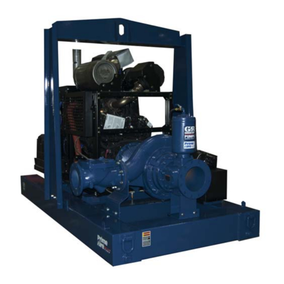
See Figure 1 for the approximate physical dimen some of the information such as mounting, line sions of this pump. OUTLINE DRAWING Figure 1. Pump Model PAH8A60-6090H PREINSTALLATION INSPECTION a. Inspect the pump for cracks, dents, damaged threads, and other obvious damage. -
Page 9: Battery Installation
OM-06453 PAH SERIES c. Carefully read all tags, decals, and markings POSITIONING PUMP on the pump assembly, and perform all duties indicated. Note that the pump shaft rotates in the required direction. Death or serious personal injury and damage to the pump or components can occur if proper lifting procedures are not observed. -
Page 10: Suction And Discharge Piping
PAH SERIES OM-06453 Connections to Pump including the bearings, shaft and/or bear ing housing may occur if the pump is oper Before tightening a connecting flange, align it ex ated for an extended period of time on an actly with the pump port. Never pull a pipe line into unlevel surface. -
Page 11: Sealing
OM-06453 PAH SERIES If a strainer not furnished with the pump is installed If it is necessary to position inflow close to the suc by the pump user, make certain that the total area tion inlet, install a baffle between the inflow and the of the openings in the strainer is at least three or suction inlet at a distance 1‐1/2 times the diameter four times the cross section of the suction line, and... -
Page 12: Discharge Lines
PAH SERIES OM-06453 Figure 2. Recommended Minimum Suction Line Submergence vs. Velocity DISCHARGE LINES Siphoning If the application involves a high discharge head, gradually close the discharge Do not terminate the discharge line at a level lower than that of the liquid being pumped unless a si throttling valve before stopping the pump. -
Page 13: Float Switch Installation
OM-06453 PAH SERIES Float Switch Installation pipe is available, attach the float switch cable to the standpipe in the sump at the approxi mate desired liquid level. The Float Switch autostart system employs either a single or double float switch, where a bulb raises or lowers (floats) with the liquid level, thus activating b. - Page 14 PAH SERIES OM-06453 that the liquid in the priming chamber never fully Next, install a drain line between the pump drain freezes. and the wet well or sump. This line must remain submerged in the liquid below the pump down lev The second method involves configuring the el of the liquid level control device;...
-
Page 15: Operation - Section C
OM-06453 PAH SERIES OPERATION - SECTION C OPERATION Make sure the pump is level. Lower the jack stands and chock the wheels, if so equipped. Review all SAFETY information in Section A. Follow the instructions on all tags, labels and decals attached to the pump. -
Page 16: Operation In Extreme Heat
OM-06453 PAH SERIES and system operating pressure. Do not operate Leakage below the recommended operating speed (if appli cable). Once the pump is fully primed, no leakage should be visible at pump mating surfaces, or at pump connections or fittings. Keep all line connections and fittings tight to maintain maximum pump effi... -
Page 17: Strainer Check
OM-06453 PAH SERIES Strainer Check Should any of the safety features cause the engine to shut down, the cause must be determined and corrected before putting the unit back into service. Check the strainer regularly, and clean it as neces sary. - Page 18 OM-06453 PAH SERIES tenance and Repair). Bearing overheating can COLD WEATHER PRESERVATION also be caused by shaft misalignment and/or ex cessive vibration. If the pump will be idle for an extended period of When pumps are first started, the bearings may time in below freezing conditions, drain the pump seem to run at temperatures above normal.
- Page 19 OM-06453 PAH SERIES TROUBLESHOOTING - SECTION D Review all SAFETY information in Section A. 5. Close the suction and discharge valves. 6. Vent the pump slowly and cau tiously. 7. Drain the pump. Before attempting to open or service the pump: 1.
- Page 20 OM-06453 PAH SERIES TROUBLE POSSIBLE CAUSE PROBABLE REMEDY Check strainer and clean if neces Strainer clogged. PUMP STOPS OR FAILS TO DELIVER sary. RATED FLOW OR Check and clean check valve. Discharge check valve clogged. PRESSURE (cont.) Suction intake not submerged at Check installation and correct proper level or sump too small.
- Page 21 OM-06453 PAH SERIES TROUBLE POSSIBLE CAUSE PROBABLE REMEDY BEARINGS RUN Bearing temperature is high, but Check bearing temperature regu TOO HOT within limits. larly to monitor any increase. Low or incorrect lubricant. Check for proper type and level of lubricant. Suction and discharge lines not prop...
- Page 22 OM-06453 PAH SERIES Preventive Maintenance Schedule Service Interval* Item Daily Weekly Monthly Semi‐ Annually Annually General Condition (Temperature, Unusual Noises or Vibrations, Cracks, Leaks, Loose Hardware, Etc.) Pump Performance (Gauges, Speed, Flow) Bearing Lubrication Seal Lubrication (And Packing Adjustment, If So Equipped) V‐Belts (If So Equipped) Air Release Valve Plunger Rod (If So Equipped) Front Impeller Clearance (Wear Plate)
- Page 23 PAH SERIES PUMP MAINTENANCE AND REPAIR - SECTION E MAINTENANCE AND REPAIR OF THE WEARING PARTS OF THE PUMP WILL MAINTAIN PEAK OPERATING PERFORMANCE. STANDARD PERFORMANCE FOR PUMP MODEL PAH8A60-6090H Based on 70 F (21 C) clear water at sea level Contact the Gorman‐Rupp Company to verify per...
- Page 24 OM-06453 PA SERIES PARTS PAGE ILLUSTRATION Figure 1. Pump Model PAH8A60-6090H PAGE E - 2 MAINTENANCE & REPAIR...
- Page 25 OM-06453 PAH SERIES Pump Model PAH8A60-6090H PARTS LIST (From S/N 1642852 Up) ITEM PART PART NAME NUMBER PUMP END ASSEMBLY 46183-145 6090H POWER UNIT 46143-152 PUMP MOUNTING KIT 48157-095 BATTERY SEE OPTIONS NOT SHOWN: G‐R DECAL GR-06 PRIME AIRE PLUS DECAL...
- Page 26 OM-06453 PA SERIES ILLUSTRATION Figure 2. John Deere Power Unit PAGE E - 4 MAINTENANCE & REPAIR...
- Page 27 OM-06453 PAH SERIES PARTS LIST John Deere Power Unit ITEM PART NAME PART ITEM PART NAME PART NUMBER NUMBER JD 6090H TIER 3 ENGINE 29224-363 HOSE BARB FITTING 26523-061 LIFTING BAIL KIT 48274-808 PIPE NIPPLE T0822 15079 CNTRL PANEL INSTALL KIT48122-544 2/O CABLE SUB ASS'Y 47311-214 BATTERY BOX ASSY...
- Page 28 OM-06453 PA SERIES ILLUSTRATION Figure 3. John Deere Power Unit (Cont'd) PAGE E - 6 MAINTENANCE & REPAIR...
- Page 29 OM-06453 PAH SERIES PARTS LIST John Deere Power Unit (Cont'd) ITEM PART NAME PART ITEM PART NAME PART NUMBER NUMBER JD 6090H TIER 3 ENGINE 29224-363 HOSE BARB FITTING 26523-061 LIFTING BAIL KIT 48274-808 PIPE NIPPLE T0822 15079 CNTRL PANEL INSTALL KIT48122-544 2/O CABLE SUB ASS'Y 47311-214 BATTERY BOX ASSY...
- Page 30 OM-06453 PA SERIES ILLUSTRATION Figure 4. Pump End Assembly PAGE E - 8 MAINTENANCE & REPAIR...
- Page 31 OM-06453 PAH SERIES Pump End Assembly PARTS LIST ITEM PART PART NAME NUMBER REPAIR ROTATING ASSEMBLY 44163-654 HEX NUT D12 15991 LOCK WASHER J12 15991 O‐RING 25152-387 STUD C1211 15991 PIPE PLUG P12 15079 PUMP CASING 38218-306 11010 PRIMING CHAMBER KIT 48275-005 G‐R DECAL 6 IN GR-06...
- Page 32 OM-06453 PA SERIES ILLUSTRATION Figure 5. Repair Rotating Assembly PAGE E - 10 MAINTENANCE & REPAIR...
- Page 33 OM-06453 PAH SERIES PARTS LIST Repair Rotating Assembly ITEM PART PART NAME NUMBER SOCKET HEAD CAP SCREW DM1206 15991 WASHER NORD-LOCK 3/4" 21177-224 IMPELLER WASHER 31167-042 17000 ROLL PIN S2197 IMPELLER 38621-734 11010 SHIM SET 48261-033 MECH SEAL 25285-822 SHAFT SLEEVE 31163-022 17000 O‐RING 25152-150...
- Page 34 OM-06453 PA SERIES ILLUSTRATION Figure 6. Priming Chamber Kit ITEM PART PART NAME NUMBER PRIMING CHAMBER ASSY 46112-709 PIPE BUSHING AP1608 15070 STREET ELBOW RS08 11999 BALL VALVE 26631-052 STUD C0809 15991 HEX NUT D08 15991 LOCK WASHER J08 15991 GASKET 38687-053 19060 BAFFLE...
- Page 35 OM-06453 PAH SERIES ILLUSTRATION Figure 7. Priming Chamber Assembly PARTS LIST ITEM PART PART NAME NUMBER PRIMING VALVE 26664-007 -ORIFICE BUTTON 26688-021 HEX HD CAPSCREW B0806 15991 LOCKWASHER J08 15991 PRIMING VALVE GASKET 38683-657 19060 PRIMING CHAMBER 38343-020 10000 STRAINER ASSY 46641-222 17000 INDICATES PARTS RECOMMENDED FOR STOCK MAINTENANCE &...
- Page 36 OM-06453 PA SERIES ILLUSTRATION Figure 8. Drive Assembly ITEM PART PART NAME NUMBER COUPLING KIT 48112-017 -BUSHING, 3020 x 2.50 24131-433 -COUPLING ASSEMBLY, 80 DURO 24391-109 -LOCK WASHER 21171-905 -SOCKET HEAD CAP SCREW BD0810 15990 -SOCKET HEAD CAP SCREW 22644-226 HEX HEAD CAP SCREW B0706 15991 HEX HEAD CAP SCREW...
- Page 37 OM-06453 PAH SERIES PUMP AND SEAL DISASSEMBLY pump integrity are compromised by such practices. AND REASSEMBLY Review all SAFETY information in Section A. Follow the instructions on all tags, label and de cals attached to the pump. Before attempting to open or service the pump: This pump requires little service due to its rugged, 1.
- Page 38 OM-06453 PAH SERIES charge check valve assembly and gasket (not authorized parts may result in damage to shown) from the pump assembly (7). the equipment and/or injury to personnel and will invalidate the warranty. The flapper and cover O‐ring are the only service able parts of the check valve.
- Page 39 OM-06453 PAH SERIES vent the oil in the seal cavity from escaping as the Use a pair of stiff wires with hooked ends to remove impeller is removed. the stationary element from the seal plate bore. An alternate method of removing the stationary Position a clean container under the seal cavity seal components is to remove the hardware (14 drain plug (18).
- Page 40 OM-06453 PAH SERIES Clean the bearings thoroughly in fresh cleaning is not recommended. These operations solvent. Dry the bearings with filtered compressed should be performed only in a properly air and coat with light oil. equipped shop by qualified personnel. NOTE There are no provisions for draining the lubricant from the pedestal.
- Page 41 OM-06453 PAH SERIES The bearings may be heated to ease installation. Slide the shaft and assembled bearings into the An induction heater, hot oil bath, electric oven, or pedestal until the inboard bearing is fully seated hot plate may be used to heat the bearings. Bear against the bearing retaining ring.
- Page 42 OM-06453 PAH SERIES Apply a light coating of oil to the lip of the oil seal The end of the shaft must be extend 1.10 (31) and press it into the drive flange (30) with the inches (27.9 mm) from the face of the lip positioned as shown in Figure 5.
- Page 43 OM-06453 PAH SERIES Clean the seal cavity and shaft with a cloth soaked any time the old seal is removed from the in fresh cleaning solvent. Inspect the stationary pump. Wear patterns on the finished faces seat bore in the seal plate for dirt, nicks and burrs, cannot be realigned during reassembly.
- Page 44 OM-06453 PAH SERIES water. Do not use oil or any substitute lubricant casing over the rotating assembly. Install the hard other than water. ware (2 and 3) on the studs (5) and use the hard ware to fully seat the pump casing against the seal Slide the rotating subassembly (consisting of the plate (10, Figure 5).
- Page 45 OM-06453 PAH SERIES Adjust the orifice button seating as necessary by install the vented plug. Check the oil level regularly screwing the orifice button into or out of the linkage and maintain it at the middle of the sight gauge. bar.
- Page 46 For Warranty Information, Please Visit www.grpumps.com/warranty or call: U.S.: 419-755-1280 Canada: 519-631-2870 International: +1-419-755-1352 GORMAN‐RUPP PUMPS...
Need help?
Do you have a question about the PAH8A60-6090H and is the answer not in the manual?
Questions and answers