GORMAN-RUPP PUMPS PAH SERIES Installation, Operation And Maintenance Manual
Hide thumbs
Also See for PAH SERIES:

Related Manuals for GORMAN-RUPP PUMPS PAH SERIES


Summary of Contents for GORMAN-RUPP PUMPS PAH SERIES
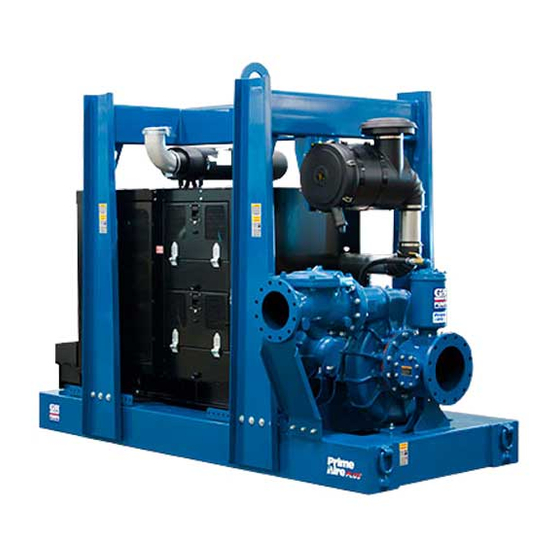
- Page 1 OM-06651-02 July 11, 2016 Rev. A - 9/3/19 INSTALLATION, OPERATION, AND MAINTENANCE MANUAL WITH PARTS LIST PAH SERIESr PUMP MODEL PAH10B60-6135H GORMAN‐RUPP PUMPS www.grpumps.com 2016 Gorman‐Rupp Pumps Printed in U.S.A.
- Page 2 Register your new Gorman‐Rupp pump online at www.grpumps.com Valid serial number and e‐mail address required. The engine exhaust from this product contains chemicals known to the State of California to cause cancer, birth defects or other reproductive harm. RECORD YOUR PUMP MODEL AND SERIAL NUMBER Please record your pump model and serial number in the spaces provided below.
-
Page 3: Table Of Contents
TABLE OF CONTENTS INTRODUCTION ..........PAGE I - 1 SAFETY ‐... - Page 4 TABLE OF CONTENTS (continued) Engine Fuel Filter ............PAGE C - 3 Engine Oil .
-
Page 5: Introduction
PAH SERIES OM-06651 INTRODUCTION Thank You for purchasing a Gorman‐Rupp pump. HAZARD AND INSTRUCTION Read this manual carefully to learn how to safely DEFINITIONS install and operate your pump. Failure to do so could result in personal injury or damage to the The following are used to alert maintenance per... -
Page 6: Safety - Section A
PAH SERIES OM-06651 SAFETY ‐ SECTION A This information applies to Prime Aire forming any maintenance. Failure to do Series engine driven pumps. Refer to so may result in serious personal injury. the manual accompanying the engine before attempting to begin operation. - Page 7 OM-06651 PAH SERIES hose connections are tight, properly fingers or tools, causing severe injury to supported and secure before operation. personnel. Make sure the pump is level. Lower jack Do not operate the pump against a stands and chock the wheels, if so closed discharge valve.
-
Page 8: Installation - Section B
PAH SERIES OM-06651 INSTALLATION - SECTION B Review all SAFETY information in Section A. configuration, and priming must be tailored to the specific application. Since the pressure supplied Since pump installations are seldom identical, this to the pump is critical to performance and safety,... -
Page 9: Battery Installation
OM-06651 PAH SERIES c. Carefully read all tags, decals, and markings POSITIONING PUMP on the pump assembly, and perform all duties indicated. Note that the pump shaft rotates in the required direction. Death or serious personal injury and damage to the pump or components can occur if proper lifting procedures are not observed. -
Page 10: Suction And Discharge Piping
PAH SERIES OM-06651 Connections to Pump including the bearings, shaft and/or bear ing housing may occur if the pump is oper Before tightening a connecting flange, align it ex ated for an extended period of time on an actly with the pump port. Never pull a pipe line into unlevel surface. -
Page 11: Sealing
OM-06651 PAH SERIES If a strainer not furnished with the pump is installed If it is necessary to position inflow close to the suc by the pump user, make certain that the total area tion inlet, install a baffle between the inflow and the of the openings in the strainer is at least three or suction inlet at a distance 1‐1/2 times the diameter... -
Page 12: Discharge Lines
PAH SERIES OM-06651 Figure 2. Recommended Minimum Suction Line Submergence vs. Velocity DISCHARGE LINES Siphoning If the application involves a high discharge head, gradually close the discharge Do not terminate the discharge line at a level lower than that of the liquid being pumped unless a si... -
Page 13: Float Switch Installation
OM-06651 PAH SERIES Float Switch Installation pipe is available, attach the float switch cable to the standpipe in the sump at the approxi mate desired liquid level. The Float Switch autostart system employs either a single or double float switch, where a bulb raises or lowers (floats) with the liquid level, thus activating b. - Page 14 PAH SERIES OM-06651 that the liquid in the priming chamber never fully Next, install a drain line between the pump drain freezes. and the wet well or sump. This line must remain submerged in the liquid below the pump down lev...
-
Page 15: Operation - Section C
OM-06651 PAH SERIES OPERATION - SECTION C OPERATION Make sure the pump is level. Lower the jack stands and chock the wheels, if so equipped. Review all SAFETY information in Section A. Follow the instructions on all tags, labels and decals attached to the pump. -
Page 16: Operation In Extreme Heat
OM-06651 PAH SERIES and system operating pressure. Do not operate the source of the leak, check the point of installa below the recommended operating speed (if appli tion of the vacuum gauge. cable). Liquid Temperature And Overheating The maximum liquid temperature for this pump is F (71 C). -
Page 17: Stopping
OM-06651 PAH SERIES STOPPING shutdown before putting the unit back into service. Consult the factory for ad ditional information. Manual Stopping PERIODIC CHECKS In the manual mode, reduce the throttle speed slowly, and allow the engine to idle briefly before Seal Cavity And Bearing Lubrication turning the keyswitch to `OFF'. - Page 18 OM-06651 PAH SERIES Consult the manual accompanying the engine, been pumping liquids containing a large amount of and change the oil filter periodically as indicated. If solids, drain the pump, and flush it thoroughly with operated under extremely dusty conditions, clean water.
- Page 19 OM-06651 PAH SERIES TROUBLESHOOTING - SECTION D Review all SAFETY information in Section A. 5. Close the suction and discharge valves. 6. Vent the pump slowly and cau tiously. 7. Drain the pump. Before attempting to open or service the pump: 1.
- Page 20 OM-06651 PAH SERIES TROUBLE POSSIBLE CAUSE PROBABLE REMEDY Check strainer and clean if neces Strainer clogged. PUMP STOPS OR FAILS TO DELIVER sary. RATED FLOW OR Check and clean check valve. Discharge check valve clogged. PRESSURE (cont.) Suction intake not submerged at Check installation and correct proper level or sump too small.
- Page 21 OM-06651 PAH SERIES TROUBLE POSSIBLE CAUSE PROBABLE REMEDY BEARINGS RUN Bearing temperature is high, but Check bearing temperature regu TOO HOT within limits. larly to monitor any increase. Low or incorrect lubricant. Check for proper type and level of lubricant.
- Page 22 OM-06651 PAH SERIES Preventive Maintenance Schedule Service Interval* Item Daily Weekly Monthly Semi‐ Annually Annually General Condition (Temperature, Unusual Noises or Vibrations, Cracks, Leaks, Loose Hardware, Etc.) Pump Performance (Gauges, Speed, Flow) Bearing Lubrication Seal Lubrication (And Packing Adjustment, If So Equipped) V‐Belts (If So Equipped)
- Page 23 OM-06651 PAH SERIES PUMP MAINTENANCE AND REPAIR - SECTION E MAINTENANCE AND REPAIR OF THE WEARING PARTS OF THE PUMP WILL MAINTAIN PEAK OPERATING PERFORMANCE. STANDARD PERFORMANCE FOR PUMP MODEL PAH10B60-6135H Based on 70 F (21 C) clear water at sea level Contact the Gorman‐Rupp Company to verify per...
- Page 24 OM-06651 PAH SERIES PARTS PAGE ILLUSTRATION Ï Ï Ï Ì Ì Ì Figure 1. Pump Model PAH10B60-6135H PAGE E - 2 MAINTENANCE & REPAIR...
- Page 25 OM-06651 PAH SERIES Pump Model PAH10B60-6135H PARTS LIST (From S/N 1619369 Up) ITEM PART PART NAME NUMBER PUMP END ASSEMBLY 46183-009 POWER UNIT 46143-168 HEX HEAD CAP SCREW B1010 15991 FLAT WASHER K10 15991 LOCK WASHER J10 15991 HEX NUT...
- Page 26 OM-06651 PAH SERIES ILLUSTRATION Figure 2. 46143-168 Power Unit Kit PAGE E - 4 MAINTENANCE & REPAIR...
- Page 27 OM-06651 PAH SERIES PARTS LIST 46143-168 Power Unit Kit ITEM PART NAME PART ITEM PART NAME PART NUMBER NUMBER BASE/FUEL TANK ASSY 41553-037 24150 CONNECTOR 26351-065 ENGINE MODIFICATION 44311-027 HOSE ASSEMBLY 46341-422 LIFT BAIL ASSEMBLY 44715-047 VACUUM HOSE ASSY 46341-021...
- Page 28 OM-06651 PAH SERIES ILLUSTRATION Figure 3. PAH10B60-(SAE 1/14) Pump End Assembly PAGE E - 6 MAINTENANCE & REPAIR...
- Page 29 OM-06651 PAH SERIES PAH10B60-(SAE 1/14) Pump End Assembly PARTS LIST ITEM PART NAME PART ITEM PART NAME PART NUMBER NUMBER CHECK VALVE KIT 10" 48274-007 HEX HEAD CAP SCREW B0403 15991 DRIVE SCREW BM#04-03 17000 -CHECK VALVE 10” 26642-127 NAMEPLATE BLANK...
- Page 30 OM-06651 PAH SERIES ILLUSTRATION Figure 4. 44163-658 Repair Rotating Assembly PAGE E - 8 MAINTENANCE & REPAIR...
- Page 31 OM-06651 PAH SERIES PARTS LIST 44163-658 Repair Rotating Assembly ITEM PART PART NAME NUMBER IMPELLER 38621-784 11010 3.25" MECH SEAL 25285-823 SHAFT SLEEVE 31163-023 17000 O‐RING 25154-038 A HD SET SCREW GA0601-1/2 17090 WEAR RING 38691-638 11010 SEAL PLATE 38272-615 11010...
- Page 32 OM-06651 PAH SERIES ILLUSTRATION Figure 5. 48275-006 Priming Chamber Kit ITEM PART PART NAME NUMBER BALL VALVE 26631-054 STREET ELBOW RS16 11999 PRIMING CHAMBER ASSEMBLY 46112-709 HEX NUT D08 15991 LOCK WASHER J08 15991 STUD C0809 15991 BAFFLE 31113-011 17000...
- Page 33 OM-06651 PAH SERIES ILLUSTRATION Figure 6. 46112-709 Priming Chamber Assembly PARTS LIST ITEM PART PART NAME NUMBER PRIMING VALVE 26664-007 -ORIFICE BUTTON 26688-021 HEX HD CAPSCREW B0806 15991 LOCKWASHER J08 15991 PRIMING VALVE GASKET 38683-657 19060 PRIMING CHAMBER 38343-020 10000...
- Page 34 OM-06651 PAH SERIES ILLUSTRATION Figure 7. 44162-183 Drive Assembly ITEM PART PART NAME NUMBER COUPLING KIT 48112-023 -COUPLING 24391-117 -BUSHING 24131-071 -LOCKWASHER 21171-905 -SOCKET HEAD CAPSCREW BD0814 15998 HEX HEAD CAPSCREW B0706 15991 LOCKWASHER J07 15991 -SOCKET HEAD CAPSCREW MBD1290...
- Page 35 OM-06651 PAH SERIES PUMP AND SEAL DISASSEMBLY AND REASSEMBLY This manual will alert personnel to Review all SAFETY information in Section A. known procedures which require spe cial attention, to those which could damage equipment, and to those which Follow the instructions on all tags, label and de...
- Page 36 OM-06651 PAH SERIES If the priming valve float is stuck or the strainer (6) is can occur if proper lifting procedures clogged, it can usually be cleaned without further are not observed. Make certain that disassembly. hoists, chains, slings or cables are in good working condition and of suffi...
- Page 37 OM-06651 PAH SERIES the suction support (14, Figure 1). Use a sling and Seal Removal suitable lifting device to remove the suction spool. (Figures 4 and 8) Remove the gasket and clean the mating surfaces. Carefully remove the spring retainer and seal spring.
- Page 38 OM-06651 PAH SERIES pling must be replaced. To remove the ring, disen be cleaned and inspected in place. It is gage the hardware (4 and 5) securing it to the fly strongly recommended that the bearings wheel. be replaced any time the shaft and bear...
- Page 39 OM-06651 PAH SERIES Shaft and Bearing Reassembly and Installation (Figure 4) Use caution when handling hot bear Clean and inspect the bearings as indicated in ings to prevent burns. Shaft and Bearing Removal and Disassembly. After the bearings have been installed and allowed to cool, check to ensure that they have not moved during cooling.
- Page 40 OM-06651 PAH SERIES It is recommended that a sleeve be positioned NOTE against the inboard oil seal to prevent the lip of the The flexible portion of the coupling must be proper oil seal from rolling as the shaft and bearings are ly positioned on the shaft.
- Page 41 OM-06651 PAH SERIES tion of the coupling with a non‐petroleum based lubricant such as vegetable oil or glycerin, or a sili con‐based lubricant such as “WD40” or equivalent. Do not use petroleum‐based lubricants, or any oth A new seal assembly should be installed er substance which may soften or otherwise dam...
- Page 42 OM-06651 PAH SERIES O‐RING IMPELLER SHAFT SLEEVE IMPELLER IMPELLER BELLOWS SHAFT SHAFT SLEEVE SPRING O‐RING RETAINER SPRING SEAL PLATE ROTATING STATIONARY ELEMENT SEAT Figure 8. Seal Assembly excessive wear will occur as the shaft turns. Apply a light coating of oil to the lip of the oil seal...
- Page 43 OM-06651 PAH SERIES or duct tape. Slide the O‐ring over the shaft until it seats against the shaft shoulder. Remove the tape covering the threads. Check to ensure that the shaft threads are free of any tape residue and clean The wear ring must seat squarely in the as required before proceeding with seal installa...
- Page 44 OM-06651 PAH SERIES seat. Replace the orifice button if required (see with approximately 220 ounces (6,5 liters) of SAE Priming Chamber Removal and Disassembly No. 30 non‐detergent oil to the middle of the sight for orifice button removal). gauges (10) and maintain it at the middle of the gauges.
- Page 45 For Warranty Information, Please Visit www.grpumps.com/warranty or call: U.S.: 419-755-1280 Canada: 519-631-2870 International: +1-419-755-1352 GORMAN‐RUPP PUMPS...
Need help?
Do you have a question about the PAH SERIES and is the answer not in the manual?
Questions and answers