Table of Contents
Advertisement
SD card real time datalogger, RS232/USB
VIBRATION METER
Model : VB-8206SD
OPERATION MANUAL
Your purchase of this
VIBRATION METER with
SD CARD DATALOGGER
marks a step forward for
you into the field of
precision measurement.
Although this METER is a
complex and delicate
instrument, its durable
structure will allow many
years of use if proper
operating techniques are
developed. Please read the
following instructions
carefully and always keep
this manual within easy
reach.
Advertisement
Table of Contents

Related Manuals for Lutron Electronics VB-8206SD


Summary of Contents for Lutron Electronics VB-8206SD
- Page 1 SD card real time datalogger, RS232/USB VIBRATION METER Model : VB-8206SD Your purchase of this VIBRATION METER with SD CARD DATALOGGER marks a step forward for you into the field of precision measurement. Although this METER is a complex and delicate...
- Page 2 TABLE OF CONTENTS 1. FEATURES................2. SPECIFICATIONS..............3. FRONT PANEL DESCRIPTION............ 3-1 Display....................8 3-2 Power Button ( ESC, Backlight Button )........... 8 3-3 Hold Button ( Function Button, Next Button ).......... 8 3-4 REC Button ( Enter Button, Unit Button )..........8 3-5 SET Button ( Button, Time check Button )...........
- Page 3 1. FEATURES * Applications for industrial vibration monitoring : All industrial machinery vibrates. The level of vibration is a useful guide to machine condition. Poor balance, misalignment & looseness of the structure will cause the vibration level increase, it is a sure sign that the maintenance is needed.
-
Page 4: General Specifications
* SD card capacity : 1 GB to 16 GB. * LCD with green light backlight, easy reading. * Can default auto power off or manual power off. * Data hold, record max. and min. reading. * Microcomputer circuit, high accuracy. * Power by UM3/AA ( 1.5 V ) x 6 batteries or DC 9V adapter. - Page 5 Max Hold Acceleration, Velocity : Measurement To measure and update the max. peak value. Displacement : To measure and update the max. peak to peak ( p-p ) value. Zero Button Under Acceleration ( RMS ) measurement, sensor motionless , press Logger Button ( 3-6, Fig.
- Page 6 Data Output RS 232/USB PC computer interface. * Connect the optional RS232 cable UPCB-02 will get the RS232 plug. * Connect the optional USB cable USB-01 will get the USB plug. Sampling Time Approx. 1 second. of Display Operating 0 to 50 ℃...
- Page 7 2-2 Electrical Specifications (23± 5 ℃ Acceleration ( RMS, Peak, Max Hold ) Unit m/s^2 Range 0.5 to 199.9 m/s^2 Resolution 0.1 m/s^2 Accuracy ± ( 5 % + 2 d ) reading @ 160 Hz, 80 Hz, 23 ± 5 ℃ Calibration 50 m/S^2 ( 160 Hz ) Point...
- Page 8 Velocity ( RMS, Peak, Max Hold ) Unit mm/s Range 0.5 to 199.9 mm/s Resolution 0. 1 mm/s Accuracy ± ( 5 % + 2 d ) reading @ 160 Hz, 80 Hz, 23 ± 5 ℃ Calibration 50 mm/s ( 160 Hz ) Point Unit cm/s...
- Page 9 Displacement ( p-p, Max Hold p-p ) Unit Range 1.999 mm Resolution 0.001 mm Accuracy ± ( 5 % + 2 d ) reading @ 160 Hz, 80 Hz, 23 ± 5 ℃ Calibration 0.141 mm ( 160 Hz ) Point Unit inch...
-
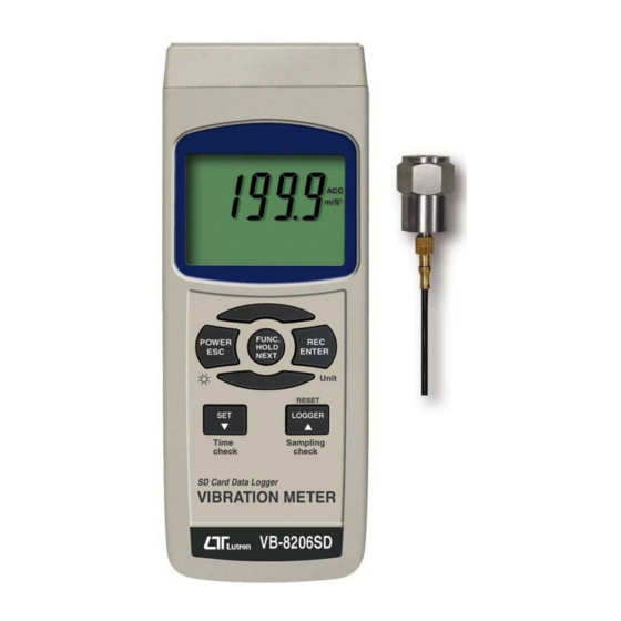
Page 10: Front Panel Description
3. FRONT PANEL DESCRIPTION Fig. 1 3-1 Display 3-2 Power Button ( ESC, Backlight Button ) 3-3 Hold Button ( Function Button, Next Button ) 3-4 REC Button ( Enter Button, Unit Button ) 3-5 SET Button ( Button, Time check Button ) ▼... -
Page 11: Measuring Procedure
4. MEASURING PROCEDURE 4-1 Preparation 1) Turn on the meter by pressing the " Power Button " ( 3-2, Fig. 1 ) momentarily. Pressing the " Power Button " ( 3-2, Fig. 1 ) continuously and > 2 seconds again will turn off the meter. -
Page 12: Unit Selection ( Acc./Velocity/Displacement Selection )
4-2 Unit selection ( Acc./Velocity/Displacement selection ) Select the desired display unit by pressing the " Unit Button " ( 3-4, Fig. 1 ) continuously ( not release the button ), the Display will show the following units according Acceleration/Velocity/Displacement in sequence. -
Page 13: Function Selection
Remark : 1. For the Acceleration measurement, the Display will show the indicator " ACC " 2. For the Velocity measurement, the Display will show the indicator " VEL. " 3. For the Displacement measurement, the Display will show the indicator " DISP p-p " 4. -
Page 14: Zero Adjustment Procedures
3. Peak measurement is intend to measure the peak vibration value. The Display will show the indicator " PEAK ". 4. After select the unit will be saved into the circuit with default. 5. Acceleration and Velocity measurement can select 3 function : RMS, PEAK, MAX HOLD * Typically, for Acceleration and Velocity measurement always select to the "... -
Page 15: Data Hold
4-5 Data Hold * Only available for the RMS function. During the measurement, press the " Hold Button " ( 3-3, Fig. 1 ) once will hold the measured value & the LCD will display a " HOLD " symbol. Press the "... -
Page 16: Lcd Backlight On/Off
4-7 LCD Backlight ON/OFF After power ON, the " LCD Backlight " will light automatically. During the measurement, press the " Backlight Button " ( 3-2, Fig. 1 ) once will turn OFF the " LCD Backlight ". Press the " Backlight Button " once again will turn ON the "... - Page 17 c. Time setting If the meter is used at first time, it should to adjust the clock time exactly, please refer chapter 7-1 ( page 21 ). d. Decimal forThe numerical data structure of SD card is default used the " . " as the decimal, for example "20.6"...
-
Page 18: Manual Datalogger ( Set Sampling Time = 0 Second )
b. Pause the datalogger During execute the Datalogger function , if press the " Logger Button " ( 3-6, Fig. 1 ) once will pause the Datalogger function ( stop to save the measuring data into the memory circuit temporally ). In the same time the text of "... -
Page 19: Check Time Information
Remark : During execute the Manual Datalogger, press the " ▼ Button " ( 3-5, Fig, 1 ) the lower no. ( position no. ) will flashing. It can use the " Button " ( 3-6, Fig. 1) or " ▲... - Page 20 2) If the first time to execute the Datalogger, under the route VBB01\, will generate a new file name VBB01001.XLS. After exist the Datalogger, then execute again, the data will save to the VBB01001.XLS until Data column reach to 30,000 columns, then will generate a new file, for example VBB01002.XLS 3) Under the folder VBB01\, if the total files more than 99 files, will generate anew route, such as...
-
Page 21: Saving Data From The Sd Card To The Computer
6. Saving data from the SD card to the computer ( EXCEL software ) 1) After execute the Data Logger function, take away the SD card out from the " SD card socket " ( 3-8, Fig. 1 ). 2) Plug in the SD card into the Computer's SD card slot ( if your computer build in this installation ) or insert the SD card into the "... -
Page 22: Advanced Setting
EXCEL graphic screen ( for example ) 7. ADVANCED SETTING Under do not execute the Datalogger function, press the " SET Button " ( 3-5, Fig. 1 ) continuously at least two seconds will enter the " Advanced Setting " mode. then press the "... -
Page 23: Set Clock Time ( Year/Month/Date, Hour/Minute/ Second )
Remark : During execute the " Advanced Setting " function, if press " Esc Button " ( 3-2, Fig. 1 ) once will exit the " Advanced Setting " function, the LCD will return to normal screen. 7-1 Set clock time ( Year/Month/Date, Hour/Minute/ Second ) When the lower display show "... -
Page 24: Decimal Point Of Sd Card Setting
7-2 Decimal point of SD card setting The numerical data structure of SD card is default used the " . " as the decimal, for example "20.6" "1000.53" . But in certain countries ( Europe ...) is used the " , " as the decimal point, for example "... -
Page 25: Set Sampling Time
7-4 Set beeper sound ON/OFF When the lower display show " bEEP " 1) Use the " Button " ( 3-6, Fig. 1 ) or " Button " ▲ ▼ ( 3-5, Fig. 1 ) to select the upper value to " yES " or "... -
Page 26: Power Supply From Dc Adapter
yES - Intend to format the SD memory card no - Not execute the SD memory card format 2) If select the upper to " yES ", press the " Enter Button " ( 3-4, Fig. 1 ) once again, the Display will show text "... -
Page 27: System Reset
10. SYSTEM RESET If the meter happen the troubles such as : CPU system is hold ( for example, the key button can not be operated... ). Then make the system RESET will fix the problem. The system RESET procedures will be either following method : During the power on, use a pin to press the "... - Page 28 Meter (9W 'D" Connector) Center Pin......Pin 4 (3.5 mm jack plug) Ground/shield.......Pin 2 2.2 K resistor Pin 5 The 16 digits data stream will be displayed in the following format : D15 D14 D13 D12 D11 D10 D9 D8 D7 D6 D5 D4 D3 D2 D1 D0 Each digit indicates the following status : Start Word D12, D11 Annunciator for Display...
-
Page 29: Classification Ranges
RS232 FORMAT : 9600, N, 8, 1 Baud rate 9600 Parity No parity Data bit no. 8 Data bits Stop bit 1 Stop bit 12. CLASSIFICATION RANGES For the valuation of machines and equipment in the ISO 2372 and VDI 2056, four different kinds of machine groups with four classification ranges and their limits for vibration severity ( mm/s ) are determined. - Page 30 Large machines on heavy foundations ( Group G ) Good 0 to 1.80 mm/s Acceptable 1.81 to 4.50 mm/s Still permissible 4.51 to 11.2 mm/s Dangerous > 11.2 mm/s Largest machines and turbo machines with a special foundations ( Group T ). Good 0 to 2.80 mm/s Acceptable...
-
Page 31: Patent
14. PATENT The meter ( SD card structure ) already get patent or patent pending in following countries : Germany JAPAN Nr. 20 2008 016 337.4 TAIWAN 3151214 M 358970 CHINA M 359043 ZL 2008 2 0189918.5 ZL 2008 2 0189917.0 Patent pending 1009-VB8206SD...
Need help?
Do you have a question about the VB-8206SD and is the answer not in the manual?
Questions and answers