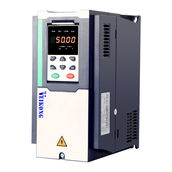
Veikong VFD500-PV Series Operation Manual
Solar pumping inverter
Hide thumbs
Also See for VFD500-PV Series:
- Operation manual (17 pages) ,
- Operation manual (50 pages) ,
- Operation manual (84 pages)
Table of Contents
Advertisement
Quick Links
Advertisement
Table of Contents

Related Manuals for Veikong VFD500-PV Series


Summary of Contents for Veikong VFD500-PV Series
- Page 1 Operation manual VFD500-PV Series Solar pumping Inverter...
-
Page 2: Electrical Specifications
Solar pumping inverter user manual 1、Electrical cable Connection Please follow the diagram below for wiring. And pay attention to the following issues: The power output of the PV panel is connected to the “+” and “-” terminals. Please note that the polarity is not reversed. - Page 3 Solar panels 3 phase power input Main circuit Control circuit 485+ RS485 port Connector slip 485- +24V +24V Start/stop terminal AO1、AO2 output: ~ ~ 10V/0 20mA +10V Water tank level Relay 1 output, feedback Default is fault signal output OFF OFF ON ON Grounding Wire Diagram of solar pump inverter...
-
Page 4: Keypad Display
2、Trial run(How to start solar pump inverter) Make sure all cables connections of solar panel and pump motor correct and no need to set any parameter,if you want to set parameter ,you can do as follows Step 1: Keypad control:Set motor parameter P11.02- P11.06 If dry run protection is required, measure the unload protection current according to the following method. -
Page 5: Parameter List
displayed . When the keyboard is displayed , press the key to enter the basic menu mode. 3.3 Error code:For other alarm codes, please refer to Chapter 5 of the manual. alarm code meaning Er.CCC Light weak fault, please refer to function code P47.05~P47.07 4、Parameter list Symbol Description:... - Page 6 Function Name Description Default Propert code algorithm. When the MPPT function is disabled, this value is the reference voltage. When the MPPT function is enabled, the inverter searches up and down from this value. for the maximum power point up or down 220V level DC 305V/ 380V Default DC 530V If the output frequency is lower than this value...
- Page 7 Function Name Description Default Propert code 24 group Pump dry run protection/unload detection parameter 0: No offload detection is performed; Dry run/Unload ☆ P24.12 1: Enable offload detection protection option Dry run/Unload 0.0 to 100.0% ☆ P24.13 0.0% detection level The percentage of motor rated current.
- Page 8 Function Name Description Default Propert code Enter the original password to enter the lock state; enter the same value twice in a row to change the password (clear the password if you enter 0 twice in a row). 0:NO ACTION 11:Restore default parameter except for motor parameter and auto-tune related parameter and ★...
- Page 9 Function Name Description Default Propert code Setting value depend on P03.16 P03.16 = 2, 0.00~600.00s; Depend on ☆ P03.02 Deceleration time 1 P03.16 = 1, 0.0s~6000.0s; model P03.16 = 0, 0s~60000s 0:linear VF 1:Multi-point VF 2:VF to the 1.3 ★ P12.00 VF curve 3:1.7 power...
- Page 10 Function Name Description Default Propert code 0:undervoltage stall disabled 1:undervoltage stall deceleration(decelerate to zero speed and run at zero speed) 2: undervoltage stall deceleration(decelerate to zero and stop) The undervoltage stall function reduces the motor power consumption or reduces the power consumption of the motor or turns it into a power generation operation to avoid the undervoltage fault on the DC side.
-
Page 11: Chapter 5 Fault Diagnosis And Solution
Chapter 5 Fault Diagnosis and Solution VFD500-PV inverter has 24 types of warning information and protection function. In case of abnormal fault,the protection function will be invoked, the inverter will stop output, and the faulty relay contact of the inverter will start, and the fault code will be displayed on the display panel of the inverter. Before consulting the service department, the user can perform self-check according to the prompts of this chapter, analyze the fault cause and find out solution. - Page 12 Fault Name Solutions Display Possible Causes 1: The output circuit is grounded or 1: Eliminate external faults. short circuited. 2: Perform the motor 2: Motor auto-tuning is not performed. auto-tuning. Over current 3: The deceleration time is too short. 3: Increase the decelerationtime. during Er.OC2 4: The voltage is too low.
- Page 13 Fault Name Solutions Display Possible Causes 1: Instantaneous power failure occurs on the input power supply. 1: Reset thefault. 2: The frequency inverter's input 2:Adjust voltage is not within the allowable Thevoltagetonormalrange. range. Low voltage Er.LU1 3: Ask for technical support 3: The DC bus voltage is abnormal.
- Page 14 Fault Name Solutions Display Possible Causes 1: The cable connecting the frequency 1:Eliminate external faults. inverter and the motor is faulty. 2: Check whether the 2: The frequency inverter's Power output Motor three phase winding Er.oLP three-phase outputs are unbalanced phase loss is normal.
- Page 15 Fault Name Solutions Display Possible Causes EEPROM 1、 Eeprom Operate too frequent 1、 Operate Eeprom suitable read- write Er.EEP 2、 Replace the main control board 2、 The EEPROM chip is damaged. fault 1、Confirm whether the load is off 1、 The frequency inverter running currentis 2、Check that the load is Off load Er.
- Page 16 ShenZhen VEIKONG Electric CO., Ltd. Factory Address: Block E01,first industrical park lingbei 5 road ,phoenix community,f uyong street , Bao'anDistrict, Shenzhen ,China R&D Center: Jin yu cheng building A,Bu Long Rd Bantian Town ,Longgang district Shenzhen City,China Technical Support Hotline: +86-0755-89587650...
Need help?
Do you have a question about the VFD500-PV Series and is the answer not in the manual?
Questions and answers