Table of Contents
Advertisement
Quick Links
NOTICE: See separate solenoid installation and maintenance
instructions for information on: Wiring, Solenoid Temperature,
Causes Of Improper Operation, and Solenoid Replacement.
DESCRIPTION
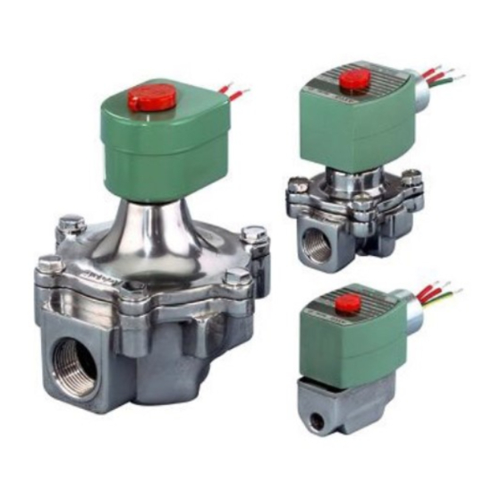
Series 8040 valves are 2-way normally closed direct-acting
solenoid valves designed for air or fuel gas service. Valve bodies
are made of rugged aluminum with trim and internal parts
made of steel and stainless steel. Series 8040 valves are
provided with a general purpose solenoid.
Series EF8040 valves are the same as Series 8040 except they
are provided with an explosionproof/watertight solenoid.
Provisions for Seat Leakage Testing
Series 8040H valves are provided with a 1/8I NPT downstream
side tap and pipe plug for checking seat leakage. Leakage
testing frequency shall be at least annually in accordance with
NFPA 86 or original equipment manufacturer recommendations.
T esting is also required after valve disassembly and reassembly for
inspection, cleaning or rebuilding.
OPERATION
Normally Closed:
Valve is closed when solenoid is
de-energized; open when energized.
NOTE: No minimum operating pressure differential required.
INSTALLATION
Check nameplate for correct catalog number, pressure,
voltage, frequency, and service. Never apply incompatible
fluids or exceed pressure rating of the valve. Installation and
valve maintenance to be performed by qualified personnel.
Temperature Limitations
For ambient an fluid temperatures, refer to chart below.
[
None, KF,
8040G6
SF or SC
8040G7
8040G7
HT, KH,
8040G8
ST or SU
None, KF,
8040H6
SF or SC
8040H7
8040H7
HT, KH,
8040H8
ST or SU
[ Includes catalog numbers with Prefix EF"
e
50 Hanover Road, Florham Park, New Jersey 07932
I
-20_F (-29_C) to 125_F (54_C)
-20_F (-29_C) to 140_F (60_C)
-40_F( -40_C) to 125_F (54_C)
-40_F (-40_C) to 140_F (60_C)
MM
All Rights Reserved.
I
I
Positioning
This valve is designed to perform properly when mounted in
any position. However, for optimum life and performance, the
solenoid should be mounted vertically and upright to reduce
the possibility of foreign matter accumulating in the
plugnut/core tube sub-assembly area.
Mounting
For mounting dimension of body boss or optional mounting
bracket, refer to Figure 2.
Piping
Connect piping to valve according to markings on valve body.
Apply pipe compound sparingly to male pipe threads only. If
applied to valve threads, the compound may enter the valve and
cause operational difficulty. Avoid pipe strain by properly
supporting and aligning piping. When tightening the pipe, do
not use valve or solenoid as a lever. Locate wrenches applied to
valve body or piping as close as possible to connection point.
Valves should be checked for external leakage at piping
connections after installation, see Testing for External Leakage
section.
Testing for External Leakage
1. Block gas flow on downstream side of valve.
2. Apply pressure to valve within nameplate rating and energize
solenoid.
3. Apply a soapy solution or a commercially available leak
detecting solution to the pipe connections and check for
bubbles. If the valve has been tested for seat leakage or
disassembled and reassembled for inspecting, cleaning or
rebuilding, then apply the solution around the base of the
retainer plate and pipe plug.
*DuPont Co. Registered Trademark
Printed in U.S.A.
www.ascovalve.com
I
.
Page 1 of 4
Advertisement
Table of Contents

Related Manuals for Asco 8040 Series


Summary of Contents for Asco 8040 Series
- Page 1 Positioning NOTICE: See separate solenoid installation and maintenance This valve is designed to perform properly when mounted in instructions for information on: Wiring, Solenoid Temperature, any position. However, for optimum life and performance, the Causes of Improper Operation, and Solenoid Replacement. solenoid should be mounted vertically and upright to reduce the possibility of foreign matter accumulating in the plugnut/core tube sub-assembly area.
- Page 2 Thoroughly clean all parts. If parts five cycles. Listen carefully for the solenoid coil to click are worn or damaged, install a complete ASCO Rebuild Kit. indicating proper operation. 3. Open the upstream manual gas cock. Program the control...
- Page 3 Rebuild Kits. When Ordering Rebuild Kits for ASCO valves, order the Rebuild Kit number stamped on the valve nameplate. If the number of the kit is not visible, order by indicating the number of kits required, and the Catalog 9.
- Page 4 2 places .750 screw 19,1 Mounting Bracket Dimensions Indicates that these parts are included in ASCO rebuild kit Figure 2. Series 8040 less solenoid. Page 4 of 4 Form No.V6602R5 50 Hanover Road, Florham Park, New Jersey 07932 www.ascovalve.com...
Need help?
Do you have a question about the 8040 Series and is the answer not in the manual?
Questions and answers