Baldor Flex+DriveII Operating Manual
Hide thumbs
Also See for Flex+DriveII:
- Installation manual (126 pages) ,
- Reference manual (20 pages) ,
- Installation manual (166 pages)
Table of Contents
Advertisement
Quick Links
Advertisement
Table of Contents

Related Manuals for Baldor Flex+DriveII


Summary of Contents for Baldor Flex+DriveII
- Page 1 SERVO DRIVE Flex+Drive Demonstration Unit Operating Manual 03/02 MN1917...
-
Page 3: Table Of Contents
Contents General Information ..........Introduction . - Page 4 5.5.4 Inserting command buttons ............. . 5.5.5 Adding program lines (code) .
-
Page 5: General Information
Baldor makes no representations or warranties with respect to the contents hereof and specifically disclaims any implied warranties of fitness for any particular purpose. The information in this document is subject to change without notice. Baldor assumes no responsibility for any errors that may appear in this document. - Page 6 1-2 General Information MN1917...
-
Page 7: Introduction
Introduction Features The Flex+Drive demonstration unit combines a Flex+Drive , a brushless servo motor and an input/output control panel. Features include: H Single axis AC brushless drive with integrated Mint controller H Direct connection to 115VAC or 230VAC single-phase (model dependent) H Programmable in Mint H Position, velocity and current control, preset and point to point moves, and gearing H Auto-tuning wizard (including position loop) and software oscilloscope facilities... - Page 8 2-2 Introduction MN1917...
-
Page 9: Setup
Setup Introduction The Flex+Drive demonstration unit is supplied with all necessary wiring already connected (except for upgrade kits). The user must only connect the AC power supply and serial cable. A PC will be necessary to run the WorkBench v5 software. 3.1.1 Controls and indicators Power on/off switch... -
Page 10: Drive Enable Switch
Installing the software The Flex+Drive will have been supplied with the Baldor Motion Toolkit v5 CD. 1. Insert the CD into the PC’s drive. 2. After a few seconds the setup wizard should start automatically. If the setup wizard does not appear, select Run... -
Page 11: Starting Workbench V5
3.1.5 Starting WorkBench v5 1. On the Windows Start menu, select Programs, WorkBench v5, WorkBench v5. WorkBench v5 will start, and the Tip of the Day dialog will be displayed. You can prevent the Tip of the Day dialog appearing next time by removing the check mark next to Show tips at startup. -
Page 12: Commissioning And Tuning
Commissioning and Tuning If you checked the Launch Commissioning Wizard option, the Commissioning Wizard will start automatically. Each type of motor and drive combination has slightly different performance characteristics. Before the Flex+Drive can be used to control the motor accurately, the Flex+Drive must be “tuned”. -
Page 13: Autotune Mode
3.2.2 Autotune mode When the Commissioning Wizard had finished, you are taken directly to Autotune mode. This tool performs a number of automatic tuning tests. It is best to use the default settings at this stage. 1. Click START. 2. In the dialog box that appears, click Yes to confirm. 3. - Page 14 4. In the Profile Parameters area, click Go. The Flex+Drive will perform a test move, causing the motor to turn. As the soon as the move is completed, WorkBench v5 will upload captured data from the Flex+Drive . The data will then be displayed in the Capture window as a graph.
-
Page 15: Basic Demonstrations
Basic Demonstrations Introduction This section demonstrates the basic controls and introduces the PLC Task and Presets modes. During some tests there may be a small delay before WorkBench v5 responds to control panel input. This is not caused by the Flex+Drive , but is a deliberate system refresh delay built in to WorkBench v5. -
Page 16: Analog Input
3. To activate a digital output, for example output 2, click in the Command window and type: OUTX.2 = 1 where 2 is the digital output to be activated. To deactivate the output, type: OUTX.2 = 0 The status of the output will be shown in the Spy window and on the control panel of the demonstration unit. The command OUTX can be incorporated into Mint programs to control outputs. -
Page 17: Demonstration Files
Demonstration files For demonstration purposes, a number of files are included on the CD-ROM. These include tables and sample applications for each type of demonstration unit, whether it is a Flex+Drive or MintDrive or designed for 115V or 230V operation. When selecting files for demonstrations, it is very important to use the correct set of files for your demonstration unit. -
Page 18: Preset Moves
Preset moves The Flex+Drive can store 16 preset moves. Presets can be selected and triggered using software (WorkBench v5 or a Mint program) or by using a combination of the digital inputs. In this demonstration the digital inputs will be used, operated by the control panel switches. -
Page 19: Testing Preset Moves
4.3.1 Testing Preset moves In this demonstration digital inputs will be used to trigger preset moves. 1. At the bottom of the Presets window, ensure that the Digital Inputs option is checked. This means the digital inputs will be used to control the preset index, not WorkBench v5. -
Page 20: Plc Task
PLC Task The PLC Task is a special task that can be setup to monitor various conditions and act upon them if they become true. PLC Task mode allows you to enter statements that respond to conditions. 1. In the Open dialog, select the file PLC.mnt, and click Open. 2. -
Page 21: Testing The Plc Task
Individual actions can be enabled by clicking the appropriate check box in the enable column. When the PLC Task is activated, only those actions that have been enabled will be evaluated. An individual action can be disabled even while the PLC Task is running. To disable an action that is not required, clear the action’s Enable check box and click Apply. - Page 22 4-8 Basic Demonstrations MN1917...
-
Page 23: Applications
Applications Introduction A number of applications are included on the CD to demonstrate some of the major features of the Flex+Drive All the necessary demonstration files should have already been copied to the host PC’s hard disk, as described in section 4.2.1. -
Page 24: Tool Changer
Tool changer In this demonstration a Mint program will be used to increase the speed of a typical tool changer application. This is achieved by ensuring that the specified tool is always selected by rotating the tool carousel by the ‘shortest path’. The tool positions are read from the presets table. -
Page 25: Plc Program
PLC program In this demonstration a Mint program will be used to perform the same actions as the PLC task. 1. If you are not working through the manual in sequence, you must download your parameter file. See section 4.2.1, steps 3. to 5. if you are not sure how to do this. 2. -
Page 26: Following
Following In this demonstration a Mint program will be used to demonstrate master encoder following. The program uses input switches 1, 4 and 5, the Analog Input 0 potentiometer, and the Master Encoder handwheel to control the program. 1. If you are not working through the manual in sequence, you must download your parameter file. See section 4.2.1, steps 3. -
Page 27: Changing The Follow Ratio
5.4.3 Changing the follow ratio The rate at which an axis follows the master can be adjusted, using a ‘software gearbox’. In the program, switches 2 and 3 can be used to set the ratio of the software gearbox, as described in Table 3: Ratio Input switch 2 Input switch 3... -
Page 28: Mintmt Activex Control
MintMT ActiveX control In this demonstration the ActiveX control will be used within Microsoft Excel to control the Flex+Drive A very simple form (window) will be designed, to represent a typical user application. 5.5.1 Preparing the Flex+Drive 1. If you are not working through the manual in sequence, you must download your parameter file. See section 4.2.1, steps 3. -
Page 29: Inserting The Activex Control
5.5.3 Inserting the ActiveX control The floating Toolbox contains a number of standard tools that can be used to construct new forms. However, the Mint ActiveX control is a special control so it must be added to the Toolbox before it can be used. 1. -
Page 30: Inserting Command Buttons
5.5.4 Inserting command buttons Nearly all Windows software uses familiar command buttons. A number of these need to be added to create the basic controls for the application. 1. In the Toolbox, click the CommandButton control. 2. In UserForm1, click and drag to draw a small rectangle. -
Page 31: Adding Program Lines (Code)
5.5.5 Adding program lines (code) Each command button requires some Visual Basic program code, so that when the user clicks the button, a function will be performed. 1. Right-click on the Init button, and choose View Code. This will display the underlying code for the button. The lines “Private Sub btnInit_Click”... -
Page 32: Opening The Example Vba File
5.5.6 Opening the example VBA file It is recommended that the file VBA.xls is used to continue the demonstration. The file contains comments to explain each section of code, together with an error handling routine. All code assumes that the Flex+Drive is connected to the host PC’s COM1 port. -
Page 33: Specifications
Specifications Introduction This section provides technical specifications for the Flex+Drive demonstration unit. 6.1.1 Specifications Description FPHDEMO/EN/115 FPHDEMO/EN/230 Input voltage 115VAC 230VAC Flex+Drive type FPH1A02TB-EN20 FPH2A02TB-EN20 Flex+Drive feedback type Encoder Motor BSM50N133AE Dimensions (HxWxD) 368mm x 144mm x 296mm (14.5in x 5.7in x 11.65in) Weight 7.7kg (17lb) Note: These specifications are for new Flex+Drive... - Page 34 6-2 Specifications MN1917...
-
Page 35: Upgrade Kit
Upgrade Kit Introduction A Flex+Drive demonstration unit can be created by upgrading an existing Flex+Drive demonstration unit. The upgrade kit provides the necessary parts to perform the upgrade. An upgraded unit will not be identical to a new unit. Existing demonstration units incorporate a resolver motor; correspondingly, the Flex+Drive used for the upgrade must be a model designed for resolver feedback (catalog numbers FPHxxxxxx-Rxxx). -
Page 36: Removing The Side Panel, Control Panel And Blanking Plate
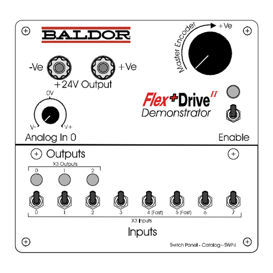
A.2.3 Removing the side panel, control panel and blanking plate The control panel is the large yellow panel at the base of the demonstration unit containing the switches and indicators. The blanking plate is screwed to the rear wall of the demonstration unit, and supports a rubber grommet through which the cables pass into the demonstration unit. -
Page 37: Building The New Unit
Building the new unit A.3.1 Inserting the cables The upgrade kit is supplied with three cables, described in Table 4. A cable’s number is marked on a label attached to the cable. Cable Purpose Flex+Drive connector Control panel connector LD5177A12 Main I/O cable 20-pin Phoenix plug 25-pin female D-type... -
Page 38: Attaching The Flex+Drive
A.3.4 Attaching the Flex+Drive 1. Take the Flex+Drive and mount it on the demonstration unit. The motor power cable and brown/blue/earth power cable group should be positioned above the Flex+Drive The I/O cable, the master encoder cable and the motor resolver cable should all be positioned below the Flex+Drive Tighten the three mounting bolts. - Page 39 Index ActiveX control, 5-6 LEDs. See Controls and indicators Applications, 5-1 Autotune mode, 3-5 MintMT ActiveX control, 5-6 Commissioning, 3-4 Wizard, 3-4 PLC program, 5-3 Control panel, 3-1 PLC Task, 4-6 Controls and indicators, 3-1 Preset moves, 4-4 Demonstrations Safety information, 1-1 Basic controls, 4-1–4-3 Setting up See also Controls and indicators...
- Page 40 Index MN1917...
- Page 42 Baldor Electric Company P.O. Box 2400 Ft. Smith, AR 72902-2400 Tel: (479) 646-4711 Fax: (479) 648-5792 www.baldor.com Printed in UK Baldor UK Ltd LT0162A00...
Need help?
Do you have a question about the Flex+DriveII and is the answer not in the manual?
Questions and answers