
Related Manuals for Baldor 23H series


Summary of Contents for Baldor 23H series
- Page 1 MN723H-10/95 11/28/95 1:04 AM Page 1 (Black plate) $25.00 SERIES 23H AC Servo Control INSTALLATION & OPERATING MANUAL 10/95 MN723...
-
Page 2: Table Of Contents
MN723H-10/95 11/28/95 1:04 AM Page 3 (Black plate) Table of Contents Section 1 General Information ............1-1 Introduction . - Page 3 Appendix A Baldor District Offices ........
-
Page 4: General Information
BALDOR and accepted by Buyer. Warranty of any product purchased by BALDOR from others is limited in time and scope to any warranty given BALDOR by such suppliers. -
Page 5: Safety Notice
MN723H-10/95 11/28/95 1:04 AM Page 6 (Black plate) Safety Notice THIS EQUIPMENT CONTAINS VOLTAGES WHICH MAY BE AS HIGH AS 1000 VOLTS AND ROTATING PARTS ON MOTORS AND DRIVEN MACHINES. HIGH VOLTAGE AND MOVING PARTS CAN CAUSE SERIOUS OR FATAL INJURY. ONLY QUALIFIED PERSONNEL FAMILIAR WITH THIS MANUAL AND ANY DRIVEN MACHINERY SHOULD ATTEMPT TO START-UP OR TROUBLESHOOT THIS EQUIPMENT. -
Page 6: Specifications
MN723H-10/95 11/28/95 1:04 AM Page 7 (Black plate) Specifications Power .75 - 37.2 KW (1 - 50 HP) @ 230 VAC .75 - 186.5 KW (1 - 250 HP) @ 460 VAC Input Frequency 50 / 60 HZ Output Voltage 0 to max input VAC Output Current See Control Rating Table... - Page 7 MN723H-10/95 11/28/95 1:04 AM Page 8 (Black plate) Functions Output status monitoring Digital speed control Parameter setting and display Fault log display Motor run and jog Local / Remote toggle LED Indicators Forward run command Reverse run command Stop command Jog active Remote Mount 100 feet max from control...
- Page 8 MN723H-10/95 11/28/95 1:04 AM Page 9 (Black plate) Other Analog Input: Full Scale Range 0 - 10 VDC Resolution 9 bits + sign Update Rate 2.0 msec Analog Outputs: 2 Assignable Full Scale Range 0 - 5 VDC Resolution 8 bits Update Rate 2.0 msec Digital Inputs:...
-
Page 9: Ratings
MN723H-10/95 11/28/95 1:05 AM Page 10 (Black plate) Diagnostic Indications: Current Sense Fault Regeneration (DB) Overload Ground Fault Soft Start Fault Instantaneous Overcurrent Undervoltage Invalid Power Base ID Ready Line Power Loss Parameter Loss Microprocessor Failure Overload Overtemperature (Motor or Control) Overvoltage Overspeed Following Error... - Page 10 MN723H-10/95 11/28/95 1:07 AM Page 11 (Black plate) Ratings Series 23H Stock Products QUIET 8.0 kHz PWM STANDARD 2.5 kHz PWM CATALOG INPUT CONSTANT TORQUE VARIABLE TORQUE CONSTANT TORQUE VARIABLE TORQUE VOLT SIZE SD23H2A03-E SD23H2A04-E SD23H2A07-E 15.2 17.5 SD23H2A10-E 15.2 17.5 15.2 17.5...
- Page 11 MN723H-10/95 11/28/95 1:07 AM Page 12 (Black plate) 1-8 GENERAL INFORMATION...
-
Page 12: Installation
Section 2 Installation This section covers all instructions for proper mounting and wiring of the Baldor Series 23H servo control. All tools required for normal installation should be available from any electrical service technician. If problems arise after installation, please refer to Section 4 Diagnostics and Troubleshooting. -
Page 13: Ac Line Impedance
FOR ALL CONTROL CATALOG LISTINGS. AC Line Impedance The Baldor Series 23H servo control requires a minimum line impedance of 3%. If the incoming power line does not have a minimum of 3% impedance, the addition of a line reactor will provide the needed impedance in most cases. - Page 14 MN723H-10/95 11/28/95 1:07 AM Page 15 (Black plate) Table 2.0A Input Current Requirements - Series 23H Stock Products Catalog Number Line Voltage Input Current SD23H2A03-E SD23H2A04-E SD23H2A07-E 15.2 SD23H2A10-E 15.2 SD23H2A15-E SD23H2A22-E SD23H2A30-ER SD23H2A45-ER SD23H2A55-ER SD23H4A02-E SD23H4A04-E SD23H4A05-E SD23H4A08-E SD23H4A11-E SD23H4A15-ER SD23H4A22-ER SD23H4A30-ER...
-
Page 15: Ac Power Connections
MN723H-10/95 11/28/95 1:07 AM Page 16 (Black plate) AC Power Connections The control requires input power protection in the form of either a circuit breaker or fuses. Circuit breakers are recommended. See Table 2.1 for fuse and breaker sizing. Connect the fused three phase AC power lines to the input power terminals L1, L2, and L3. -
Page 16: Wiring And Protective Devices
MN723H-10/95 11/28/95 1:07 AM Page 17 (Black plate) Wiring and Protective Devices This control must be provided with a suitable input power protection device. Use the recommended fuses or circuit breaker listed in Tables which follow. Input and output wire size is based on the use of 75 degree C rated copper conductor wire. - Page 17 MN723H-10/95 11/28/95 1:08 AM Page 18 (Black plate) Table 2.1A Series 23H Stock Product Wire Size and Protection Devices 230VAC Controls Catalog No. Max CT Input Input Fuse Input Fuse Wire Gauge Breaker Fast Acting Time Delay SD23H2A03-E SD23H2A04-E SD23H2A07-E SD23H2A10-E SD23H2A15-E SD23H2A22-E...
- Page 18 MN723H-10/95 11/28/95 1:08 AM Page 19 (Black plate) Table 2.1B Series 23H Product Wire Size and Protection Devices (Continued) 460VAC Controls Catalog No. Max CT Input Input Fuse Input Fuse Wire Gauge Breaker Fast Acting Time Delay SD23H4A02-E SD23H4A04-E SD23H4A05-E SD23H4A08-E SD23H4A11-E SD23H4A15-ER...
- Page 19 MN723H-10/95 11/28/95 1:08 AM Page 20 (Black plate) Table 2.2A Series 23H Stock Single Phase Rating Wire Size and Protection Devices 230 VAC Controls Catalog No. Max CT Input Input Fuse Input Fuse Wire Gauge Breaker Fast Acting Time Delay SD23H2A03-E SD23H2A04-E SD23H2A07-E...
- Page 20 MN723H-10/95 11/28/95 1:08 AM Page 21 (Black plate) Table 2.2B Series 23H Custom Single Phase Rating Product Wire Size and Protection Devices 460 VAC Controls Catalog No. Max CT Input Input Fuse Input Fuse Wire Gauge Breaker Fast Acting Time Delay SD23H4A02-E SD23H4A04-E SD23H4A05-E...
- Page 21 MN723H-10/95 11/28/95 1:08 AM Page 22 (Black plate) Connect an earth ground to the control according to applicable local electrical codes. The earth ground should be connected to the control chassis ground lug. Also connect motor ground to control ground lug. The use of a power disconnect is recommended between the input power and the control to provide a fail safe method to disconnect the control from the input power.
-
Page 22: Operating 460 Vac Control On 380-400 Vac
MN723H-10/95 11/28/95 1:08 AM Page 23 (Black plate) Operating a 460 VAC Control on 380-400 VAC Size A and B controls may be used directly with a 380-400 VAC power source, no reconfiguration of the control is necessary. Control sizes C, D, E, and F all must be reconfigured for operation on the reduced line voltage. Specifically, the control transformer (see Figure 2-2) must have the wire on terminal 5 moved to terminal 4 as shown below. -
Page 23: Single Phase Derating
MN723H-10/95 11/28/95 1:09 AM Page 24 (Black plate) 15-60 HP 460 VAC controls: Jumper JP3 on the gate drive circuit board (Figure 2-3) must be moved from position "A" to position "B". The gate drive circuit board is under the main control board. For controls equipped with gate drive board No. - Page 24 MN723H-10/95 11/28/95 1:09 AM Page 25 (Black plate) Figure 2-4 Motor Connections without Output Contactor B+\R1 MOTOR GND T3 50/60 HZ 3 Phase Power Breaker or Fuse Protection - Customer Option, Subject to Local Codes See Appendix C For Recommended Terminal Tightening Torques A motor circuit contactor is recommended to provide a positive disconnection to prevent motor rotation which could pose a safety hazard to personnel or equipment.
-
Page 25: Dynamic Braking
Identify the middle number of the controller and determine which dynamic brake hardware is required based on the model number suffix (-E, -ER). Select the required hardware from the Baldor Electric Company 501 catalog or from the hardware listings that follow. - Page 26 MN723H-10/95 11/28/95 1:09 AM Page 27 (Black plate) To determine average regenerated watts caused by lowering a load, use the formula: D r x lbs x FPM x EFF W r = where: = weight to be lowered = speed in ft/minute = mechanical efficiency as a decimal To determine dynamic braking duty cycle, use the formula: D r =...
- Page 27 These controls have the dynamic braking transistor installed at the factory but no dynamic braking resistors. Should you need dynamic braking capacity optional separately mounted external braking resistor kits or assemblies are available from Baldor. One hardware configuration is the RG kit which comes with resistors mounted on brackets and the resistors wired together for the correct resistance required by the control's DB transistor.
- Page 28 MN723H-10/95 11/28/95 1:09 AM Page 29 (Black plate) Table 2.3 Dynamic Braking Resistor Assemblies (RGA) RGA Assemblies include braking resistors completely assembled and mounted in a NEMA 1 enclosure. For 1-10 HP (E) controls select braking resistor that has the correct ohm value for the control and adequate continuous watts capacity.
- Page 29 MN723H-10/95 11/28/95 1:09 AM Page 30 (Black plate) Figure 2-6 Wiring for RGA Assembly Optional Dynamic Brake (RGA) B+\R1 MOTOR GND T3 50/60 HZ 3 Phase Power Breaker or Fuse Protection - Customer Option See Appendix C For Recommended Terminal Tightening Torques 2-18 INSTALLATION...
-
Page 30: Resolver Wiring
MN723H-10/95 11/28/95 1:09 AM Page 31 (Black plate) Resolver Wiring The 23H control requires the use of resolver feedback from the motor shaft. The resolver power and signal connections are made to the control's J1 terminal strip. Resolver wiring must be twisted shielded pairs, #22 AWG minimum size, 150' maximum, with an insulated overall shield. - Page 31 MN723H-10/95 11/28/95 1:09 AM Page 32 (Black plate) Connecting the Resolver CAUTION: DO NOT CONNECT ANY SHIELDS TO THE MOTOR FRAME. RESOLVER POWER SUPPLY OUTPUT PROVIDED BY THE CONTROL AT J1- 27 IS REFERENCED TO CIRCUIT BOARD COMMON. DO NOT CONNECT THIS OUTPUT TO GROUND OR ANOTHER POWER SUPPLY OR DAMAGE TO THE CONTROL MAY RESULT.
-
Page 32: Incremental Position Output
MN723H-10/95 11/28/95 1:09 AM Page 33 (Black plate) Incremental Position Output The control provides a simulated encoder output of the motor mounted resolver on terminal strip J1 pins 31-38 as shown in Figure 2-10. This output simulates a 1024 line encoder with quadrature outputs. -
Page 33: Remote Keypad Mounting
Page 34 (Black plate) Remote Keypad Mounting Instructions for Remote Keypad Mounting Using Optional Baldor Keypad Extension Cable The keypad assembly (DC00005A-00) comes complete with the screws and gasket required to mount it to an enclosure. When the keypad is properly mounted to a NEMA Type 4 enclosure, it retains the Type 4 rating. - Page 34 MN723H-10/95 11/28/95 1:09 AM Page 35 (Black plate) Figure 2-12 Remote Keypad Mounting Template 4.000 2.500 FOUR PLACES 8-32 TAP USE DRILL #29 8-32 CLEARANCE USE #19 OR 0.166" 1-11/16" DIAMETER HOLE USE 1.25" CONDUIT KNOCKOUT 1.250 SCALE NOT TO BE ALTERED DIMENSIONS CAN BE DISTORTED DUE TO REPRODUCTION INSTALLATION 2-23...
-
Page 35: Logic And Control Wiring
MN723H-10/95 11/28/95 1:10 AM Page 36 (Black plate) Logic and Control Wiring All logic and control connections are made at the 44 pin terminal strip J1. The terminal strip is divided into a lower and an upper row. The lower row carries pins numbered 1-22 with the upper row being 23-44. -
Page 36: Analog Inputs And Outputs
MN723H-10/95 11/28/95 1:10 AM Page 37 (Black plate) Analog Inputs and Outputs Figure 2-14 Analog Inputs and Outputs ANALOG GND COMMAND POT 5K OHM ANALOG INPUT 1 or 0-10 VDC ON PINS 1 & 2 POT REFERENCE DIFFERENTIAL ± 5V, ±10V ANALOG INPUT + 2 or 4-20 mA INPUT ANALOG INPUT - 2... - Page 37 MN723H-10/95 11/28/95 1:10 AM Page 38 (Black plate) Analog Outputs Two programmable analog outputs are provided on J1-6 and J1-7. These outputs are scaled 0 - 5 VDC (1ma Max output current) and can be used to provide real-time status of various control conditions.
-
Page 38: External Trip Input
MN723H-10/95 11/28/95 1:10 AM Page 39 (Black plate) OVERLOAD Accumulated current X time, OVERLOAD occurs at +5V. PH 2 CURRENT Sampled AC phase 2 motor current, 2.5V = zero current, 0V = negative rated peak current, +5V = positive rated peak current. PH 3 CURRENT Sampled AC phase 2 motor current, 2.5V = zero current, 0V = negative rated peak current, +5V = positive rated peak current. -
Page 39: Opto-Isolated Outputs
MN723H-10/95 11/28/95 1:10 AM Page 40 (Black plate) Opto-isolated Outputs Four programmable Opto-isolated outputs are available at terminals J1-19 through J1-22. These outputs can be used to monitor various control conditions. Powering the Opto-isolated Outputs The Opto-isolated outputs may be configured as sinking or sourcing. All must be configured the same. - Page 40 MN723H-10/95 11/28/95 1:10 AM Page 41 (Black plate) Opto-Isolated Output Selection Four independent programmable opto-isolated outputs are available on the J1 connector for external monitoring of drive conditions. These outputs are available on terminals J1-19 thru J1-22. These outputs require 5-30 VDC to operate. Each will sink up to 60mA maximum. The voltage drop across the output may be as high as 1VDC (TTL compatible).
-
Page 41: Opto-Isolated Inputs
MN723H-10/95 11/28/95 1:10 AM Page 42 (Black plate) OVER-TEMP WARN Closed when the control heat sink detector senses the control is within 3 Deg C of tripping on INT OVER-TEMP. MOTOR DIRECTION Closed when reverse input direction command is received, open for forward. - Page 42 MN723H-10/95 11/28/95 1:10 AM Page 43 (Black plate) Figure 2-16 Opto Input Power Configurations USER +10-30VDC ENABLE ENABLE FORWARD FORWARD REVERSE REVERSE INPUT #1 INPUT #1 INPUT #2 INPUT #2 INPUT #3 INPUT #3 INPUT #4 INPUT #4 INPUT #5 INPUT #5 INPUT #6 INPUT #6...
-
Page 43: Operating Mode Connection Diagrams
MN723H-10/95 11/28/95 1:10 AM Page 44 (Black plate) Operating Mode Connection Diagrams Six different operating modes are available in the Series 23H servo control. These operating modes define the basic motor control setup and the operation of the input and output terminals. These operating modes are selected by programming the Operating Mode parameter in the Input programming Block. -
Page 44: Standard Run 3 Wire Control Mode
MN723H-10/95 11/28/95 1:10 AM Page 45 (Black plate) Standard Run 3 Wire Control Mode Figure 2-18 Standard Run 3-Wire Connection Diagram ANALOG GND SINE + ANALOG INPUT 1 SINE – 5kOhm COMMAND POT POT REFERENCE COSINE + 0-5VDC OR ANALOG INPUT +2 COSINE –... -
Page 45: Speed, Two Wire Control Mode
MN723H-10/95 11/28/95 1:10 AM Page 46 (Black plate) 15 Speed 2-Wire Control Mode Figure 2-19 15 Speed 2-Wire Control Connection Diagram SINE + SINE – COSINE + NO CONNECTIONS COSINE – RESOLVER INPUT EXCITATION + ANALOG OUT 1 COMMON PROGRAMMABLE 0-5V OUTPUT (FACTORY PRESET: SPEED) ANALOG OUT 2 SHIELD PROGRAMMABLE 0-5V OUTPUT (FACTORY PRESET: CURRENT) - Page 46 MN723H-10/95 11/28/95 1:10 AM Page 47 (Black plate) Switch Truth Table for 15 Speed, 2 Wire Control Mode FUNCTION J1-11 J1-12 J1-13 J1-14 Preset 1 Open Open Open Open Preset 2 Closed Open Open Open Preset 3 Open Closed Open Open Preset 4 Closed...
- Page 47 MN723H-10/95 11/28/95 1:10 AM Page 48 (Black plate) Bipolar Speed or Torque Control Mode In addition to individual motor bipolar speed or torque control, this mode of operation allows the user to store up to four (4) different complete sets of motor parameters. Why multiple parameter sets? An example might be to run a motor connected Wye and then to run it at another time connected Delta;...
- Page 48 MN723H-10/95 11/28/95 1:10 AM Page 49 (Black plate) NOTE: FOR 4-20MA INPUT MOVE JUMPER JP1 ON THE MAIN CONTROL BOARD TO THE LEFT TWO PINS. J1-8 OPEN disables the control & motor coasts to a stop. CLOSED allows current to flow in the motor and produce torque.
- Page 49 Mode is Enabled (J1-13) SERIAL EXB Setpoint Adjustment Limit NONE=FACTORY PRESET w/ Integral Clamp To Max Limit Value “PROCESS FEEDFORWARD” Existing Baldor Control System COMMAND SELECT Select The Source Through Differential Parameter Adjustment. Available Sources: Gd s POTENTIOMETER = F.P.
- Page 50 MN723H-10/95 11/28/95 1:11 AM Page 51 (Black plate) Figure 2-22 Process Mode Connection Diagram ANALOG GND SINE + ANALOG INPUT 1 SINE – 5kOhm COMMAND POT POT REFERENCE COSINE + ANALOG INPUT +2 DIFFERENTIAL ± 5VDC, ± 10VDC COSINE – RESOLVER OR 4-20 mA INPUT ANALOG INPUT -2...
- Page 51 The best motor efficiency is obtained at all speeds with the variable speed system. Figure 2-23 HVAC Process Mode Example HVAC Blower Intake Plenum Air Pressure Sense Port Building Plenum Baldor Vector/Inverter Drive Motor Setpoint Setpoint 1/4" Hose Potentiometer Source Adjustment...
-
Page 52: Pre-Operation Checklist
MN723H-10/95 11/28/95 1:11 AM Page 53 (Black plate) Pre-Operation Checklist Check of Electrical Items CAUTION: AFTER COMPLETING THE INSTALLATION STEPS AND BEFORE APPLYING LINE POWER TO THE SYSTEM, DOUBLE CHECK THE FOLLOWING ITEMS: Verify AC line voltage at source matches control rating. Inspect all power terminations for accuracy, workmanship and tightness. - Page 53 Page 54 (Black plate) Minimum Required Parameter Settings and Control Set-up Checklist If you are familiar with programming Baldor controls continue below. If not, proceed to Section 3 before applying power to the drive. NOTE: THIS LIST IS THE MINIMUM REQUIRED PROCEDURE TO PROGRAM THE CONTROL FOR OPERATION OF THE CONTROL FROM THE KEYPAD FOR INITIAL START-UP.
-
Page 54: Keypad Programming And Operation
MN723H-10/95 11/28/95 1:11 AM Page 55 (Black plate) Section 3 Keypad Programming and Operation Using the Keypad The programming and basic operation of the control is done with simple keystrokes on the keypad located on the face of the control. The keypad is used to program the control parameters; to operate the motor when programmed for the KEYPAD ONLY MODE or the local mode when the control is programmed to operate in one of the remote modes or the SERIAL MODE;... - Page 55 MN723H-10/95 11/28/95 1:11 AM Page 56 (Black plate) Keypad Key Functions Used to run the motor at the preprogrammed jog speed. After the jog key has been pressed, use the FWD or REV keys to run the motor in the direction that is needed.
- Page 56 MN723H-10/95 11/28/95 1:11 AM Page 57 (Black plate) ARROW KEYS In the LOCAL MODE the ARROW keys are used to increase or decrease the motor speed. In the PROGRAM MODE the ARROW keys are used to scroll through the parameter options and to change parameter values. ENTER Used to provide movement between programming blocks and saving user entered data.
- Page 57 MN723H-10/95 11/28/95 1:11 AM Page 58 (Black plate) LEVEL 2 BLOCKS Output Limits Security Auto Tuning Operating Zone Security State Calc Presets Min Output Speed Access Timeout Cmd Offset Trim Max Output Speed Access Code Cur Loop Comp Pk Current Limit Resolver Align PWM Frequency Motor Data...
-
Page 58: Display Mode
MN723H-10/95 11/28/95 1:11 AM Page 59 (Black plate) Display Mode During normal operation the controller is in the DISPLAY MODE and the keypad displays the status of the control. There are several output status values that can be monitored. When the control is in the DISPLAY MODE the information shown below is displayed. -
Page 59: Program Mode
MN723H-10/95 11/28/95 1:11 AM Page 60 (Black plate) Program Mode Use the PROGRAM MODE to customize the control to suit a variety of applications by programming the operating parameters. From the DISPLAY MODE press the PROG key to access the PROGRAM MODE. - Page 60 MN723H-10/95 11/28/95 1:11 AM Page 61 (Black plate) Decel Time #1 and Decel Time #2 - Sets the time in seconds for the output speed command to decrease linearly from the maximum speed specified in the MAX OUTPUT SPEED parameter to 0 RPM.
- Page 61 MN723H-10/95 11/28/95 1:11 AM Page 62 (Black plate) The factory preset is Remote On. Pressing the Stop Key (if programmed active) while in remote control automatically selects LOCAL mode of operation to prevent a restart command. Keypad Stop Mode - Selects if the motor will "coast" or "regen" to a stop. In the coast mode power to the motor will be turned off and the motor will coast to a stop.
- Page 62 MN723H-10/95 11/28/95 1:11 AM Page 63 (Black plate) NOTE: WHEN USING A 4-2OMA INPUT, JUMPER JP1 ON THE MAIN CONTROL BOARD MUST BE MOVED TO THE LEFT TWO PINS. ANA CMD Inverse - This parameter inverts the analog input command. Choice is ON or OFF. When set to ON the control recognizes a high level command signal as a low speed output command and a low level command signal as a high speed output command.
- Page 63 Brushless Control Block Resolver Alignment - A numerical alignment value between the motor and the resolver set by the auto tuning procedure. The factory preset value is 22.3 degrees and is correct for all standard Baldor BSM motors. Speed Filter - Sets the number of scans by the control microprocessor to filter the resolver signal input to the control.
- Page 64 MN723H-10/95 11/28/95 1:11 AM Page 65 (Black plate) Level 2 Programming Blocks Output Limits Block Operating Zone - This parameter sets up the Operating Zone of the control for Standard PWM output bridge carrier frequency (2.5KHz) or Quiet PWM output bridge carrier frequency (8.0KHz) in a Constant Torque mode which has a 200% 3 second with a 150% 60 second peak overload capacity or a Variable Torque mode which has a 115% peak overload capacity for 60 seconds.
- Page 65 MN723H-10/95 11/28/95 1:11 AM Page 66 (Black plate) Torque Rate Limit - Limits the rate of change of a torque command. The adjustable range is from 0-10.00 seconds. The factory preset is 0.00 seconds. Custom Units Block The custom units block parameters are used to set up a keypad Output Rate display of units that are meaningful to your operation.
- Page 66 MN723H-10/95 11/28/95 1:11 AM Page 67 (Black plate) NOTE: THE FOLDBACK SELECTION MAY NOT BE AVAILABLE ON SOME EARLY VERSIONS OF SOFTWARE. External Trip - This parameter programs the control to expect to see a Normally Closed (NC) switch at the external trip input terminal at the main control board's terminal strip. The choice is to turn it ON or turn it OFF.
- Page 67 MN723H-10/95 11/28/95 1:11 AM Page 68 (Black plate) Homing Offset - This parameter sets distance past the index marker at which the motor will stop. The distance is set by the number of digital pulses that the control expects before stopping motor rotation.
- Page 68 The factory preset is 9999. If you cannot gain entry into the security area to change a parameter. Please contact BALDOR. Be prepared to give the five digit code located on the lower right hand side of the keypad display when prompted for a security code.
- Page 69 MN723H-10/95 11/28/95 1:11 AM Page 70 (Black plate) Brake Adjust Block Resistor Ohms - This sets the Dynamic Braking Resistor value in Ohms. The dynamic braking resistor can be internal (-E models) or external using optional RG, RGA or RBA assemblies. Care should be exercised in selecting the proper amount of minimum resistance.
- Page 70 MN723H-10/95 11/28/95 1:12 AM Page 71 (Black plate) Set Pt Adj Limit - This parameter sets the maximum speed correction the motor will make in response to the maximum feedback setpoint error. The parameter is programmed as a +/- percentage of the Max Motor Speed parameter. For example, if the Max Motor Speed is 175O RPM, the setpoint feedback error is 100% and the Setpoint Adjustment Limit is programmed to be 10%, the maximum speed the motor will run in response to the setpoint feedback error is +/- 175 RPM.
- Page 71 MN723H-10/95 11/28/95 1:12 AM Page 72 (Black plate) Auto-Tuning Block NOTE: OCCASIONALLY THE AUTO-TUNING TESTS CANNOT BE RUN ON AN APPLICATION. THIS MAY BE BECAUSE THE LOAD CANNOT BE UNCOUPLED FROM THE MOTOR OR SOME OTHER REASON. IF THIS IS THE CASE, THE CONTROL CAN BE MANUALLY TUNED BY PROGRAMMING IN THE NECESSARY PARAMETER VALUES BASED ON CALCULATIONS YOU DO.
-
Page 72: Accessing Parameter Blocks For Programming
MN723H-10/95 11/28/95 1:12 AM Page 73 (Black plate) Accessing Parameter Blocks for Programming Use the following procedure to access parameter blocks to program the control. Action Description Display Comments Apply Power Display illuminates Logo display for B A L D O R for 5 seconds MOTORS &... -
Page 73: Programming Or Changing Parameters When Security Code Not Used
MN723H-10/95 11/28/95 1:12 AM Page 74 (Black plate) Programming or Changing Parameters when Security Code Not Used Use the following procedure to program or change a parameter already programmed into the control when a security code is not being used. Example below changes operating mode from keypad to bipolar. -
Page 74: System Security
MN723H-10/95 11/28/95 1:12 AM Page 75 (Black plate) System Security Access to programmed parameters can be protected by use of the security code feature. Security is enabled, and the security code is defined by setting the parameters in the Level 2 Security Control programming block. -
Page 75: Program Or Change Security System
MN723H-10/95 11/28/95 1:12 AM Page 76 (Black plate) Program or Change Security System Action Description Display Comments ACTION DESCRIPTION DISPLAY COMMENTS Logo display Apply Power 5 seconds M O T O R S & D R No faults present, STOP M O T O R Local keypad mode. -
Page 76: Program Or Change Security System Access Timeout Parameter
MN723H-10/95 11/28/95 1:12 AM Page 77 (Black plate) Program or Change the Security System Access Timeout Parameter ACTION DESCRIPTION DISPLAY COMMENTS Action Description Display Comments Logo display Apply Power 5 seconds M O T O R S & D R No faults present, STOP M O T O R... - Page 77 MN723H-10/95 11/28/95 1:12 AM Page 78 (Black plate) Programming or Changing Parameters with a Security Code in Use Use the following procedure to program or change a parameter already programmed into the control that has a security code enabled. Action Description Display Comments...
-
Page 78: Operating The Control From The Keypad
MN723H-10/95 11/28/95 1:12 AM Page 79 (Black plate) Operating the Control from the Keypad The control can operate the motor in three (3) different ways from the keypad. JOG Command Speed adjustment with Keypad entered values. Speed adjustment using the Keypad arrow keys. The following keypad key sequence procedures outline each. -
Page 79: Keypad Entered Speed Adjustment
MN723H-10/95 11/28/95 1:12 AM Page 80 (Black plate) Operating the Control From the Keypad - Keypad Entered Speed Adjustment ACTION DESCRIPTION DISPLAY COMMENTS Logo display Apply Power for 5 seconds M O T O R S & D R No faults present local STOP M O T O R Display mode... -
Page 80: Arrow Key Speed Adjustment
MN723H-10/95 11/28/95 1:12 AM Page 81 (Black plate) Operating the Control from the Keypad - Arrow Key Speed Adjustment ACTION DESCRIPTION DISPLAY COMMENTS Logo display Apply Power for 5 seconds M O T O R S & D R No faults present local STOP M O T O R Display mode... -
Page 81: Reset Control To Factory Settings
MN723H-10/95 11/28/95 1:12 AM Page 82 (Black plate) Reset Control to Factory Settings Sometimes it is necessary to recover the factory preset parameter values. Follow this procedure to do so. Note that all of your specific application parameters will be lost when resetting the control to factory presets. - Page 82 MN723H-10/95 11/28/95 1:13 AM Page 83 (Black plate) Display Key Functions: The display key can be used to view different operating conditions, fault log information and diagnostic information. Accessing Display Screens Action Description Display Comments Shows motor speed; direction STOP M O T O R Press DISP Key of rotation;...
- Page 83 MN723H-10/95 11/28/95 1:13 AM Page 84 (Black plate) 3-30 KEYPAD PROGRAMMING AND OPERATION...
-
Page 84: Diagnostic Info And Troubleshooting
MN723H-10/95 11/28/95 1:13 AM Page 85 (Black plate) Section 4 Diagnostic Info and Troubleshooting How to Access Diagnostic Information Diagnostic Menu Action Description Display Comments Logo display Apply Power for 5 seconds No faults present local STOP M O T O R Display mode keypad mode. - Page 85 MN723H-10/95 11/28/95 1:13 AM Page 86 (Black plate) Diagnostic Menu Continued Action Description Display Comments STOP Displays operating DC bus Press DISP Key Access next diagnostic screen voltage, and direction of VOLTAGE rotation Display % of overload current STOP OVRLD Press DISP Key Access next diagnostic screen remaining &...
-
Page 86: No Keypad Display
MN723H-10/95 11/28/95 1:13 AM Page 87 (Black plate) No Keypad Display There can be no display in the keypad depending upon the level of contrast for which the display is set. The following procedure provides the steps necessary to adjust the contrast of the display. Action Description Display... -
Page 87: How To Access The Fault Log
MN723H-10/95 11/28/95 1:13 AM Page 88 (Black plate) How to Access the Fault Log When a fault condition occurs, motor operation stops and a fault code is displayed on the Keypad display. The control keeps a log of up to the last 31 faults. If more than 31 faults have occurred the oldest fault will be deleted from the fault log to make room for the newest fault. - Page 88 MN723H-10/95 11/28/95 1:13 AM Page 89 (Black plate) Clearing the Fault Log Use the following procedure to clear the Fault Log. Action Description Display Comments Logo display Apply Power Display illuminates 5 seconds M O T O R S & D R No faults present, STOP M O T O R...
- Page 89 MN723H-10/95 11/28/95 1:13 AM Page 90 (Black plate) Fault Messages When a fault condition occurs, motor operation stops and a fault is displayed on the operator keypad. A list of the possible faults and their descriptions follows. Refer to the Troubleshooting section which follows for recommended corrective actions.
-
Page 90: Troubleshooting
MN723H-10/95 11/28/95 1:13 AM Page 91 (Black plate) Troubleshooting It is important to familiarize yourself with the following information before attempting any troubleshooting or service of the control. Most troubleshooting can be performed using only a digital voltmeter having an input impedance exceeding 1 megohm. In some cases an oscilloscope with 5 MHZ minimum bandwidth may be useful. - Page 91 MN723H-10/95 11/28/95 1:13 AM Page 92 (Black plate) Faults and Possible Causes SYMPTOM POSSIBLE CAUSE CORRECTIVE ACTION BASE ID FLT Invalid power base ED number. Press RESET key. If fault remains call factory. CURRENT SENS FLT Open circuit between control board and check connections from control board to current current sensor.
- Page 92 MN723H-10/95 11/28/95 1:14 AM Page 93 (Black plate) SYMPTOM POSSIBLE CAUSE CORRECTIVE ACTION MOTOR WILL NOT Improper speed command. Verify control is receiving proper command START signal at input terminal strip. Incorrect COMMAND SELECT parameter. Match COMMAND SELECT parameter with user interface.
- Page 93 MN723H-10/95 11/28/95 1:14 AM Page 94 (Black plate) SYMPTOM POSSIBLE CAUSE CORRECTIVE ACTION FOLLOWING ERROR Speed proportional gain too low. Increase SPEED PROP GAIN parameter setting. FAULT Current limit set too low. Increase CURRENT LIMIT parameter setting. Accel/decel time(s) too short. Lengthen ACCEL/DECEL parameter time(s).
- Page 94 MN723H-10/95 11/28/95 1:14 AM Page 95 (Black plate) SYMPTOM POSSIBLE CAUSE CORRECTIVE ACTION POWER BASE FLT Broken or misaligned encoder coupling. Check encoder coupling: align or replace. Encoder bearing failure. Replace encoder and align during installation. Excessive current draw. Disconnect motor wiring and retry. Contact Power device desaturated.
- Page 95 MN723H-10/95 11/28/95 1:14 AM Page 96 (Black plate) SYMPTOM POSSIBLE CAUSE CORRECTIVE ACTION OVERCURRENT FLT CURRENT LIMIT parameter set too low. Increase CURRENT LIMIT parameter setting. Accel/Decel time(s) too short. Increase ACCEL/DECEL parameter time(s). Broken or misaligned encoder coupling. Check encoder coupling: align or replace. Encoder bearing failure.
-
Page 96: Improper Motor Operation
MN723H-10/95 11/28/95 1:14 AM Page 97 (Black plate) Improper Motor Operation Wrong Response to Speed Commands Input common mode voltage may be exceeded. Maximum common mode voltage at terminals J1-4 and J1-5 is ± 15 volts relative to chassis common. Connect control input source common to the control common to minimize common mode voltage. - Page 97 MN723H-10/95 11/28/95 1:14 AM Page 98 (Black plate) Speed Prop Gain Parameter This parameter is located in the Level 1, Brushless Control Block. The Speed Prop Gain parameter is normally preset or auto-tuned. This gain may be increased or decreased to suit the application. Increasing the Speed Prop Gain parameter will result in faster response, excessive proportional gain will cause overshoot and ringing.
- Page 98 Output/E = Kp + KI / s = Kp (s + Ki/Kp) /s. The second equation shows that the ratio of Ki/Kp is a frequency in radians/sec. In the Baldor series 18H AC vector controller, the integral gain has been redefined to be,...
- Page 99 MN723H-10/95 11/28/95 1:14 AM Page 100 (Black plate) 4-16 DIAGNOSTIC INFO AND TROUBLESHOOTING...
-
Page 100: Appendix A Baldor District Offices
MN723H-10/95 11/28/95 1:14 AM Page 101 (Black plate) Appendix A Baldor District Offices UNITED STATES NEW JERSEY INTERNATIONAL SALES MEXICO PHILADELPHIA CALLE PABLO UCELLO NO. 27 100 W NARBERTH TERRACE COL. NOCHE BUENA FORT SMITH, AR ARIZONA P O BOX 597 03710 MEXICO D.F., MX... -
Page 101: Appendix B Control Watts Loss For Enclosure Sizing
MN723H-10/95 11/28/95 1:14 AM Page 102 (Black plate) Appendix B Control Watts Loss for Enclosure Sizing All motor controls using power transistors to control voltage and current output to a motor generate some heat. This heat is a normal part of switching the power devices "on" and "off". The amount of heat generated by each must be taken into account when installing them in an enclosure. - Page 102 MN723H-10/95 11/28/95 1:15 AM Page 103 (Black plate) Appendix C Terminal Torque Specifications Series 23H Stock Product Tightening Torque 230 VAC Power TB1 Control J1 Catalog No. Lb-in Lb-in SD23H2A03-E SD23H2A04-E SD23H2A07-E SD23H2A10-E SD23H2A15-E SD23H2A22-E SD23H2A30-ER SD23H2A45-ER SD23H2A55-ER Series 23H Custom Products Tightening Torque 460 VAC Power TB1...
-
Page 103: Appendix D Recommended Wire Sizes And Protective Devices
MN723H-10/95 11/28/95 1:16 AM Page 104 (Black plate) Appendix D Recommended Wire Sizes and Protective Devices This control must be provided with a suitable input power protection device. Use the recommended fuses or circuit breaker listed on Table 2.1 which follows. Input and output wire size is based on the use of 75 degree C rated copper conductor wire. - Page 104 MN723H-10/95 11/28/95 1:17 AM Page 105 (Black plate) Table 2.1B Series 23H 460VAC Control Wire Size and Protective Devices 460VAC Controls Catalog No. Max CT Input Input Fuse Input Fuse Wire Gauge Breaker Fast Acting Time Delay SD23H4A02-E SD23H4A04-E SD23H4A05-E SD23H4A08-E SD23H4A11-E SD23H4A15-ER...
- Page 105 MN723H-10/95 11/28/95 1:18 AM Page 106 (Black plate) Table 2.2A Series 23H Single Phase Rating Product Wire Size and Protection Devices 230 VAC Controls Catalog No. Max CT Input Input Fuse Input Fuse Wire Gauge Breaker Fast Acting Time Delay SD23H2A03-E SD23H2A04-E SD23H2A07-E...
- Page 106 MN723H-10/95 11/28/95 1:19 AM Page 107 (Black plate) Table 2.2B Series 23H Single Phase Rating Product Wire Size and Protection Devices 460 VAC Controls Catalog No. Max CT Input Input Fuse Input Fuse Wire Gauge Breaker Fast Acting Time Delay SD23H4A02-E SD23H4A04-E SD23H4A05-E...
-
Page 107: Appendix E Short Circuit Current Ratings
CURRENT PROTECTION. MAXIMUM LINE SHORT CIRCUIT CURRENT MUST NOT EXCEED VALUES IN THE TABLES BELOW. BALDOR STOCKS 3% LINE REACTORS WHICH WILL ALLOW THIS REQUIREMENT TO BE MET ON LINES WITH HIGHER SHORT CIRCUIT CURRENT. DAMAGE TO THE CONTROL MAY OCCUR WHEN CONNECTED TO LINES EXCEEDING THESE LIMITS. - Page 108 MN723H-10/95 11/28/95 1:19 AM Page 109 (Black plate) Series 23H Custom Products 460 VAC Catalog Nos. Maximum Line Short Circuit Current Amperes SD23H4A02-E SD23H4A04-E SD23H4A05-E SD23H4A08-E SD23H4A11-E SD23H4A15-ER 1000 SD23H4A22-ER 1200 SD23H4A30-ER 1400 APPENDIX E...
-
Page 109: Appendix F Mounting Dimensions
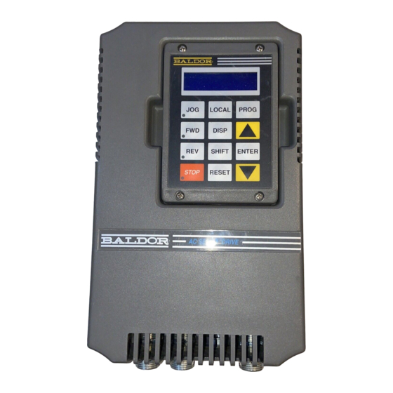
MN723H-10/95 11/28/95 1:19 AM Page 110 (Black plate) Appendix F Mounting Dimensions Size A Controls 7.120 7.20 Ø.25 (180.8mm) (182.9mm) (6.4mm) LOCAL PROG DISP SHIFT ENTER 11.50 STOP RESET 12.00 (292.1mm) (304.8mm) (6.4mm) 7.20 (182.9mm) 7.70 (195.6mm) 5-10 APPENDIX F... - Page 110 MN723H-10/95 11/28/95 1:19 AM Page 111 (Black plate) Size B Controls 9.25 Ø.28 TYP 7.120 (225.0mm) (7.1mm) (180.9mm) LOCAL PROG DISP SHIFT ENTER STOP RESET 14.65 15.40 (372.1mm) (391.2mm) 9.25 (7.1mm) (235.0mm) 10.00 (254.0mm) APPENDIX F 5-11...
- Page 111 MN723H-10/95 11/28/95 1:20 AM Page 112 (Black plate) Size C Controls 5-12 APPENDIX F...
- Page 112 MN723H-10/95 11/28/95 1:20 AM Page 113 (Black plate) Size D Controls 14.50 (368.5mm) 13.50 (343.0mm) LOCAL PROG DISP 25.00 SHIFT ENTER (635.0mm) STOP RESET 24.25 (616.0mm) 23.12 (587.0mm) (8.0mm) CUSTOMER AIR INLET POWER CONNECTIONS 10.00 (254.0mm) 10.20 (259.0mm) APPENDIX F 5-13...
- Page 113 MN723H-10/95 11/28/95 1:20 AM Page 114 (Black plate) Size E Controls 5-14 APPENDIX F...
- Page 114 MN723H-10/95 11/28/95 1:20 AM Page 115 (Black plate) Size E Control Through-Wall Mounting CONTROLLER ASSEMBLY 2 PLACES 4 PLACES 4 PLACES 4 PLACES CUSTOMER'S PANEL CUT FOAM TAPE AND APPLY TO PERIMETER OF CUTOUT TO SEAL INSTALLATION OF CONTROLLER 2 PLACES 2 PLACES THRU-WALL MOUNTING KIT...
- Page 115 MN723H-10/95 11/28/95 1:20 AM Page 116 (Black plate) Size F Controls THRU-WALL MOUNTING FLANGE SURFACE MOUNTING Ø .38 (9.5mm) FLANGE 3 PLACES 45.00 (1143mm) .38 (9.5mm) 6.24 6.76 3 PLACES (158mm) (172mm) 27.00 (686mm) 5-16 APPENDIX F...
- Page 116 MN723H-10/95 11/28/95 1:20 AM Page 117 (Black plate) Size F Control Through-Wall Mounting 34 PLACES CONTROLLER 34 PLACES ASSEMBLY CUSTOMER'S PANEL CUT FOAM TAPE AND APPLY TO PERIMETER OF CUTOUT TO SEAL INSTALLATION OF CONTROLLER THRU-WALL 2 PLACES MOUNTING KIT 2 PLACES INSTALLATION SEE PARTS LIST #0084001...
-
Page 117: Appendix G Parameter List
MN723H-10/95 11/28/95 1:20 AM Page 118 (Black plate) Appendix G Parameter List Level 1 Programming Blocks BLOCK TITLE DESCRIPTION AND SERIAL RANGE FACTORY PAGE USER MODE PARAMETER NUMBER PRESET SETTING PRESET SPEEDS PRESET SPEED #1 P1001 0 - MAX SPEED 0 RPM PRESET SPEED #2 P1002... - Page 118 MN723H-10/95 11/28/95 1:20 AM Page 119 (Black plate) BLOCK TITLE DESCRIPTION AND SERIAL RANGE FACTORY PAGE USER MODE PARAMETER NUMBER PRESET SETTING KEYPAD SETUP KEYPAD STOP KEY P1301 REMOTE ON, REMOTE REMOTE OFF KEYPAD STOP MODE P1302 COAST, REGEN REGEN KEYPAD RUN FWD P1303 ON, OFF...
- Page 119 MN723H-10/95 11/28/95 1:20 AM Page 120 (Black plate) BLOCK TITLE DESCRIPTION AND SERIAL RANGE FACTORY PAGE USER MODE PARAMETER NUMBER PRESET SETTING OUTPUT OPTO OUTPUT #1 P1501 AT SETPOINT READY ZERO SPEED AT SPEED OPTO OUTPUT #2 P1502 OVERLOAD ZERO KEYPAD CONTROL SPEED AT SET SPEED...
- Page 120 MN723H-10/95 11/28/95 1:21 AM Page 121 (Black plate) BLOCK TITLE DESCRIPTION AND SERIAL RANGE FACTORY PAGE USER MODE PARAMETER NUMBER PRESET SETTING BRUSHLESS RESOLVER ALIGN P1601 22.3 REF CALC 3-10 CONTROL SPEED FILTER P1602 CALC 3-10 FEEDBACK ALIGN P1603 FORWARD, REVERSE FORWARD 3-10 CURRENT PROP GAIN...
- Page 121 MN723H-10/95 11/28/95 1:21 AM Page 122 (Black plate) BLOCK TITLE DESCRIPTION AND SERIAL RANGE FACTORY PAGE USER MODE PARAMETER NUMBER PRESET SETTING CUSTOM UNITS DECIMAL PLACES P2101 3-12 VALUE AT SPEED P2102 0-65535 00000/ 01000 3-12 UNITS OF MEASURE P2103 SELECTION OF 9 **** CHARACTER SETS...
- Page 122 MN723H-10/95 11/28/95 1:21 AM Page 123 (Black plate) BLOCK TITLE DESCRIPTION AND SERIAL RANGE FACTORY PAGE USER MODE PARAMETER NUMBER PRESET SETTING MOTOR DATA MOTOR RATED AMPS P2501 0-999.9 FACTORY 3-15 MOTOR POLES P2502 2, 4, 6, 8 3-15 RESOLVER SPEEDS P2503 0 - 10 3-15...
- Page 123 MN723H-10/95 11/28/95 1:21 AM Page 124 (Black plate) BLOCK TITLE DESCRIPTION AND SERIAL RANGE FACTORY PAGE USER MODE PARAMETER NUMBER PRESET SETTING PROCESS PROCESS FEEDBACK P2701 POTENTIOMETER NONE CONTROL +/- 10 VOLTS +/- 5 VOLTS 4 - 20 mA 3-16 10V EXB 4 - 20 mA EXB 3 - 15 PSI EXB...
- Page 124 MN723H-10/95 11/28/95 1:21 AM Page 125 (Black plate) BLOCK TITLE DESCRIPTION AND SERIAL RANGE FACTORY PAGE USER MODE PARAMETER NUMBER PRESET SETTING 3-18 AUTO-TUNING CALC PRESET CALC YES, NO CMD OFFSET TRIM Trims out any voltage offsets on the differential command input (J1-4 & J1- 3-18 5).
- Page 125 MN723H-10/95 11/28/95 1:21 AM Page 126 (Black plate) 5-26 APPENDIX G...
- Page 126 MN723H-10/95 11/28/95 1:21 AM Page 127 (Black plate)
- Page 127 MN723H-10/95 11/28/95 1:21 AM Page 128 (Black plate) BALDOR ELECTRIC COMPANY P.O. Box 2400 Ft. Smith, AR 72902-2400 (501) 646-4711 FAX (501) 648-5792 © Baldor Electric Company Printed in USA MN723 10/95 C&J 5000...
Need help?
Do you have a question about the 23H series and is the answer not in the manual?
Questions and answers