
Related Manuals for Intel Edison


Summary of Contents for Intel Edison
- Page 1 Intel® Edison Breakout Board Hardware Guide January 2015 Revision 006 Document Number: 331190-006...
- Page 2 PARTICULAR PURPOSE, MERCHANTABILITY, OR INFRINGEMENT OF ANY PATENT, COPYRIGHT OR OTHER INTELLECTUAL PROPERTY RIGHT. A "Mission Critical Application" is any application in which failure of the Intel Product could result, directly or indirectly, in personal injury or death. SHOULD YOU PURCHASE OR USE INTEL’S PRODUCTS FOR ANY SUCH MISSION CRITICAL APPLICATION, YOU SHALL INDEMNIFY AND HOLD INTEL...
-
Page 3: Table Of Contents
Breakout board jumpers (top of board) ......................... 7 Figure 3 Breakout board jumpers (bottom of board) ........................ 8 Figure 4 Intel® Edison breakout board expansion board power distribution network ........... 11 Figure 5 Mechanical drawing ................................12 Figure 6 Inserting an Intel® Edison module to the breakout board ................. 13 Figure 7 Digikey sources.................................. - Page 4 Added details on the breakout board jumpers and USB connectivity. October 16, 2014 Added section on software recovery mode and information on the LEDs. November 14, 2014 Minor corrections. January 30, 2015 § Intel® Edison Breakout Board Hardware Guide January 2015 Document Number: 331190-006...
-
Page 5: Introduction
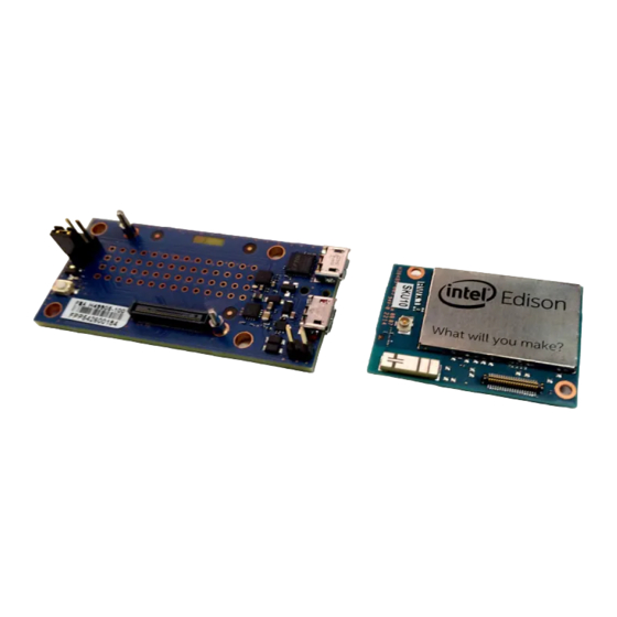
This document describes the Intel® Edison Breakout Board. The Intel® Edison Breakout Board is designed to expose the native 1.8 V I/O of the Intel® Edison module. The board consists of power supply, battery recharger, USB OTG power switch, UART to USB bridge, USB OTG port, and I/O header. -
Page 6: High-Level Functional Description
High-Level Functional Description High-Level Functional Description Figure 1 provides the block diagram for the Intel® Edison Breakout Board. Figure 1 Intel® Edison breakout board block diagram 7 to 15 V power supply 4.4 V power supply and battery recharger GPIO Intel®... -
Page 7: Intel® Edison Breakout Board Jumpers
J16 is a fully USB compatible, micro AB, OTG (power “on the go”) port. If you plug a micro A cable into this port, the Intel® Edison module will connect to a PC as the host; if you plug a micro B cable into this port, the Intel®... -
Page 8: Usb Interface
If you plug a USB micro A connector into it, the breakout board will function as a host. When you use the Intel® Edison Breakout Board as a host in this manner, you must supply external power via J21 or J22. The breakout board will convert that voltage to supply 5 V to the USB connector. -
Page 9: Intel® Edison Breakout Board Expansion Header
As outputs, the GPIOs can be individually cleared or set. They can be pre-programmed to either state when entering standby. Output drive is ±3 mA. Table 2 Intel® Edison breakout board expansion header signal list Description J17 - pin 1 GP182_PWM2 GPIO capable of PWM output. -
Page 10: Intel® Edison Breakout Board Expansion Power Supply
ORed with the USB VBUS rail. This power goes to a battery recharger IC, which limits the output voltage to 4.4 V. This voltage is in the safe range for the Edison module VSYS. The VSYS power range is 3.15 to 4.5 V. This allows the Intel®... -
Page 11: Boot Voltage Selection - Dcin Signal
The drawback to this design is that the linear supply power drop places a limit on the total power through the Intel® Edison board and the 3.3 and 1.8 V supplies. The power loss through the charger will be (4.4 to 5 V) • current. -
Page 12: Intel® Edison Breakout Board Buttons
• DS1 is the reset LED. (See Figure 2 for location.) It will turn on when the Intel® Edison processor is running. When the processor is in reset and asserting RESET_OUT# low, it will turn off. -
Page 13: Handling
When attaching an Intel® Edison module to breakout board, handle the Intel® Edison module by the PCB edges. Avoid holding or exerting pressure to the shields. To mate the Intel® Edison board to the breakout board, apply pressure directly above the connector and to the left corner. -
Page 14: Digikey Sources
DF40C(2.0)-70DS-0.4V(51) H11908TR-ND Tape and reel PJ-002BH-SMT-TR CP-002BHPJTR-ND Tape and reel Mini-breakout USB adapter cable Mini-breakout male header USB A female to Micro A male 10-00649 839-1105-ND 2x14 M20-9980745 952-1932-ND § Intel® Edison Breakout Board Hardware Guide January 2015 Document Number: 331190-006...
Need help?
Do you have a question about the Edison and is the answer not in the manual?
Questions and answers