Intel D865GVHZ Product Manual
Desktop board
Hide thumbs
Also See for D865GVHZ:
- Technical product specification (132 pages) ,
- Quick reference manual (18 pages)
Table of Contents
Advertisement
Advertisement
Table of Contents

Related Manuals for Intel D865GVHZ


Summary of Contents for Intel D865GVHZ
- Page 1 Intel Desktop Board ® D865GVHZ Product Guide C70847-001 Order Number:...
-
Page 2: Revision History
Intel products including liability or warranties relating to fitness for a particular purpose, merchantability, or infringement of any patent, copyright or other intellectual property right. Intel products are not intended for use in medical, life saving, or life sustaining applications. Intel may make changes to specifications and product descriptions at any time, without notice. -
Page 3: Intended Audience
Preface This Product Guide gives information about board layout, component installation, BIOS Setup menus, and regulatory requirements for Intel Intended Audience The Product Guide is intended for technically qualified personnel. Information Layout The chapters in this Product Guide are arranged as follows: Desktop Board Features: a summary of product features. - Page 4 Intel Desktop Board D865GVHZ Product Guide Notations Term Description Gigabyte (1,073,741,824 bytes) Kilobyte (1024 bytes) Megabyte (1,048,576 bytes) Mbit Megabit (1,048,576 bits) Megahertz (one million hertz) Third-party brands and names that are the property of their respective owners.
-
Page 5: Table Of Contents
Security Passwords ...17 Chassis Intrusion...18 Power Management Features ...18 ACPI...18 Power Connectors ...18 Fan Connectors...18 Fan Speed Control (Intel Suspend to RAM (Instantly Available PC Technology) ...19 Resume on Ring...19 Wake from USB...19 Wake from PS/2 Keyboard/Mouse...19 PME# Wakeup Support ...20 Speaker...20... - Page 6 Intel Desktop Board D865GVHZ Product Guide Installing and Removing a Processor ...26 Installing a Processor ...26 Installing the Processor Fan Heat Sink ...26 Connecting the Processor Fan Heat Sink Cable...27 Removing the Processor ...27 Installing and Removing Memory ...28 Installing DIMMs...29 Removing DIMMs...29...
- Page 7 Product Ecology Statements ...86 EMC Regulations ...87 Product Certification Markings (Board Level) ...88 Figures 1. Desktop Board D865GVHZ Components...11 2. Installing the I/O Shield ...24 3. Location of Mounting Screw Holes...25 4. Installing a Processor...26 5. Connecting the Processor Fan Heat Sink Cable to the Processor Fan Connector ...27 6.
- Page 8 Intel Desktop Board D865GVHZ Product Guide 10. BIOS Setup Program Function Keys...52 11. Maintenance Menu ...52 12. Main Menu...53 13. Advanced Menu...54 14. PCI Configuration Submenu ...55 15. Boot Configuration Submenu ...56 16. Peripheral Configuration Submenu ...57 17. ATA/IDE Configuration Submenu ...59 18.
-
Page 9: Desktop Board Features
1 Desktop Board Features This chapter describes the main features of Intel summarizes these features. Table 1. Feature Summary Form Factor MicroATX at 9.6-inches by 8.5-inches Processor Support for: • Intel • Intel • Two 184-pin, 2.5 V DDR SDRAM Dual Inline Memory Module (DIMM) sockets Main Memory •... -
Page 10: Supported Operating Systems
• Temperature sensing • Intel • Voltage sensing Related Links For more information about Intel Desktop Board D865GVHZ, including the Technical Product Specification (TPS), BIOS updates, and device drivers, go to: http://support.intel.com/support/motherboards/desktop/ Supported Operating Systems The desktop board supports the following operating systems: •... -
Page 11: Desktop Board Components
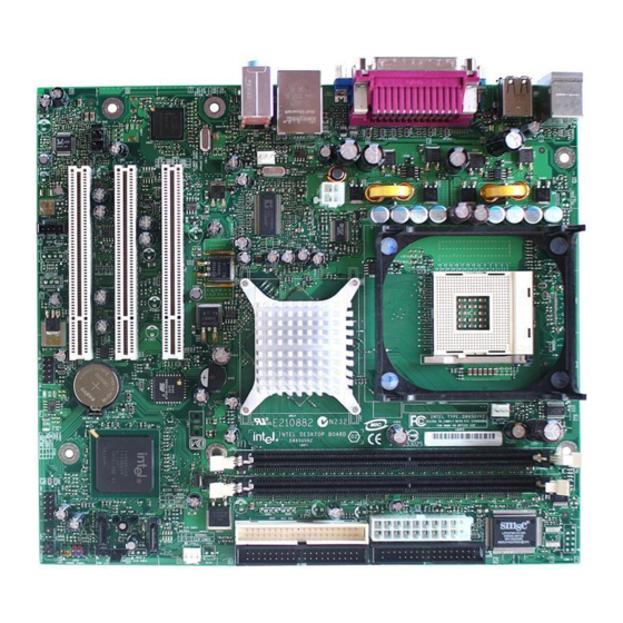
Desktop Board Components Figure 1 shows the approximate location of the major components on Desktop Board D865GVHZ. Figure 1. Desktop Board D865GVHZ Components USB 2.0 Desktop Board Features Line USB 2.0 OM17019... -
Page 12: Desktop Board Components
Intel Desktop Board D865GVHZ Product Guide Table 2. Desktop Board Components Label Description CD-ROM audio connector (ATAPI-style) Front panel audio header Rear chassis fan header 12 V processor core voltage connector Processor socket Processor fan header Intel 82865GV (GMCH) DIMM sockets... -
Page 13: Processor
CAUTION Failure to use an ATX12V power supply, or not connecting the 12 V processor core voltage power supply connector to Desktop Board D865GVHZ may result in damage to the desktop board and/or power supply. Desktop Board D865GVHZ supports a single Intel Pentium 4 processor or Intel Celeron processor. -
Page 14: Main Memory
Main Memory NOTE To be fully compliant with all applicable Intel board should be populated with DIMMs that support the Serial Presence Detect (SPD) data structure. If your memory modules do not support SPD, you will see a notification to this effect on the screen at power up. -
Page 15: Intel ® 865Gv Chipset
• Configurable EEPROM that contains the MAC address LAN Subsystem Software For LAN software and drivers, refer to the D865GVHZ link on Intel’s World Wide Web site at: http://support.intel.com/support/motherboards/desktop RJ-45 LAN Connector LEDs Two LEDs are built into the RJ-45 LAN connector. Table 4 describes the LED states when the board is powered up and the 10/100 Ethernet LAN subsystem is operating. -
Page 16: Input/Output (I/O) Controller
Intel Desktop Board D865GVHZ Product Guide Table 4. RJ-45 10/100 Ethernet LAN Connector LEDs LED Color LED State Green Yellow On (steady state) On (brighter and pulsing) Input/Output (I/O) Controller The super I/O controller features the following: • Low pin count (LPC) interface •... -
Page 17: Enhanced Ide Interface
Enhanced IDE Interface The ICH5’s IDE interface handles the exchange of information between the processor and peripheral devices like hard disks, CD-ROM drives, and Iomega Zip* drives inside the computer. The interface supports: • Up to four IDE devices (such as hard drives) •... -
Page 18: Chassis Intrusion
The desktop board has two power connectors. See Figure 10 on page 36 for the location of the power connectors. Fan Connectors The desktop board has two chassis fan connectors (Intel Precision Cooling Technology) and one processor fan connector. See Figure 10 on page 36 for the location of the fan connectors. ®... -
Page 19: Suspend To Ram (Instantly Available Pc Technology)
Related Link For more information about standby current requirements for these desktop boards, refer to the TPS by selecting the Technical Documentation link at: http://developer.intel.com/design/motherbd/ Resume on Ring The operation of Resume on Ring can be summarized as follows: •... -
Page 20: Pme# Wakeup Support
Intel Desktop Board D865GVHZ Product Guide PME# Wakeup Support When the PME# signal on the PCI bus is asserted, the computer wakes from an ACPI S1, S3, or S5 state. Speaker A speaker is mounted on the desktop board. The speaker provides audible error code (beep code) information during the Power-On Self-Test (POST). -
Page 21: Installing And Replacing Desktop Board Components
2 Installing and Replacing Desktop Board Components This chapter tells you how to: • Install the I/O shield • Install and remove the desktop board • Install and remove a processor and memory • Connect the IDE and/or Serial ATA cable •... -
Page 22: Installation Precautions
Installation Precautions When you install and test the Intel desktop board, observe all warnings and cautions in the installation instructions. To avoid injury, be careful of: •... -
Page 23: Chassis And Component Certifications
If the power supply and other modules or peripherals, as applicable, are not Class B EMC compliant before integration, then EMC testing is required on a representative sample of the newly completed computer. Chassis and Component Certifications Ensure that the chassis and certain components; such as the power supply, peripheral drives, wiring, and cables;... -
Page 24: Use Only For Intended Applications
Intel Desktop Board D865GVHZ Product Guide Use Only for Intended Applications All Intel desktop boards are evaluated as Information Technology Equipment (I.T.E.) for use in personal computers for installation in homes, offices, schools, computer rooms, and similar locations. The suitability of this product for other applications or environments, such as medical, industrial, alarm systems, test equipment, etc. -
Page 25: Installing And Removing The Desktop Board
Refer to Appendix B for regulatory requirements. Refer to your chassis manual for instructions on installing and removing the desktop board. Figure 3 shows the location of the six mounting screw holes for Desktop Board D865GVHZ. OM17021 Figure 3. Location of Mounting Screw Holes... -
Page 26: Installing And Removing A Processor
Desktop Board D865GVHZ has an integrated processor fan heat sink retention mechanism (RM). For instructions on how to install the processor fan heat sink to the integrated processor fan heat sink RM, refer to the boxed processor manual or the Intel World Wide Web site at: http://support.intel.com/support/processors/pentium4/intnotes478.htm Figure 4. -
Page 27: Connecting The Processor Fan Heat Sink Cable
Figure 5. Connecting the Processor Fan Heat Sink Cable to the Processor Fan Connector Removing the Processor For instruction on how to remove the processor fan heat sink and processor, refer to the processor installation manual or the Intel World Wide Web site at: http://support.intel.com/support/processors/pentium4/intnotes478.htm Installing and Replacing Desktop Board Components... -
Page 28: Installing And Removing Memory
Installing and Removing Memory CAUTION To be fully compliant with all applicable Intel SDRAM memory specification addendums, the board requires DIMMs that support the Serial Presence Detect (SPD) data structure. You can access the PC Serial Presence Detect Specification at: http://www.intel.com/technology/memory/pcsdram/spec/... -
Page 29: Installing Dimms
Installing DIMMs To install DIMMs, follow these steps: 1. Observe the precautions in “Before You Begin” on page 21. 2. Turn off all peripheral devices connected to the computer. Turn off the computer and disconnect the AC power cord. 3. Remove the computer’s cover and locate the DIMM sockets (see Figure 6). 4. -
Page 30: Connecting The Ide Cable
Observe the precautions in “Before You Begin” on page 21. • Attach the cable end with the single connector to the Intel desktop board (A). • Attach the cable end with the two closely spaced connectors to the drives (B). -
Page 31: Connecting The Serial Ata Cable
Installing and Replacing Desktop Board Components OM15238 OM17024 Figure 7. Connecting the IDE Cable Connecting the Serial ATA Cable The SATA cable (4-conductor) supports the Serial ATA protocol and connects a single drive to the desktop board. Either end of the cable can be connected to the SATA drive or the connector on the board (see Figure 8). -
Page 32: Connecting The Serial Ata Cable
Intel Desktop Board D865GVHZ Product Guide OM15238 OM17025 Figure 8. Connecting the Serial ATA Cable... -
Page 33: Connecting Internal Headers
Connecting Internal Headers Figure 9 shows the location of internal headers. Installing and Replacing Desktop Board Components Item Description Front panel audio Alternate power/sleep LED Front panel USB 2.0 USB 2.0 CD-ROM audio Figure 9. Internal Headers OM17026... -
Page 34: Connecting The Front Panel Header
Intel Desktop Board D865GVHZ Product Guide Connecting the Front Panel Header Before connecting the front panel header, observe the precautions in “Before You Begin” on page 21. Figure 9-C on page 33 shows the location of the front panel header. Table 5 shows the pin assignments for the front panel header. -
Page 35: Installing A Front Panel Audio Solution
Installing a Front Panel Audio Solution Figure 9-A shows the location of the front panel audio header. Table 7 shows the pin assignments for the front panel audio header. Table 7. Front Panel Audio Header Signal Names Signal Name AUD-MIC AUD-MIC-BIAS AUD-FPOUT-R HP-ON... -
Page 36: Connecting Hardware Control And Power Cables
Intel Desktop Board D865GVHZ Product Guide Connecting Hardware Control and Power Cables Figure 10 shows the location of the chassis intrusion and fan headers, and power connectors. Chassis rear fan Chassis intrusion connector Figure 10. Location of Hardware Control Headers and Power Connectors... -
Page 37: Connecting The Chassis Intrusion Cable
Connecting the Chassis Intrusion Cable Connect the chassis intrusion cable to the header shown in Figure 10. Connecting Fans Connect the processor’s fan heat sink cable to the processor fan header on the board. Connect chassis fan cables to the board fan headers. See Figure 10 for fan header locations. Connecting Power Supply Cables CAUTION Failure to use an ATX12V power supply, or not connecting the 12 V processor core voltage power... -
Page 38: Add-In Card And Peripheral Interface Connectors
Intel Desktop Board D865GVHZ Product Guide Add-In Card and Peripheral Interface Connectors Figure 11 shows the PCI bus add-in card and peripheral interface connectors for Desktop Board D865GVHZ. Item Description PCI bus add-in card connector 3 PCI bus add-in card connector 2 (SMBus routed) -
Page 39: Setting The Bios Configuration Jumper Block
Setting the BIOS Configuration Jumper Block CAUTION Always turn off the power and unplug the power cord from the computer before changing the jumper. Moving the jumper with the power on may result in unreliable computer operation. The location of the desktop board’s BIOS configuration jumper is shown in Figure 12. Figure 12. -
Page 40: Clearing Bios Passwords
Intel Desktop Board D865GVHZ Product Guide Clearing BIOS Passwords This procedure assumes that the board is installed in the computer and the BIOS configuration jumper block is set to normal mode. 1. Observe the precautions in “Before You Begin” on page 21. -
Page 41: Back Panel Connectors
Installing and Replacing Desktop Board Components Back Panel Connectors NOTE The line out connector, located on the back panel, is designed to power either headphones or amplified speakers only. Poor audio quality may occur if passive (non-amplified) speakers are connected to this output. Figure 13 shows the back panel connectors. -
Page 42: Replacing The Battery
Intel Desktop Board D865GVHZ Product Guide Replacing the Battery A coin-cell battery (CR2032) powers the real-time clock and CMOS memory. When the computer is not plugged into a wall socket, the battery has an estimated life of three years. When the computer is plugged in, the standby current from the power supply extends the life of the battery. - Page 43 Installing and Replacing Desktop Board Components AVVERTIMENTO Esiste il pericolo di un esplosione se la pila non viene sostituita in modo corretto. Utilizzare solo pile uguali o di tipo equivalente a quelle consigliate dal produttore. Per disfarsi delle pile usate, seguire le istruzioni del produttore.
- Page 44 Intel Desktop Board D865GVHZ Product Guide AWAS Risiko letupan wujud jika bateri digantikan dengan jenis yang tidak betul. Bateri sepatutnya dikitar semula jika boleh. Pelupusan bateri terpakai mestilah mematuhi peraturan alam sekitar tempatan. OSTRZEŻENIE Istnieje niebezpiecze�stwo wybuchu w przypadku zastosowania niew�a�ciwego typu baterii. Zu�yte baterie nale�y w miar�...
-
Page 45: Removing The Battery
To replace the battery, follow these steps: 1. Observe the precautions in “Before You Begin” (see page 21). 2. Turn off all peripheral devices connected to the computer. Disconnect the computer’s power cord from the AC power source (wall outlet or power adapter). 3. - Page 46 Intel Desktop Board D865GVHZ Product Guide...
-
Page 47: Updating The Bios
Updating the BIOS with the Intel Update Utility With the Intel Express BIOS Update utility you can update the system BIOS while in the Windows environment. The BIOS file is included in an automated update utility that combines the ®... -
Page 48: Updating The Bios With The Iflash Memory Update Utility
• Iflash Memory Update utility You can obtain the BIOS update file through your computer supplier or by navigating to the Desktop Board D865GVHZ page on the Intel World Wide Web site: http://support.intel.com/support/motherboards/desktop NOTE Review the instructions distributed with the update utility before attempting a BIOS update. -
Page 49: Recovering The Bios
Recovering the BIOS It is unlikely that anything will interrupt the BIOS update; however, if an interruption occurs, the BIOS could be damaged. The following steps explain how to recover the BIOS if an update fails. The following procedure uses recovery mode for the Setup program. See page 39 for more information on Setup modes. - Page 50 Intel Desktop Board D865GVHZ Product Guide...
-
Page 51: Using The Bios Setup Program
Service (BIS)* hardware credentials, and components configures extended configuration memory settings * For information about the BIS, refer to the Intel Web site at: http://developer.intel.com/design/security/index1.htm ® Desktop Board D865GVHZ Technical Product Specification or Advanced Security Power Configures Sets passwords... -
Page 52: Maintenance Menu
Intel Desktop Board D865GVHZ Product Guide Table 10 shows the function keys available for menu screens. Table 10. BIOS Setup Program Function Keys BIOS Setup Program Function Key < > or < > < > or < > <Tab> <Enter>... -
Page 53: Main Menu
• English (default) Language • Français System Time Hour, minute, and second Security Power Boot xxxxx10A.86A.xxxx.xxx Intel® Pentium® 4 [Enabled] X.XX GHz XXX MHz XXX MHz XXX KB XXX MB Dual Channel XXX MB (DDRYYY) Not Installed XXX MB (DDRYYY) -
Page 54: Advanced Menu
Intel Desktop Board D865GVHZ Product Guide Advanced Menu Main Advanced Security Setup Warning: Setting items on this screen to incorrect values may cause your system to malfunction! PCI Configuration Boot Configuration Peripheral Configuration IDE Configuration Diskette Configuration Event Log Configuration... -
Page 55: Pci Configuration Submenu
PCI Configuration Submenu Main Advanced Security PCI Configuration PCI Slot 1 IRQ Priority PCI Slot 2 IRQ Priority PCI Slot 3 IRQ Priority The submenu shown in Table 14 is used to configure the IRQ priority of PCI slots individually. Table 14. -
Page 56: Boot Configuration Submenu
Intel Desktop Board D865GVHZ Product Guide Boot Configuration Submenu Main Advanced Security Boot Configuration Plug & Play O/S Numlock ASF Support The submenu shown in Table 15 is used to set the Plug & Play options and the power-on state of the Numlock key. -
Page 57: Peripheral Configuration Submenu
Peripheral Configuration Submenu Main Advanced Security Peripheral Configuration Serial Port A Parallel Port Mode Audio Onboard LAN ASF Support This submenu shown in Table 16 is used for configuring computer peripherals. Table 16. Peripheral Configuration Submenu Feature Options • Disabled Serial Port A •... - Page 58 Intel Desktop Board D865GVHZ Product Guide Table 16. Peripheral Configuration Submenu (continued) Feature Options • Output only Mode • Bi-directional (default) • EPP • ECP • 378 (default) Base I/O Address (This feature is present • 278 only when Parallel Port is set to Enabled) •...
-
Page 59: Ata/Ide Configuration Submenu
• 3 Seconds • 6 Seconds • 9 Seconds • 12 Seconds • 15 Seconds • 21 Seconds • 30 Seconds NOTE: SATA hard drives are not supported on desktop board D865GVHZ. Power Boot Exit [Legacy] [PATA Pri and Sec] [Enabled]... -
Page 60: Pata Submenu
• Auto (default) • Auto (default) PIO Mode • 0 (Note) • 1 • 2 • 3 • 4 NOTE: SATA hard drives are not supported on desktop board D865GVHZ. Power Boot Exit Xxxxxxxx [Auto] [Auto] [Supported] 16 sectors Mode 4... - Page 61 Table 18. SATA and PATA Submenus (continued) Feature Options • Auto (default) DMA Mode • SWDMA 0 • SWDMA 1 • SWDMA 2 • MWDMA 0 • MWDMA 1 • MWDMA 2 • UDMA 0 • UDMA 1 • UDMA 2 •...
-
Page 62: Diskette Configuration Submenu
Intel Desktop Board D865GVHZ Product Guide Diskette Configuration Submenu Main Advanced Diskette Configuration Diskette Controller Floppy A Diskette Write Protect This submenu shown in Table 19 is used to configure the floppy drive. Table 19. Diskette Configuration Submenu Feature Options •... -
Page 63: Event Log Configuration Submenu
Event Log Configuration Submenu Main Advanced Event Log Configuration Event Log View Event Log Clear Event Log Event Logging ECC Event Logging Mark Events As Read The submenu shown in Table 20 is used to configure the event logging features. Table 20. -
Page 64: Video Configuration Submenu
Intel Desktop Board D865GVHZ Product Guide Video Configuration Submenu Main Advanced Video Configuration AGP Aperture Size Primary Video Adapter Frame Buffer Size The submenu shown in Table 21 is used to configure video features. Table 21. Video Configuration Submenu Feature Options •... -
Page 65: Usb Configuration Submenu
USB Configuration Submenu Main Advanced USB Configuration High-Speed USB Legacy USB Support USB 2.0 Legacy Support The submenu shown in Table 22 is used to configure USB features. Table 22. USB Configuration Submenu Feature High Speed USB Legacy USB Support USB 2.0 Legacy Support Security Power... -
Page 66: Chipset Configuration Submenu
Intel Desktop Board D865GVHZ Product Guide Chipset Configuration Submenu Main Advanced Chipset Configuration Setup Warning: Setting items on this screen to incorrect values may cause your system to malfunction! ISA Enable Bit PCI Latency Timer CSA Device Do you wish to continue? - Page 67 Table 23. Chipset Configuration Submenu (continued) Feature Options • Default (default) Extended Configuration • User Defined Graphics Core Frequency • Auto (default) • 266 MHz • 333-320 MHz • Auto (default) SDRAM Frequency • 266 MHz • 333 MHz • 400 MHz •...
-
Page 68: Fan Control Submenu
Intel Desktop Board D865GVHZ Product Guide Fan Control Submenu Main Advanced Fan Control Configuration Setup Warning: These options will not take effect until power has been completely removed from the system. saving the BIOS settings and turning the system off, unplug the power cord from the system and wait for at least 30 seconds before reapplying power and turning the system back on. -
Page 69: Security Menu
Security Menu Main Advanced Security Supervisor Password User Password Set Supervisor Password Set User Password Chassis Intrusion The menu shown in Table 25 is used to set passwords and security features. Table 25. Security Menu If no password entered previously: Feature Supervisor Password User Password... -
Page 70: Power Menu
Intel Desktop Board D865GVHZ Product Guide Power Menu Main Advanced ACPI After Power Failure The options below are not related to ACPI and may be ignored when shutting down using an ACPI OS. Wake on PCI PME The menu shown in Table 26 is used to set power management features. -
Page 71: Acpi Submenu
ACPI Submenu Main Advanced Security Advanced Configuration and Power Interface ACPI Suspend State Wake on LAN from S5 The submenu represented in Table 27 is for setting the ACPI features. Table 27. ACPI Submenu Feature Options • S1 State (default) ACPI Suspend Mode •... -
Page 72: Boot Menu
Intel Desktop Board D865GVHZ Product Guide Boot Menu Main Advanced Security Silent BOOT Intel ® Rapid BIOS Boot Scan User Flash Area PXE Boot to LAN USB Boot Boot Device Priority Hard Disk Drives Removable Devices ATAPI CD-ROM Drives The menu shown in Table 28 is used to set the boot features and the boot sequence. -
Page 73: Boot Device Priority Submenu
Boot Device Priority Submenu Main Advanced Security Boot Device Boot Device Boot Device The submenu represented in Table 29 is for setting boot devices priority. Table 29. Boot Device Priority Submenu Options Feature • Removable Device Boot Device • Hard Drive Boot Device •... -
Page 74: Hard Disk Drives Submenu
Intel Desktop Board D865GVHZ Product Guide Hard Disk Drives Submenu Main Advanced Security Drive Drive Drive Drive The submenu shown in Table 30 is for setting hard disk drives. Table 30. Hard Disk Drives Submenu Feature Options Hard Disk Drive... -
Page 75: Removable Devices Submenu
Removable Devices Submenu Main Advanced Security Drive The submenu in shown Table 31 is for setting removable devices. Table 31. Removable Devices Submenu Feature Options Removable Device Dependent on installed removable devices (Note) Note: This boot device submenu appears only if at least one boot device of this type is installed. This list will display up to four removable devices, the maximum number of removable devices supported by the BIOS. -
Page 76: Atapi Cd-Rom Drives
Intel Desktop Board D865GVHZ Product Guide ATAPI CD-ROM Drives Main Advanced Security 1st Drive Drive The submenu shown in Table 32 is for setting ATAPI CD-ROM drives. Table 32. ATAPI CD-ROM Drives Submenu Feature Options ATAPI CD-ROM Drive Dependent on installed... -
Page 77: Exit Menu
Exit Menu Main Advanced Security Exit Saving Changes Exit Discarding Changes Load Optimal Defaults Load Custom Defaults Save Custom Defaults Discard Changes The menu shown in Table 33 is used to exit the BIOS Setup program, saving changes, and loading and saving defaults. - Page 78 Intel Desktop Board D865GVHZ Product Guide...
-
Page 79: Desktop Board Resources
5 Desktop Board Resources Memory Map Table 34. System Memory Map Address Range (decimal) Address Range (hex) 1024 K - 2097152 K 100000 - 7FFFFFF 960 K - 1024 K F0000 - FFFFF 896 K - 960 K E0000 - EFFFF 800 K - 896 K C8000 - DFFFF 640 K - 800 K... -
Page 80: Interrupts
Intel Desktop Board D865GVHZ Product Guide Interrupts Table 36. Interrupts System Resource I/O channel check Reserved, interval timer Reserved, keyboard buffer full Reserved, cascade interrupt from slave PIC COM2* COM1* LPT2 (Plug and Play option) ** Floppy drive controller LPT1*... -
Page 81: A Error Messages And Indicators
A Error Messages and Indicators Desktop Board D865GVHZ reports POST errors in two ways: • By sounding a beep code • By displaying an error message on the monitor BIOS Beep Codes The BIOS beep codes are listed in Table 37. The BIOS also issues a beep code (one long tone followed by two short tones) during POST if the video configuration fails (a faulty video card or no card installed) or if an external ROM module does not properly checksum to zero. -
Page 82: Bios Error Messages
Intel Desktop Board D865GVHZ Product Guide BIOS Error Messages When a recoverable error occurs during the POST, the BIOS displays an error message describing the problem. Table 38. BIOS Error Messages Error Message GA20 Error Pri Master HDD Error Pri Slave HDD Error... - Page 83 Table 38. BIOS Error Messages (continued) Error Message Memory Size Decreased Memory Size Increased Memory Size Changed No Boot Device Available Off Board Parity Error On Board Parity Error Parity Error NVRAM / CMOS / PASSWORD cleared by Jumper <CTRL_N> Pressed Error Messages and Indicators Explanation Memory size has decreased since the last boot.
- Page 84 Intel Desktop Board D865GVHZ Product Guide...
-
Page 85: B Regulatory Compliance
Product Ecology statements • Electromagnetic Compatibility (EMC) regulations • Product certification markings Safety Regulations Desktop Board D865GVHZ complies with the safety regulations stated in Table 39 when correctly installed in a compatible host system. Table 39. Safety Regulations Regulation UL 60950-1:2003/ CSA C22.2 No. -
Page 86: Product Ecology Statements
Recycling Considerations Intel encourages its customers to recycle its products and their components (e.g., batteries, circuit boards, plastic enclosures, etc.) whenever possible. In the U.S., a list of recyclers in your area can be found at: http://www.eiae.org... -
Page 87: Emc Regulations
EMC Regulations Desktop Board D865GVHZ complies with the EMC regulations stated in Table 40 when correctly installed in a compatible host system. Table 40. EMC Regulations Regulation FCC Class B ICES-003 (Class B) EN55022: 1998 (Class B) EN55024: 1998 AS/NZS 3548 (Class B) -
Page 88: Product Certification Markings (Board Level)
CE mark should also be on the shipping container. Australian Communications Authority (ACA) C-tick mark. Includes adjacent Intel supplier code number, N-232. The C-tick mark should also be on the shipping container. Printed wiring board manufacturer’s recognition mark: consists of a unique UL recognized manufacturer’s logo, along with a flammability rating (solder side).
Need help?
Do you have a question about the D865GVHZ and is the answer not in the manual?
Questions and answers