
Related Manuals for Lamtec VMS Series


Summary of Contents for Lamtec VMS Series
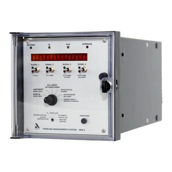
- Page 1 Manual Fuel/Air Ratio Control System VMS Sensors and Systems for Combustion Technology www.lamtec.de...
-
Page 3: Table Of Contents
Table of Contents Table of Contents General Information ............7 Validity of these Instructions. - Page 4 Table of Contents Firing Rate Controller (optional) ..........24 Operation .
- Page 5 Table of Contents 6.6.4 Operating Control and Displays........51 6.6.4.1 Mode Switching .
- Page 6 10.4 Changing Control Drives / Potentiometers........115 10.4.1 How to replace a motor with LAMTEC pre-calibration....115 10.4.2 How to Replace a Complete Control Drive .
- Page 7 Table of Contents 10.9.2 Selection of a Suitable R. P. M. Sensor ......131 10.10 Connection Diagram Relay Modules .
-
Page 8: General Information
The software-related information relates to software version v5.8. The software version can be found on the label of the programme EPROM. In case of doubt ask the LAMTEC Service - phone: +49 (0)6227 6052-33 or email: support @lamtec.de If you use another software version as the version mentioned above, some of the described functions may not be available or some function which are available with your software version may not be described in this manual. -
Page 9: How To Use These Instructions
If the fault still occurs, it is probably a plant-specific fault. NOTICE You can download the up-to-date version of these instructions from http://www.lamtec.de as a PDF File. You will find the version number at the backside of this document:... -
Page 10: Purpose
General Information Purpose 1.3.1 Purpose Intended purpose VMS 4/VMS 5 The VMS 4 as well as VMS 5 is a control unit for combustion system. Brief description The VMS 4 adjusts up to four control elements as a function of a control variable (generally the burner firing rate) according to freely programmable curves. -
Page 11: Purpose Internal Firing Rate Controller
General Information The operating states are predefined in the VMS through potential-free contacts – Burner on – Control enabling – Pre-purge – Recirculation enabling – Flame signal – Fuel selection The unit is of error-proof construction. 1.3.2 Purpose Internal Firing Rate Controller This software option enables the calculating of the burner's required firing rate setting contin- uously for a specified setpoint value (referred e.g. -
Page 12: For Your Safety
For Your Safety For Your Safety The following symbols are used in this document to draw the user's attention to important safe- ty information. They are located at points where the information is required. It is essential that the safety information is observed and followed, and that applies particularly to the warnings. DANGER! This draws the user's attention to imminent danger. -
Page 13: Operation
Operation Operation Digital Inputs Digital inputs VMS For the VMS to work in accordance with the requirements of the combustion plant, the status signal of the plant must be reported to the VMS. These are: – Burner start-up – Control release –... -
Page 14: Range Limits
Operation Correction is active. The controller remains in the base firing rate position until a control ena- bling signal (terminal 4) is given. Once control is released, the VMS tracks the externally ap- plied firing rate. A current signal proportional to the position of the fuel/air ratio control is emitted as internal firing rate (not on VMS 5). -
Page 15: Flying Curve Change
Operation Flying Curve Change If the select signal for the curve sets is changed whilst in operation, the VMS goes to fault 351. With this option, however, it allows changing from one curve set to another. The settings change abruptly. The band monitorings are replaced for a period of 30 seconds by running direction monitoring. -
Page 16: Pre-Purge Limit
Operation 3.13 Pre-purge Limit Normally during pre-purge each control element runs as far as it’s uppermost stop. Now, by parameters, a limit can be set for each channel that is not exceeded during pre-purge. 3.14 Energy-saving Mode for Scrolling Text Display The brightness of the display can be adjusted to the ambient light conditions by parameters. -
Page 17: Settings
Settings Settings Inputs 4.1.1 Significance of ID Number The ID number comprises of 8 characters, e.g. 664 V 0010. The two figures before the letter denote the unit, in this case a VMS 4. The letter denotes whether the unit is a VMS or a . The penultimate figure provides information on the unit hardware. -
Page 18: Configuration Number
Settings 4.1.4 Configuration Number The configuration number is a 15-digit number, constructed according to a fixed code. K = Channel assignment f = Input voltage a, b, or d = Feedback, correction and firing rate Y = 1 Recirculation X = 1 ... -
Page 19: Conditions On Delivery
Settings Conditions On Delivery All units are set according to the order. Settings not evident from the ID number or configura- tion number must be indicated separately. In particular: Outputs – whether continuous or three-point step – whether 0…10 V, 0/4 … 20 mA –... -
Page 20: Configuration Cards (Examples)
Settings 4.2.2 Configuration Cards (Examples) Fig. 4-2 Example: Configuration card 4.2.3 Processor Card Fig. 4-3 Processor card NOTICE Continuous channels must have all be fitted with additional cards from channel 1 onwards... -
Page 21: Power Supply Card
Settings 4.2.4 Power Supply Card Fig. 4-4 Power supply card 4.2.5 Plug-in P.C.Card for Continuous Output The standard control outputs are three-point step (except for a possible 5-channel. This is always continuous). Each TPS output can be reconfigured to make it continuous by plugging in an additional card. -
Page 22: Parameter
Access to all parameters that are not fixed on the basis of standards and technical regulations. • Production levels (Level 3 and 4) Access to all parameters (only possible through LAMTEC) Each parameter level is protected by its own checksum. This checksum serves to show that no changes have been made. -
Page 23: Password Entry
Settings 4.3.3 Password Entry Switch (1) to STATUS Push switch (4), channel 2 and 3, up and at the same time push channel 4 down the input field for the password appears on the dis- play. Set the appropriate password via the switch (4). Select accept key (3) Switch (2) to parameter setting ... -
Page 24: Changing Parameters
Settings 4.3.5 Changing Parameters Select the required parameter with Channel 3 key Change its value with Channel 4 key -The values are accepted immediately without further confirmation An explanatory text for the parameters can be called up by pressing the Enter key (3) NOTICE For larger values, changes can be in x100 steps with Channel 1 key and in x10 steps with Channel 2 key. -
Page 25: Firing Rate Controller (Optional)
Firing Rate Controller (optional) Firing Rate Controller (optional) Operation 5.1.1 Enter Setpoint of Firing Rate Controller Up to software version A3i1023, you can change the setpoint through parameter setting. From software version A3i1023 onwards, you can change the setpoint of the firing rate con- troller. -
Page 26: Control By Atmospheric Condition
Firing Rate Controller (optional) 5.1.3 Control by Atmospheric Condition If the burner firing rate controller is configured as "controlled by atmospheric conditions" the setpoint value can be shifted between the parameterised setpoint minimum and setpoint max- imum by connecting another PT 100 temperature sensor. When utilising control by atmos- pheric conditions, the outside temperature is a component of setpoint calculation. -
Page 27: Start-Up Sequence
Firing Rate Controller (optional) 5.1.5 Start-up Sequence The firing rate controller has a startup circuit, in order to slow down the burner's start firing rate. The startup circuit is run during each new burner start. The internal firing rate is held at a value P 792 adjustable by the user, for as long as the boiler is cold (actual value is below a user- adjustable limit, P 791). -
Page 28: Thermostat And Control Range
Firing Rate Controller (optional) 5.1.6 Thermostat and Control Range The thermostat function switches the burner on and off on the basis of the temperature and/ or pressure value, but only when burner is released by the start signal. The control range is formed by entering the controller setpoint value and the parameters P 802 (switch-on point), P803 (upper control range) and P 804 (burner OFF). -
Page 29: Manual Control
Firing Rate Controller (optional) 5.1.7 Manual Control The output controller’s firing rate specification can be overwritten by turning the selector switch (2) to LOAD RATING (firing rate) and pressing the Channel 1 switch (4) upwards. This manual firing rate control is cancelled by pressing the Channel 2 switch (4) downwards. -
Page 30: Control Range
Firing Rate Controller (optional) 5.2.3 Control Range The control range lies around the setpoint. The content of the "Burner on" parameter is sub- tracted from the setpoint value to form the switch-on value. The value of the "Upper control range" parameter (P 803) is added to the setpoint value to form the upper limit of the control range. - Page 31 Firing Rate Controller (optional) I > → faster approximation to the setpoint danger of overshooting! • D term The derivative term is calculated from the variation of the actual values. It has acceleration and respectively slowing effects. In practice the adjustment of the PID-controller is specified to each controlled system. With the characteristics of the controlled system you try to deduce acceptable data, i.e.
- Page 32 Firing Rate Controller (optional) Characteristic Control Process Control Mode Start-up Procedure I term smaller increase of attenu- less reaction, less ten- slower start-up ation dency to oscillate Fig. 5-6 Controller operation with I-term too high Characteristic Control Process Control Mode Start-up Procedure D term higher decrease of atten-...
-
Page 33: Commissioning
Commissioning Commissioning Before Commissioning 6.1.1 Setting the Limit Switches of the Motors As soon as the VMS is supplied with voltage, it attempts to drive the actuator motors to the lower limit of the factory set curve. If the end-bearing's limit switches are not properly adjusted for this, the motor may hit the actuator's mechanical stop WARNING! This may damage the motor or the valve. -
Page 34: Significance Of Digital Display
Commissioning On a 4 channel unit: Turn selector switch (1) to DIGITAL INPUTS On a 5 channel unit: Turn selector switch (1) to channel 5 display select acceptance (3) the display shows status of the digital inputs – = input not activated ... -
Page 35: Adjusting Control Elements
Commissioning Adjusting Control Elements 6.4.1 Operation Of Control Elements For Potentiometer Adjustment - Limit Switch Settings NOTICE “Setting” mode permits direct access to the control elements. It is therefore essential to follow the safety rules specified by the burner manufacturer! NOTICE Adjust the control elements only when the system is stationary. -
Page 36: Programming Of Curves
Commissioning Potentiometer adjustment values (approximate) Lower stop Upper stop * 5 kΩ 1 kΩ provided that potentiometer r.p.m. range is fully utilised Programming of Curves 6.5.1 Programming of Fuel/Air Ratio Control NOTICE Final programming of the unit with the burner stationary can only be done when it is certain that all feedback signals are present in the same way as when the burner is in operation (e.g. -
Page 37: Entirely New Curve - Clear Memory
Commissioning 6.5.2 Entirely New Curve - Clear Memory Turn selector switch (1) to SETPOINT Turn selector switch (2) to CLEAR MEMORY ’SL’ appears in centre of display Press ENTER (3): ’cleared’ appears on display NOTICE When programming the ignition firing rate point for the first time, it is recommended that the VMS be initially started. -
Page 38: Programming While The Burner Is Running
Commissioning 6.5.4 Programming While The Burner Is Running (pre-purge has been carried out previously without programmed point) Start burner and wait for pre-purge period. Turn selector switch (1) to SETPOINT Switch (4) up or down until system is optimally adjusted at ignition firing rate point. -
Page 39: Programming While The Burner Is Stationary
Commissioning 6.5.5 Programming While The Burner Is Stationary NOTICE The monitoring values may clearly deviate from the values of the main processor, depending on the configuration (redundant signals or not). It is essential that the actual value matches the setpoint value of the respective processors, not the correspondance of values between the processors. -
Page 40: Programming 2 Nd To 20 Th Point
Commissioning 6.5.6 Programming 2 to 20 Point Set selector switch (1) to "firing rate rating”. Run to desired firing rate rating using channel 1 switch. Set selector switch (1) to "setpoint” Switch (4) up or down until system is optimally adjusted at instantaneous firing rate On VMS 5: Selector switch (1) to "Channel 5 display"... -
Page 41: Programming Last Top Point
Commissioning 6.5.7 Programming Last Top Point Selector switch (1) to "Firing rate rating” Run to top firing rate rating 999 on the display (corresponds to 20 mA as firing rate input) NOTICE It is essential to run to the highest firing rate that can be preset by the firing rate control unit in operation, otherwise the fuel/air ratio control cannot completely follow the firing rate control unit. -
Page 42: Check Monitoring Values
Commissioning 6.5.9 Check Monitoring Values Turn selector switch (2) to MONITORING DISPLAY – The display switches to the values of the monitoring section Turn selector switch (1) to FIRING RATE RATING (firing rate) Move to programmed firing-rate rating Turn selector switch to SETPOINT or ACTUAL VALUE FEEDBACK NOTICE The monitoring values may clearly deviate from the values of the main processor, depending on the configuration (redundant signals or not). -
Page 43: Adding Points
Commissioning 6.5.10 Adding Points Should there be a previously saved curve that does not contain twenty points, additional points may be added. Turn selector switch (2) to SETTINGS Turn selector switch (1) to FIRING RATE RATING (fir- ing rate) Run to desired firing rate If the display shows a flashing number after the firing- rate rating, instead of adding a new point an old one is overwritten. -
Page 44: Change Curve Point
Commissioning 6.5.11 Change Curve Point Turn selector switch (2) to SETTINGS Turn selector switch (1) to LOAD RATING (firing rate) Using switch (4) channel 1, run to firing rate of the setpoints which are to be changed. Recognisable by flashing digits after firing rate, e.g. 700 (8) The display must show a digit or ’Z’... -
Page 45: O 2 Trim
Commissioning Trim 6.6.1 Automatic Function Monitoring During Operation 6.6.1.1 Adjusted The Integrated O2 Controller (Optional) This section explains only the operating steps needed to input the O curve. Further informa- tion on O controller is contained in the publication DLT 5002 Commissioning Supplement for the Optional ’Integrated O Controller’. -
Page 46: O 2 Limit Curve
Commissioning 6.6.1.4 O Limit Curve You can set the monitoring bands’ parameters for 2 fuels, oil/gas, as a function of fuel. The permitted deviation is calculated as a percentage of the setpoint. You can specify two separate percentage values for base firing rate and full firing rate. The section between is interpolated linearly. -
Page 47: Dynamic Probe Test
Commissioning 6.6.1.5 Dynamic Probe Test The VMS monitors the measured O value for changes during operation. If a fluctuation no higher than 0.2 O vol.% is detected over a period of 10 minutes, a state of excess air is en- forced by changing the fuel/air mixture. -
Page 48: Correction Output Monitoring
Commissioning 6.6.1.7 Correction Output Monitoring The controlling strategies employed were specially developed and optimised for the circum- stances prevailing in combustion facilities: - Frequent output changes - long lag time During burner start-up, the O controller remains on standby until it is ensured that plausible measured values are being displayed. -
Page 49: Control Strategy
Commissioning 6.6.2 Control Strategy 6.6.2.1 With Pre-setting For Firing Rate Changes trim by means of a comparison between target and actual values is only performed if no output change (firing rate change) takes place (’internal firing rate’ static). After a preceding firing rate change, an target/actual value comparison is performed and an actuation step trig- gered only after expiry of the set lag time (parameters 898 and 900). -
Page 50: Extended Control Strategy (Air Shortage)
Commissioning Parameter 896 can be used to select whether the pre-setting is always (at each firing rate change) to be activated (factory setting Standard 1), or not activated (content 2). Furthermore, the updating too can be turned off. It is then possible to select whether, at firing rate changes, the neutral correction value or the ’Base value without controller’... -
Page 51: Connecting The O 2 Measurement Device
< 15 sec may be connected. Release of the analogue interface is only possible at the factory (type 663R0030).In case of doubt, please contact LAMTEC. Range compensation via parameters P 919 and P 920 Factory setting: 4 ... 20 mA 0 ... 25,0 vol. % O... -
Page 52: Operating Control And Displays
Commissioning 6.6.4 Operating Control and Displays 6.6.4.1 Mode Switching Turn selector switch (1) to STATUS. Channel key 3 in upward position the display shows O trim. Turn selector switch to STATUS position the display shows O actual value and O target value. -
Page 53: Calling Up O Trim Text Messages
Commissioning 6.6.4.2 Calling up O Trim Text Messages Switch display to O -trim. Turn selection switch (1) to STATUS, Push channel key 3 (4) upwards Press the ENTER key (3) to call up the indication. Back → press ENTER key again (3), or turn selection switch (1) to another position. -
Page 54: Commissioning
Commissioning 6.6.5 Commissioning 6.6.5.1 Correction Output Monitoring The controlling strategies employed were specially developed and optimised for the circum- stances prevailing in combustion facilities: - Frequent output changes - long lag time During burner start-up, the O controller remains on standby until it is ensured that plausible measured values are being displayed. - Page 55 Commissioning The O values calculated during burner adjustment are input and stored as follows, regardless of whether the burner is off or in operation. The O target values can be input arbitrarily. It is not necessary to observe any particular sequence. Turn selector switch (2) to O TRIM Delete the whole O...
-
Page 56: Changing The O2 Setpoint Curve
Commissioning 6.6.5.3 Changing the O2 setpoint curve Vorgehensweise wie unter Eingabe von O -Sollwert beschrieben. Kanaltaster 4 (2) jedoch anstelle nach oben nach unten drücken. Turn selector switch (1) to Status 6.6.5.4 Calling up the Set Correction Mode Turn selector switch (1) to STATUS Press ENTER (3) ... -
Page 57: Lag Time (Parameters 898 / 900)
Commissioning NOTICE The P-factor (proportionality factor, parameter 899) is specified by the parameter setting. The new correction is obtained from two input quantities, deviation and P-factor. This would be transmitted to the VMS as an output. The procedure is repeated after lag time's expiry. If the internal firing rate has changed during this time, the O controller exits this routine. -
Page 58: Setting A Base Value For "Deactivated Controller" And "Air Shortage
Commissioning NOTICE It is possible to achieve optimisation by manipulating P-factor (parameter 899) and dead time (parameters 898 and 900), that inter alia also depends on the installation's properties; e.g. one may set a somewhat shorter dead time if the P-factor is reduced at the same time. Recommendation: Set a slightly longer regulation cycle and smaller P-factor ... -
Page 59: What Additional Modes Mean
Commissioning 6.6.5.10 What Additional Modes mean trim on standby (during burner start-up), or trim temporarily switched off by parameters 914 and 915, depending on firing rate. trim active trim temporarily deactivated (air shortage, probe dynamics etc). trim deactivated (in fault), e.g. test routines failed during burner start-up, dynamic test nega- tive, O trim temporarily deactivated for over 1... -
Page 60: How To Reset Od
Commissioning 6.6.5.11 How to Reset od Manually: Turn selector switch to ’O TRIM’ mode. Press the key ENTER and call up error text. Push key 3 (2) upwards WARNING! Before deleting a fault, it is absolutely necessary to call up the fault text! Automatically: faults will be reset automatically at every burner start-up. -
Page 61: Correction
Commissioning Correction 6.7.1 Set Correction Input Correction signal 1: terminal 27 and 29 Correction signal 2: terminal 33 and 34 The following settings can be set by parameters in service level (level 2) Current signal: Current input 1 0 … 20 or 4 … 20 mA Current input 2 0 …... - Page 62 Commissioning Spread factor > 10 Increase > 1.0 Mode +60..-40 Input 0%...100% Neutral value If the correction is applied to a fuel actuator, the effect is reversed so that 0% corresponds to the smallest target value. By using the spread factor held in parameter 433 - Commissioning level - the correction effect can also be weighted across the burner's output.
- Page 63 Commissioning Spread factor > 10 Increase > 1.0 Mode -60..+40 Input 0%...100% Neutral value Factory settings: spread factor 10 1.0, i.e. no weighting spread factor >10 the correction increases with rising burner output; spread factor <10 the correction decreases with rising burner output; WARNING! When applying O corrections, make sure that the combustion limits are observed even with...
-
Page 64: Correction Type 2
Commissioning 6.7.3 Correction Type 2 NOTICE This is useful only if curve rises continuously! WARNING! Do not use if parts of the curve are horizontal. WARNING! When applying O corrections, make sure that the combustion limits are observed even with the maximum correction applied (100%). -
Page 65: Correctional Range
Commissioning 6.7.4 Correctional Range 6.7.4.1 Correction Range Settings Use parameter 517 to adjust the correction range from 0 to 999. Example: Ccorrection mode P 437 for O trim is +60/-40 CO control is +50/-50. Correction range P 517 is 100 (digit). This means: The adjusting range of the setpoint which can be modified in correc- tion mode should be between +60 (digit) and -40 (digit). - Page 66 Commissioning Examples and illustrations: Correction mode + 60 % ... - 40 % (recommended for air correction) + 60 % corresponds to correction input value 0 - 40 % corresponds to correction input value 1000 Neutral value 600 60% Correction mode - 60 % …...
-
Page 67: Correction Modes
Commissioning 6.7.5 Correction Modes Correction for air actuator Correction for fuel actuator (valve/r.p.m.) Base setting Base setting + 50 % ___ - 50 % 50 % - 50 % ___ + 50 % 50 % + 60 % ___ - 40 % 60 % - 60 % ___ + 40 % 40 %... -
Page 68: Shut-Off Limits
Commissioning Shut-off Limits 6.8.1 Run to Shut-off Limits The VMS tolerance which was showed by every control system affects the positioning accu- racy. These tolerances can be influenced by parameter settings. When the combustion plant is adjusted, it has to be ensured that the flame burns safe and stable under these tolerances. -
Page 69: Check Shut-Off Limits On Tps Output Of Vms
Commissioning 6.8.2 Check Shut-Off Limits on TPS Output of VMS Switch (1) to FIRING RATE Run to firing rate point to be checked Wait until the system has run through that point Switch (2) to SETTING Adjust setpoint value (4) of the three-point step channel in air deficiency direction (for dead band setting, see parameters 62-76) Check combustion... -
Page 70: Check Shut-Off Limits On Vms Continuous Output
Commissioning 6.8.3 Check Shut-Off Limits on VMS Continuous Output This test is necessary with the use of continuous actuators and with r.p.m.control without the use of CO/O control affecting these r.p.m. The usage of O trim can be abandoned, if the excess air of deactivated O trim is higher than the setpoint. -
Page 71: Checking O 2 Influence
Commissioning 6.8.4 Checking O Influence NOTICE If the system is not equipped with an additional O - or CO-monitor, it has to be ensured that the combustion boundary values are kept at maximum adjacent correctional influence. The correction value can be altered as follows in order to set the correction range and to check the combustion boundary values. -
Page 72: Tolerance Limit In Direction Air Deficiency
Commissioning 6.8.5 Tolerance Limit in Direction Air Deficiency To be able to perform the test, the parameter values in the air deficiency direction should be known. WARNING! If the default setting for dead bands and monitoring bands have changed during commission- ing, this must be documented clearly. -
Page 73: Protocol Example
Commissioning 6.8.6 Protocol Example Date: Serial No.: Installation: Operating mode: Tolerance on air shortage side: Channel Functions Dead band Monitoring Band Band shift 32 /34 62 / 67 Channel 1 33 / 43 63 / 73 Channel 2 Channel 3 34 / 35 64 / 74 Channel 4... -
Page 74: Tips And Tricks
Tips and Tricks Tips and Tricks Programming 1st Point (Ignition Firing Rate Point) Programme the first point (ignition firing rate point) If no separate fuel/air ratio is to be set for the ignition point (selectable via parameter 4 = 0 or 2), proceed as described here. -
Page 75: Programming While The Burner Is Running
Tips and Tricks Turn selector switch (1) to SETPOINT Switch (4) up or down until system is optimally adjusted at ignition firing-rate point control element reacts display changes Turn selector switch (1) to ACTUAL VALUE FEED- BACK Value of the external feedback (with continuous out- put) is displayed ... -
Page 76: Programming While The Burner Is Stationary
Tips and Tricks Programming While The Burner Is Stationary Press the ENTER (3) key. The display shows ignition point 1. Reversing the Programming If programming has already started and these values should not be saved, but the old curve should be re-activated instead, then do the following: Turn selector switch (2) to CLEAR MEMORY Turn selector switch (1) to SETPOINT... -
Page 77: Adjusting Firing Rate Individually
Tips and Tricks Adjusting Firing Rate Individually Adjusting firing rate ratings individually when firing rate points are to be adjusted without pro- gramming a complete curve. When adjusting individual points it is normally only possible to freely adjust the setpoint val- ues. -
Page 78: Enter Set Point Values
Tips and Tricks Enter Set Point Values Selector switch (2) to "Setting” Run to desired setpoint from above if accidentally running below this point Run above setpoint and re-approach from above 7.10 Entering the Highest Setpoint Selector switch (2) to "Setting” Run to desired setpoint from below If accidentally running below this point ... -
Page 79: Entering The Fuel/Air Ratio Control With The Burner Stationary
Tips and Tricks 7.14 Entering the Fuel/Air Ratio Control With The Burner Stationary Disconnect ’Burner On’ signal (terminal 2) so that burner does not start Control the fan manually (e.g. Bridge terminal 81 and terminal 89 on relay R16) CAUTION! Danger of electrical shock! As a result, terminal 92 also receives a voltage Enter curve. -
Page 80: System Operation
System Operation System Operation Mode Display 8.1.1 Mode Abbreviations Used → SWITCH-ON SEQUENCE → READY ZÜ → IGNITION POSITION → SETTING/IGNITION → BASE FIRING RATE → SETTING/BASE FIRING RATE → POST-PURGE → → SETTING → CLEAR MEMORY → SETTING/PRE-PURGE → SETTING/CONTROL →... -
Page 81: O2 Trim Modes
System Operation indicates that although the mode selector switch is on SETTING it is nev- ertheless performing the pre-purge routine. These is a signal on terminal If the selector switch is on SETTING and there is a ’signal on terminal 3’, nevertheless the VMS maintains its control function. -
Page 82: Proceed With Programming
System Operation NOTICE This mode allows the electronic fuel/air ratio control to run within curve sections already en- tered and thereby facilitates setting. If the firing rate drops by 40 points, the VMS skips to ES mode, thereby controlling the outputs automatically. -
Page 83: Check Sums - Hours Of Operation
CRC 16 level 0: adjustable without password 1: adjustable by person commissioning 2: adjustable by the burner manufacturer or the boiler manufacturer 3: adjustable by LAMTEC only 4: adjustable by LAMTEC only oil safety time in seconds oil safety time in seconds... -
Page 84: Calling Up The Hour Counter
System Operation 8.2.2 Calling up the Hour Counter Turn selector switch (1) to SETPOINT the display shows a moving text with the following content: – total running hours – running hours on curve set 1 – starts on curve set 1 –... -
Page 85: Messages / Faults
System Operation Messages / Faults 8.3.1 What Happens if There is a Fault? NOTICE If the processor detects a fault, it runs the outputs in the programmed direction, e.g. air on, fuel off, re-circulation closed. The fuel solenoid valves close. The fault signal relay pulls on with a few seconds delay. Auto- matic restarting may be possible, depending on the nature of the fault. -
Page 86: Recalling Fault History
System Operation 8.3.4 Recalling Fault History NOTICE The VMS stores the last 10 faults with the associated running time meter values Turn selector switch (1) to STATUS the display shows the actual status Channel 1 switch (4) up the display shows the latest fault code and the firing rate values from the moment when the fault occurs Press ENTER (3) -
Page 87: Air Deficiency Failure
System Operation 8.3.6 Air Deficiency Failure If the O actual value is significantly smaller than the O setpoint value (below the second monitoring band) and corrective actions by the VMS cannot clear this error, then the trim is deactivated and the base value for air deficiency errors will be put out. At air deficiency, the VMS triggers an air deficiency burner shut-down. -
Page 88: Fault Codes
System Operation 8.3.9 Fault Codes Fault Restart according to Description Code EN676 No fault code available for this fault Ignition flame does not appear. H/Ü Check flame stability. Check wiring. Check ignition transformer and pilot burner. Check flame sensor. Check Parameter 788. parasitic light failure H/Ü... - Page 89 System Operation Fault Restart according to Description Code EN676 Flame signal does not appear during safety time H/Ü Check flame stability. Check wiring. Check flame sensor. Check Parameter 774, 775 and 788. Flame signal goes out immediately after ignition H/Ü If the flame extinguishes within three seconds after ignition, fault H010 is shown;...
- Page 90 System Operation Fault Restart according to Description Code EN676 Internal fault: Error in misc. data H/Ü The fault can occur during an internal self-test. A fault was discovered during the reading of the redundant data in the EEPROM. Reset the fault. In the process, switch the mains voltage off and on again if neces- sary.
- Page 91 For more details, see the "Protected data record" description in the remote control software. If this is not possible, you must order a preprogrammed EEPROM from LAMTEC. When ordering, you must enter the device number and software checksums. Only in this way are mix-ups excluded. For the address, see the overleaf of this publica- tion.
- Page 92 If fault messages are constantly appearing one after the other the EPROM pro- gramme is possibly defective. Request a new programme EPROM from LAMTEC with the precise specification of the respective purchase order number, sales order number, and commission of the device.
- Page 93 System Operation Fault Restart according to Description Code EN676 RAM-Test detected error H/Ü Fault during an internal self-test. Reset the fault; switch the mains voltage off and on again if necessary. Check all fuses in the device. Check the curve points of the main and monitoring processors for irregularities. ...
- Page 94 For more details, see the "Protected data record" description in the remote control software. If this is not possible, you must order a preprogrammed EEPROM from LAMTEC. When ordering, you must enter the device number and software checksums. Only in this way are mix-ups excluded. For the address, see the overleaf of this publica-...
- Page 95 System Operation Fault Restart according to Description Code EN676 Potentiometer faulty, feedback changing too quickly: channel 1 H/Ü The return values of a three-point-step servo output change faster than specified as maximum in parameters 12-16. Check the wiring; check the potentiometers for short circuit. It is possible that the range limit switch is set higher than the end of the range of the potentiometer.
- Page 96 System Operation Fault Restart according to Description Code EN676 >88 the same as P 151, but channel: 5 H/Ü See S151 >88 Monitoring direction of ratation: channel 1 H/Ü The channel is not running or does not start on time. During operation, the channel briefly changes direction.
- Page 97 System Operation Fault Restart according to Description Code EN676 1st monitoring band over range too long. Channel: 2 H/Ü 1st monitoring band over range too long. Channel: 3 H/Ü 1st monitoring band over range too long. Channel: 4 H/Ü 1st monitoring band over range too long. Channel: 5 H/Ü...
- Page 98 System Operation Fault Restart according to Description Code EN676 >88 Fuel/air ratio control blocked: channel 2 >88 Fuel/air ratio control blocked: channel 3 >88 Fuel/air ratio control blocked: channel 4 >88 Fuel/air ratio control blocked: channel 5 Broken wire at firing rate input -1 H/Ü...
- Page 99 System Operation Fault Restart according to Description Code EN676 permissible O value was fallen below Initially, the time from parameter P904 "O trim active after ignition in seconds" runs out before the fault is permitted. After that, the monitoring time from P966 starts. Also works without an active O controller (from 5.4):...
- Page 100 System Operation Fault Restart according to Description Code EN676 Ignition position was left in ignition mode. Channel: 1 H/Ü In case of a constant output: Possible EMC influences due to ignition transformer; check the frequency converter settings Ignition position was left in ignition mode. Channel: 2 H/Ü...
- Page 101 System Operation Fault Restart according to Description Code EN676 Internal comparison: relay output terminal 67 not dropping out. See S500 Internal comparison: relay output terminal 43 or 68 (ETAMATIC) not dropping out. See S500 Internal comparison: relay output terminal 16 or 65 (ETAMATIC) not dropping out.
- Page 102 System Operation Fault Restart according to Description Code EN676 TRIAC selftest : oil valve is currentless See S500 TRIAC selftest : Ignition transformer is currentless See S500 TRIAC selftest : ignition valve is currentless See S500 Oil fuel blocked because a required solenoid valve is not connected The test current for the TRIAC self-test cannot flow.
- Page 103 System Operation Fault Restart according to Description Code EN676 Ignition flame goes out in standby operation Continuous ignition flame goes out under operation Oil circulation: Temperature does not rise up within 45 sec. Oil lance blow out: Delay for opening not kept Oil lance blow out: Oil valve actuator not in ignition position Oil lance blow out: blow out period too long Atomizer switch-ON-pre-period not kept...
- Page 104 System Operation Fault Restart according to Description Code EN676 Gas valves open when burning oil Ü Oil valves open when burning gas Ü Main gas 2 open without main gas 1 Ü Main gas 1 illegally open Ü Main gas valves and ignition valve open too long Ü...
- Page 105 System Operation Fault Restart according to Description Code EN676 Programme check time exceeded. Ü Solenoid value switch-off faulty Ü Leak check: ventilating into boiler not allowed Ü Shut-down on faults via bus. Ü >88 No data transfer via the bus (time-out). Ü...
- Page 106 Remote-fault-reset happens within a too short distance EN 14459 permits a remote unlocking only 4 x within 15 minutes. The fault release is monitored by the remote control software, LAMTEC system bus, and field bus (parameter 19). When exceeded, fault deactivation H889 is gen- erated and additional remote fault releases are ignored.
- Page 107 Check all fuses in the device. If fault messages are constantly appearing one after the other exchange the device or respective card. Curve set adjustment via LAMTEC SYSTEM BUS, selftest recognizes fault Error in reference, channel: 1 Ü Fault during an internal self-test.
- Page 108 System Operation Fault Restart according to Description Code EN676 Relay driver self-test : output terminal 11 or 66 (ETAMATIC) faulty. H/Ü Fault during an internal self-test. Reset the fault; switch the mains voltage off and on again if necessary. Check all fuses in the device. If fault messages are constantly appearing one after the other ...
- Page 109 System Operation Fault Restart according to Description Code EN676 >88 Default language missing or LANGUAGE-FLASH defect Fault during an internal self-test. Reset the fault; switch the mains voltage off and on again if necessary. Check all fuses in the device. If fault messages are constantly appearing one after the other ...
-
Page 110: Maintenance
Maintenance Maintenance Changing EPROMs 9.1.1 Replacing a Data EEPROM Change EEPROM 1. Unplug power supply. 2. Loose front panel and detach it. 3. Remove the processor board (the most left handed board) and put it beside, if necessary remove the additional board (on the processor board). 4. -
Page 111: Re-Enter Range Limits
M-EPROM on board at the top, left – main processor-EPROM on board down left Power ON – Display: LAMTEC VMS 4/5 – Self tests NOTICE Please remember that the installation of modified software in a system that has already un- dergone acceptance will require a new acceptance or at least approval of the modification by the competent authorities. -
Page 112: Appendix
Appendix Appendix 10.1 Wiring According to EMC 10.1.1 Shields Connection All cables from and to the VMS must be shielded (with the exception of the 230 V cable). Con- nect the shielding to PE by the shortest possible route. Right: shielding terminal connection terminal Wrong:... -
Page 113: Shielding Cables From The Field
Appendix 10.1.4 Shielding Cables from the Field Screening of leads from the field Screened leads from the field (e.g. potentiometer leads) are best laid directly to the VMS (with- out intermediate terminals). Should intermediate terminals be necessary, the screening is also to be led immediately alongside by the terminal. - Page 114 Rating: 5 kΩ* Contelec PL 295 Rating: 5 kΩ* Bourns 6639S-095-.. Rating: 5 kΩ* Other potentiometers are permitted only after consulting LAMTEC or the TÜV. Examples of servomotors Servomotors with approved potentiometer, fitted with a positive interlock connection: Manufacturer Description Potentiometer LAMTEC 662R2111...
-
Page 115: External Switching Of The Fuel Motors/ Valves
Appendix also available at LAMTEC Other motors are allowable only if the potentiometer connection forms a positive interlock. 10.3 External Switching of the Fuel Motors/ Valves If there are not enough output channels, it is possible to switch externally between actuators, which are not needed in every curve set (oil motors and gas motors). -
Page 116: Changing Control Drives / Potentiometers
Control drive oil Control drive gas 10.4 Changing Control Drives / Potentiometers 10.4.1 How to replace a motor with LAMTEC pre-calibration Replacing a pre-calibrated motor with another pre-calibrated motor is easy. Normally there are no burner adjustments necessary after the change. -
Page 117: How To Replace A Complete Control Drive
Appendix NOTICE Motors with LAMTEC pre-calibration are adjusted at LAMTEC in that way that 0 - 90°degree has the same potentiometer value at every motor. Therefore a change of such motors is pos- sible without adapting the curves in the VMS to the new motor. - Page 118 Appendix Action Switch position Switch position Buttons/Other top selector bottom selector switch switch (1) Recall correction ranges STATUS MONITORING DISPLAY ENTER AUTOMATIC SETTING CLEAR MEMORY Cold start (long reset) STATUS FAULT/Switch 1 OPEN Warm start (short reset) STATUS FAULT/Switch 1 OPEN and switch 2 OPEN Code entry for parameteri- STATUS...
- Page 119 Appendix...
-
Page 120: O 2 Trim
Appendix 10.5.2 Trim Action Mode Position higher Position lower Keys / Others switch switch Mode switch-off STATUS AUTOMATIC or Channel 3 key (5) trim TRIM OPEN → O TRIM VMS/FMS CLOSE → VMS/FMS error reset TRIM STATUS AUTOMATIC trim mode Press ENTER (3) and query cause of error Channel 3 switch (5) →... -
Page 121: Process Sequence Charts
Appendix 10.6 Process Sequence Charts Fig. 10-3 Sequence of functions VMS digital inputs (sequencer) - Page 122 Appendix Legend of the process sequence chart Any condition Readiness Running time, servo actuator Pre-purge time Running time, servo actuator Ignition position Retardation of the re-circulation damper Base firing rate Operating phase Control mode Post-purge time (optional) 0 - 255 s, adjustable Footnotes of the process sequence chart If the ducts run closed after a shut-off, the pre-purge signal is ignored until they have reached the lower monitoring threshold.
-
Page 123: Wiring Of The Analogue Inputs
Appendix 10.7 Wiring of the Analogue Inputs The following circuit diagrams are universal. They do not refer to the use of the respective channels. In addition all analogue inputs (except correction) are drawn for potentiometer connection. If current is used as input quantity on some channels, the respective inputs have to be wired as shown below. -
Page 124: Connecting Diagrams
Appendix 10.8 Connecting Diagrams Fig. 10-4 Gerät 4 Type 664 V 0010 with 4 three-point step control outputs Gerät 5 Type 665 V 0010 with 4 three-point step control outputs and one continuous control output... - Page 125 Appendix Fig. 10-5 Gerät 4 Type 664 V 0020 with 1 continuous control output and 3 three-point step control outputs Gerät 5 Type 665 V 0020 with 2 continuous and 3 three-point step control outputs...
- Page 126 Appendix Fig. 10-6 Gerät 4 Type 664 V 0030 with 2 continuous and 2 three-point step control outputs Gerät 5 Type 665 V 0030 with 3 continuous and 2 three-point step control outputs...
- Page 127 Appendix Fig. 10-7 Gerät 4 Type 664 V 0040 with 3 continuous and 1 three-point step control output Gerät 5 Type 665 V 0040 with 4 continuous and 1 three-point step control output...
- Page 128 Appendix Fig. 10-8 Gerät 4 Type 664 V 0050 with 4 continuous control outputs Gerät 5 Type 665 V 0050 with 5 continuous outputs...
- Page 129 Appendix Fig. 10-9 Gerät 4 Gerät 5 with output regulator...
-
Page 130: Sensor
Appendix 10.9 R. P. M. Sensor 10.9.1 Direct Connection to R. P. M. Sensor (old version delivered up to Sept. 03) This option allows you to connect an inductive sensor of the company Turck as a speed feed- back. On this configuration card 3 speed/ pulse ranges can be set at the factory. Fig. - Page 131 Appendix (new version delivered from October 2003 onwards) In , a r.p.m board can be integrated, allowing you to connect an inductive sensor for speed feedback directly. It could be a NAMUR type or a three wired type. Speed nominal range (164... 819 Digit) ...
-
Page 132: Selection Of A Suitable R. P. M. Sensor
Owing to the large number of usable transducers LAMTEC has only one two wire element and one three wire element in it’s product range. It is selected in that way, that it covers a number of measuring tasks. Other transducers only on enquiry or direct from the company Turck. - Page 133 Appendix 1 = r.p.m. sensor Fig. 10-13 Position r.p.m. sensor to the attenuating element Fig. 10-14 Dimensional drawing attenuating element for our exam- The illustration (left) shows a typical arrangement of attenuating element, sensor and shaft. How the system works: Every inductive sensor forms an electric field at its active surface, from which the contact gap (nominal contact gap "Sn”) can be derived as a function of sensor size.
-
Page 134: Connection Diagram Relay Modules
Appendix Selective list of Turck NAMUR sensors Type sn [mm] sn x 0,8 [mm] D [mm] f [Hz] Installation Bi1-EG05-Y1 5.000 flush Bi1,5-EG08K-Y1 5.000 flush Ni3-EG08K-Y1 5.000 non-flush Bi2-G12-Y1 5.000 flush Ni5-G12-Y1 2.000 non-flush Bi5-G18-Y1 1.000 flush Ni10-G18-Y1 non-flush Bi10-G30-Y1 flush Ni15-G30-Y11 non-flush... -
Page 135: Modem Connection Plan For Remote Access
A connection with VMS via modem is also possible. The industrial modem (optional) for mounting on top hat rail allows the access to 31 devices at the same time with a LAMTEC tool for Windows. This tool realizes the remote control of the operating mode of the... - Page 136 Appendix Fig. 10-19 connection diagram modem for remote control Description with termination resistors, setting via DIP switch adjustment of the modem’s DIP switch: dial-up connection 0000 all without function 0000 0000 tel. connection, 2-wire cable 1000 0000 19200 baud, 8N 1110 1100 automatic speed adaptation 1111 0000 shield 2/4 wire...
-
Page 137: Technical Data
Appendix 10.12 Technical Data Fig. 10-20 VMS Fig. 10-21 Minimum spacing between several cut-outs Fig. 10-22 Dimensional drawing VMS Fig. 10-23 Single cut-out... - Page 138 Appendix Dimensions Dimensions (H x B x T) [mm] [in.] 147 x 147 x 328 (5.8 x 5.8 x 12.9) Weight [kg] Material Input data Voltage supply (optional) 230 V +10 % - 15 % 50/60 HZ To be used only in a grounded power line network! Power consumption ca.
-
Page 139: Accessories And Spare Parts
Appendix Characteristics Storage of the target values and variable data In EEPROM up to 20 points per curve with linear interpolation Number of programmings 2 per channel (e.g. for oil/gas combined burner) Optionally 4 and 8 Number of programmings Unlimited (EEPROM) Interface 2 serial interfaces on 25-pole Sub-D socket only addressable via adapter... - Page 140 Appendix Spare parts for VMS Order no. Panel mounting fixture (package of 2) 660R0080 Setpoint memory (EEPROM) for VMS/FMS 662R0111 Spare power supply electronics for VMS/FMS 663P0923 Spare computer electronics for VMS/FMS 663P0921 Continuous output electronic card for VMS/FMS 663P7000 Front electronic for VMS/FMS complete 663P5000 Spare backplane for VMS/FMS...
-
Page 141: Declaration Of Conformity
Appendix 10.14 Declaration of Conformity... - Page 142 Appendix...
-
Page 143: Protocol Example
Appendix 10.15 Protocol Example... -
Page 144: O 2 Setpoint Curves
Appendix 10.16 O Setpoint Curves... - Page 145 Appendix...
- Page 146 The information in this publication is subject to technical changes. LAMTEC Meß- und Regeltechnik für Feuerungen GmbH & Co. KG Wiesenstraße 6 D-69190 Walldorf Telefon: +49 (0) 6227 6052-0 info@lamtec.de Telefax: +49 (0) 6227 6052-57 www.lamtec.de Printed in Germany | Copyright 2016...
Need help?
Do you have a question about the VMS Series and is the answer not in the manual?
Questions and answers