
Related Manuals for Lamtec FMS Series


Summary of Contents for Lamtec FMS Series
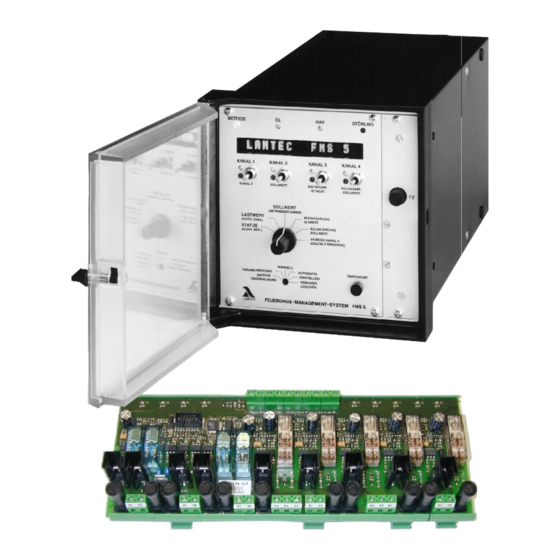
- Page 1 Quick Reference Combustion-Management-System FMS for Enduser TÜV-type approval CE 0085 AS 0254 Sensors and Systems for Combustion Engineering...
-
Page 3: Table Of Contents
Inhaltsverzeichnis Inhaltsverzeichnis GENERAL INFOMATION .........3 Validity of these instructions. -
Page 4: General Infomation
General Infomation General Infomation Validity of these instructions Standards The units conform to the following standards and regulations: FMS: EN 298 EN 230 EN 676 where applicable EN 267where applicable EN 12 953 - 7 u. 9 where applicable EMC-Directive, Low Voltage Directive, Gas Appliance Directive Integral leakage test: Test mark: EN 1643... -
Page 5: For Your Safety
The unit is approved for use only with an external automatic flame guard. The automatic flame guard type F 250 made by LAMTEC is used for testing purposes. The following flame monitoring systems / flame sensors are applicable for use (see the print no. - Page 6 LAMTEC GmbH & Co KG will not be liable for damage or injury arising out of a failure to ob- serve the instructions above. The warranty and liability provisions of the terms and conditions of sale and supply of LAMTEC GmbH &...
-
Page 7: Purpose
General Infomation Purpose Purpose FMS 4 / The FMS 4 / FMS 5 Combustion Management System is a control unit for FMS 4 / FMS 5 com- FMS 5 bustion systems. Brief description The FMS 4 adjusts up to four control elements as a function of a control variable (generally the burner load) according to freely programmable curves. - Page 8 General Infomation The FMS constantly monitors its own functions and these of the control elements connected. Each analogue input (control variable and feedback or correction) is freely configurable via plug-in cards. Alternatively: – potentiometer (1 - 5kΩ) – step input (DPS) –...
- Page 9 General Infomation Purpose internal This software option enables the calculating of the burner's required load setting continuously firing rate for a specified setpoint value (referred e.g. to temperature or pressure), through comparison controller with the actual value. This load setting can be notified internally to the electronic compound as the specified value.
- Page 10 TIP: You can download the up-to-date version of these instructions from http://www.lamtec.de as a PDF File You will find the version no. of this document at the backside of this document in the document number.
-
Page 11: Comissioning
Comissioning Comissioning O2-Regulation Resetting od: Manually Switch to "O regulation” mode. Press the Acceptance key and call up error text Push key 3 (2) upwards → error deleted. WARNING! If deleting an error, the error text must always first be called up by pressing the "Enter" key. Automatically: During each new burner start-up Calling up O2-... -
Page 12: System Operation
System Operation System Operation Mode Display Meaning of modes → "Switch-on sequence“ on the FMS → "Ready" ZÜ → "Ignition position" → "Setting/Ignition position" → "Base load" → "Setting/Base load" → "Post-ventilation" → "Off" → "Setting" → "Clear memory" → "Setting/Pre-ventilation"... - Page 13 System Operation indicates that although the mode selector switch is on "Setting” it is nev- ertheless performing the pre-ventilation routine. These is a signal on ter- minal 3. If the selector switch is on "Setting” and there is a "signal on terminal 3”, nevertheless the FMS maintains its control function.
-
Page 14: Curve Sets Fms (Option)
CRC 16 level 0: adjustable without password 1: adjustable by person commissioning 2: adjustable by the burner manufactorer or the boiler manufactorer 3: adjustable by LAMTEC only 4: adjustable by LAMTEC only oil safety time in seconds oil safety time in seconds... -
Page 15: Messages / Faults
System Operation Calling up running time meter Selector switch (1) to set-point Press "Enter" (3) and keep pressed – a moving text appears giving the following data: – total running hours – running hours on curve set 1 – starts on curve set 1 –... - Page 16 System Operation Alternative: FMS: Set signal on terminal 3 briefly (min. 2 seconds) via external switch. Fault is cleared! Calling up fault The FMS stores the last 10 faults with the associated running time meter. history Selector switch (1) to Status - current status appears on display Channel 1 switch (4) up - last fault code appears on display and the load values of the moment,...
- Page 17 System Operation O2- regulation perturbed In the event of perturbations, a warning message is displayed and the O regulator is deactivated. The specified base value "Without regulation” or the one for "Air shortage” is set. The display shows the running text "O regulation perturbed”.
- Page 18 System Operation The display of O history disappears automatically after 5 sec. O regulator faults lasting over 30 sec. are stored. They are only stored in the EEPROM, once the fault is cleared up or the FMS leaves the operating mode "Regula- tion"...
- Page 19 System Operation Fault Codes An "H" before the fault code indicates that the main processor has identified the cause of the defect. A preceding “Ü” indicates that the monitoring processor has triggered the fault. An * signifies that re-starting is permitted for this fault. A blinking Fault-LED means, that a autonomic restart will happen.
- Page 20 System Operation Aids FMS Aids ETA Potentiometer faulty, feedback changing too quickly: channel 1 Potentiometer faulty, feedback changing too quickly: channel 2 Potentiometer faulty, feedback changing too quickly: channel 3 Potentiometer faulty, feedback changing too quickly: channel 4 Potentiometer faulty, feedback changing too quickly: channel 5 151** Recirculation damper deactivated, out of time in reaching CLOSED position, channel: 1...
- Page 21 System Operation Aids FMS Aids ETA 201* 1st monitoring band under range too long: channel 1 B1,B3 202* 1st monitoring band under range too long: channel 2 B1,B3 203* 1st monitoring band under range too long: channel 3 B1,B3 204* 1st monitoring band under range too long: channel 4 B1,B3 205*...
- Page 22 System Operation Aids FMS Aids ETA Permissible O value was fallen below Internal communication between the processors faulty Output for internal load faulty Deviation between main processor and monitoring processor load values too great Deviation between main processor and monitoring processor too great: cor- A7,F6 rection channel 1 Deviation between main processor and monitoring processor too great: cor-...
- Page 23 System Operation Aids FMS Aids ETA Internal comparison: relay output terminal 36 not dropping out. A19,A7 Internal comparison: relay output terminal 41 not dropping out. A19,A7 Internal comparison: relay output terminal 76 not dropping out. A19,A7 Internal comparison: Output K203 not dropping out. Internal comparison: Output K201 entrapping out.
- Page 24 System Operation Aids FMS Aids ETA General safety chain missing Pre-ventilating signal present, without signal on terminal 2. G2,G5 Flame signal present, without signal on terminal 2. Flame signal appears during pre-ventilating. G2,G5 Flame signal goes out even though signal on terminal 2 is still present. Illegal operating mode change.
- Page 25 Error in reference element of main processor A7,A21 906* Error in reference element of monitoring processor A7,A21 Curve set adjustment via Lamtec System Bus, self-test recognizes fault 911* Error in reference, channel: 1 A7,A21 912* Error in reference, channel: 2...
- Page 26 System Operation Aids FMS Aids ETA Relay driver self-test: output terminal 41 faulty. A19,A7 Relay driver self-test: output terminal 76 faulty. A19,A7 Relay driver self-test: Output K203 defect. Relay driver self-test: Output K201 defect. Default language missing or LANGUAGE-FLASH defect Internal fault: main loop is too slow.
-
Page 27: Fms Fault Correction - Aids
System Operation FMS Fault Correction - Aids Display remains dark all LEDs are off Check whether there is a voltage present on the unit Check "F1" fuse (back of the unit , IEC power connector) Check connectors for correct seating Display remains dark or shows confused characters, Fault 111, 140 some or all LEDs light up,... - Page 28 The program EPROM may be defective. Fault 110 Request a new program EPROM from, LAMTEC, giving precise details of the order number and contract number at the time, the agent's order and all software checksum for the FMS. Please always return the defective EPROM (for address see back cover of this document).
- Page 29 The software version number displayed does not match the number on the configuration stick- The unit supplied possibly did not correspond to the order. Consult LAMTEC (for address see back cover of this document), since delivery the program EPROM has been changed and the new checksum is not noted.
- Page 30 System Operation Possible causes: – Relay module not connected or connected wrongly – Relay or relay module defective – External voltage is fed into the corresponding terminal – Terminal 9 and terminal 10 reversed – 24V fuse F2 (front panel) defective Check wiring Check relay –...
- Page 31 System Operation reference voltage External contact at connector loop possibly transposed, see D4 and E4 In the case of fault 904, 911, 915, in particular, check the corresponding reference. In the un- loaded condition (terminal open) it is 2.4 V. With potentiometer connected a little bit lower, de- pending on the resistance of the potentiometer.
- Page 32 System Operation At fuel oil flames: decrease flame scanner intensity (see Appendix) Motor does not move Check whether "OPEN" and "CLOSE" relays pull on when the switch (4) is operated. If not: Make sure that there is no fault (recognisable at the fault LED) Check F2 fuse (on power supply front panel) Check FMS relay-module connection If so:...
- Page 33 System Operation Control element does not react on changes to continuous output of the FMS. Measure continuous output in order to make sure, that the FMS is working correctly. Check output circuit to the control element. TIP: It is recommended that the FMS output signal is simulated with current transmitter. This makes it easy to locate the fault.
- Page 34 System Operation Load signal does not show the minimum value Cause: load transducer not on minimum Run transducer down manually Load signal cannot be changed Check whether fault present if so - Rest fault (selector switch on status switch up) if not Check load circuitIf only "000"...
- Page 35 System Operation Load rating does not attain the highest value indicated If the load transducer is in the maximum position but does not emit the highest possible value. Make sure that this position of the load transducer is the highest load rating position that oc- curs in operation.
- Page 36 System Operation A minimum value is not displayed in "Actual value” position and "AU” display On feedback via potentiometer: Cause: potentiometer connections transposed - Check terminals Cause: Potentiometer incorrectly fitted to the motor shaft - Turn potentiometer with the connected control element until the desired value is displayed. Cause: control element is not in "CLOSED”...
- Page 37 System Operation TIP: The feedback can be simulated by means of a current transmitter. This makes it easier to lo- cate the fault on the feedback circuit. Main and monitoring processor do not show the same feedback value, although the same sig- Fault 361 nal is fed to each of them Check limit switch position...
- Page 38 System Operation If the actual value is outside the 1 monitoring band, the compound is stopped. After the pa- rameterised time fault 231-235 occurs. The 2 monitoring band is standard 40 digit above the 1 monitoring band. If the actual value is outside the 2 monitoring band, there is an immediate shutdown (3 sec).
- Page 39 System Operation WARNING! If limit switches are adjusted after a curve has been programmed, the range limits must be re- entered. Only with the option "flying curve switching” Fault 161...165 With the option "flying curve switching" the 2 monitoring band is replaced by running direc- tion monitoring for up to 30 seconds after switching over.
- Page 40 System Operation The monitoring processor checks whether the present correction values lies within the range Fault 121...125 set. Check correction range Otherwise A7 Correction input is configured for 4 ... 20 mA, but the instantaneous value is < 4 mA. Fault 301, 302 Wire is possibly broken or connection poles are transposed.
- Page 41 System Operation Activate correction again – Selector switch 1 to "Status” – Channel 1 switch up – Check correction effect Selector switch (1) to "Load rating” Press "Enter” – instantaneous correction input is displayed If display >97%, check O regulator...
- Page 42 System Operation The curve set was changed during operation Fault 351, 760 Check wiring Especially the activation of terminal 75 TIP: Even if the software option "flying curve switching” is activated on the FMS, allowing the curve set to be changed during operation, it must be remembered that in "EI” mode (Setting) a flying change is not permitted.
- Page 43 System Operation The control unit has locked up Fault 600 - call-up running text and follow instructions there Check wiring and external signal transmitters e.g. - safety interlock chain boiler - safety interlock chain gas - air pressure monitor - safety interlock chain oil (special function) - fuel selection (special function) - external high firing rate acknowledgement - external ignition position acknowledgement...
- Page 44 System Operation Despite pre-ventilation, gas pressure is still/again present in the leakage test line. Fault 601 Main gas valve 1 (gas line side) leaking - Check valve Pressure switch in leakage test line defective or incorrectly set - Check pressure switch - Set pressure switch In the case of venting into the combustion chamber or over-roof: Main gas valve 2 (burner side) does not open...
-
Page 45: Servicing
System Operation Servicing 3.6.1 Changing EPROMs Changing a Pull out mains connector Data-EEPROM Release and remove front panel or a Pull out processor card (card fully to the left) and lay it down, remove any auxiliary card (on programming- processor card). EEPROM Carefully remove modules and replace with new ones. -
Page 46: Installing A New Software Version
FMS – main processor-EPROM on board down left handed Power ON – Display: LAMTEC FMS 4/5 – Self tests TIP: Please remember that the installation of modified software in a system that has already un- dergone acceptance will require a new acceptance or at least approval of the modification by the competent authorities. - Page 47 System Operation Replacing the The relais module for controlling the valves is subject to abrasion. This abrasion depends Relay module upon the load of the contacts and the numbers of the working cycle. 660 R 0016 WARNING! For safet reasons the relais module 660 R 0016 has to be replaced after 250 000 starts. The starts, the FMS has passed already, are shown under the function "Calling up running time meter"...
-
Page 48: Appendix
Appendix Appendix Process Sequence Charts 4.1.1 Gas Operation Gas operation with pilot burner, leakage test and ignition flame monitor... - Page 49 Appendix Gas operation without pilot burner, with leakage test...
- Page 50 Appendix Caption to the process sequence charts Any condition wait for SIC gas air pressure monitor min. scan time for pressure build-up in the gas test line (only 2 sec. available if leakage test is activated) running time servo drive 30-60 sec.
-
Page 51: Oil Operation
Appendix 4.1.2 Oil Operation Oil operation with pilot burner and flame monitor... - Page 52 Appendix Oil operation without pilot burner...
- Page 53 Appendix Caption to the process sequence charts any conditiong air pressure monitor min. scan time for pressure build-up in the gas test line (only 2 sec. available if leakage test is activated) running time servo drive delay re-circulation dumper 0 - t5 aeration time 30 - 999 sec.
-
Page 54: Connection Diagram Relay Modules
Appendix Connection Diagram Relay Modules 4.2.1 Connection Diagram Type 660 R 0016... -
Page 55: Block Diagram Type 660 R 0016
Appendix 4.2.2 Block Diagram Type 660 R 0016 *) At terminals 82 through 86 an alternating testing current must flow. Otherwise the relay mod- ule will switch off all outputs during the self-test which forces the FMS to do a fault-shutdown. At a mains voltage of 230V an impedance of Z<=100kW is required. -
Page 56: Wiring Of The Analogue Inputs
Appendix Wiring of the Analogue Inputs The following circuit diagrams are universal. They do not refer to the use of the respective channels. In addition all analog inputs (except correction) are drawn for potentiometer connec- tion. If current is used as input quantity on some channels, the respective inputs have to be wired as shown below. -
Page 57: Connecting Diagram Fms 4 / Fms 5
Appendix Connecting Diagram FMS 4 / FMS 5 FMS 4 Type 6 64 F 0010 with 4 three-point step control outputs FMS 5 Type 6 65 F 0010 with one continuous control and 4 three-point step control out- puts To be used only in a grounded power line network! - Page 58 Appendix FMS 4 Type 6 64 F 0020 with one continuous control and 3 three-point step control outputs FMS 5 Type 6 65 F 0020 with two continuous control and 3 three-point step control outputs To be used only in a grounded power line network!
- Page 59 Appendix FMS 4 Type 6 64 F 0030 with two continuous control and 2 three-point step control outputs FMS 5 Type 6 65 F 0030 with three continuous control and 2 three-point step control outputs To be used only in a grounded power line network!
- Page 60 Appendix FMS 4 Type 6 64 F 0040 with 3 continuous control and one three-point step control outputs FMS 5Type 6 65 F 0040 with 4 continuous control and one three-point step control outputs To be used only in a grounded power line network!!
- Page 61 Appendix FMS 4 Type 6 64 F 0050 with 4 continuous control outputs FMS 5 Type 6 65 F 0050 with 5 continuous control outputs To be used only in a grounded power line network!
- Page 62 Appendix FMS 4 / FMS 5 with burner firing rate controller To be used only in a grounded power line network!
-
Page 63: Technical Data
Appendix Technical Data Dimensions FMS 4 / FMS 5 Combustion Management System: 147 x 147 x 328 (L x W x D) in mm: Mounting depth Relay module 660 R 0011 77 x 112 x 70 Relay module 660 R 0013 77 x 70 x 60 Relay module 660 R 0131 77 x 70 x 80... - Page 64 Appendix Voltage supply 230 V + 10% - 15% 50/60 Hz To be used only in a grounded power line network! Power input approx. 34 VA Ambient temperature Operation: + 0° C…+ 60° C Transport and - 25° C…+ 60° C Storage Display Alphanumeric display, 16-digit switchable to set-point, load rating, status, actual value feed-...
- Page 65 Appendix Continuous control output Apparent 0 ...10 V > 5 kΩ ohmic resistance 0/4 ... 20 mA < 600Ω Signal outputs Monitor output 4 ... 20 mA signal, apparent ohmic resistance > 600 Ω Correction inputs: 2, adjustable to 0 ... 20 or 4 ... 20 mA channel and effect adjustable via parameters.
- Page 66 Appendix Fan (burner start) Contact for actuation of the fan motor and all other components that have to be activated at terminal 89 the start. max. 2 A, cos φ ≥ 0,8-1 (together with pre-ventilation signal) Gas operation signal Contact for signalling of the fuel selection. Not active in the off-state terminal 90 max.
- Page 67 Interface 2 serial interfaces on 25-pole Sub-D connector accessible only via adapter RS 232 (standard setting 19200 baud, parity none, 8 databits, 1 stopbit) LAMTEC-SYSTEM-BUS WARNING! Using the interface without adapter can damage the unit. Plug adapter in or remove only with the voltage off.
-
Page 68: Accessories And Spare Parts
Appendix Accessories and Spare Parts Accessories for FMS Combustion Novotechnik potentiometer 5 kΩ, Management System for VR, VMS / FMS TÜV-approved 6 60 P 7001 Contelec potentiometer 5 kΩ, for VR, VMS / FMS TÜV-approved 6 60 P 7003 Contelec potentiometer 5 kΩ, for VR, VMS / FMS TÜV-approved, short axis for conversion of L &... - Page 69 Appendix Spare parts for FMS Fuses 1A, T for VMS/FMS, 24V supply Combustion Management System (pack of 10) 6 60 R 0110 Fuses 3.15A, T for VMS/FMS, 230V (pack of 10) 6 60 R 0116 Fuses 3.15A, T for relay module 6 60 R 0011/R 0012 / R 0014 / R 0131 (pack of 10) 6 60 R 0115 Fuses 80 mA, T for relay module 6 60 R 0013...
- Page 70 Appendix Spare parts for FMS Combustion Management System Configuration module: 0 ... 20 mA / 5 kΩ 6 63 P 6000 PT 100 module 6 57 P 0990 Speed module 6 63 P 8001 Universal module for analogue inputs: Potentiometer 5kΩ 6 63 P 6000 0/4 ...
-
Page 71: Declaration Of Conformity
Appendix Declaration of Conformity Month / Year: :.........06.../...03....... Manufacturer: LAMTEC Meß- und Regeltechnik für Feuerungen GmbH & Co KG ................Address: Impexstraß5 5, 69160 Walldorf ................Product Designation: FMS 4 / FMS 5 Combustion Management System ................Type no.: CE 0085 AS 0254 ................ - Page 72 Appendix Appendix to the EC Declaration of Conformity or EC Manufacturer’s Declaration Month / Year: .........06.../...03....... Product Designation FMS 4 / FMS 5 Combustion Management System ............................................... The compliance of the designated product with the provisions of the above-mentioned Directives is verified by adherence to the following standards and regulations: Harmonised European Standards: Reference No...
- Page 74 LAMTEC Meß- und Regeltechnik LAMTEC Leipzig GmbH & Co KG Presented by: für Feuerungen GmbH & Co KG Wiesenstraße 6 Schlesierstraße 55 D-69190 Walldorf D-04299 Leipzig Telephone:(+49) 0 62 27 / 60 52-0 Telephone:(+49) 03 41 / 86 32 94 00...
Need help?
Do you have a question about the FMS Series and is the answer not in the manual?
Questions and answers