Sign In
Upload
Manuals
Brands
Lamtec Manuals
Controller
FMS 4
Lamtec FMS 4 Combustion Management System Manuals
Manuals and User Guides for Lamtec FMS 4 Combustion Management System. We have
3
Lamtec FMS 4 Combustion Management System manuals available for free PDF download: Manual, Quick Reference For End User, Quick Reference
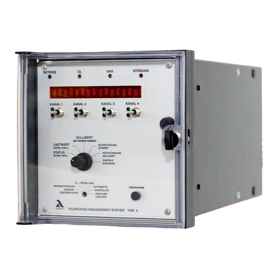
Lamtec FMS 4 Manual (162 pages)
Firing Management System
Brand:
Lamtec
| Category:
Controller
| Size: 4 MB
Table of Contents
Table of Contents
2
Adjusting the Integrated O Regulator (Optional)
2
Application-Internal O Regulator (Optional)
2
Connection to O Meter
2
Checking the O Influence
2
General Information
5
Validity of These Instructions
5
Intended Purpose of FMS 4 / FMS
5
Fms 4 / Fms
5
For Your Safety
6
Purpose
7
Application-Internal Output Regulator (Optional)
8
Using These Instructions
9
Purpose of These Instructions
9
Preliminary Clarification
9
Finding the Appropriate Section
9
Conventions
9
Fault Correction
10
FMS Operating Principle
11
FMS Digital Inputs
11
FMS Operating Sequence
11
Pre-Ventilation Suppression
11
Through an External Signal
12
Automatic Pre-Ventilation Suppression
12
Setting the Pilot Burner, Serving Mode
13
Program Monitoring Time
13
Restarting
13
Leakage Test (Option)
13
Curve Sets (Option)
13
Flying Curve Change (Option)
13
Automatic Fuel Change
13
Range Limits
13
Internal Load
14
Manual Operation
14
Parameterisation
14
Correction
14
Facility for Direct Connection
14
Of Namur Transmitter (Option)
14
Freedom from Error of Feedback Signals
14
Pre-Ventilation Limit
14
General Information
15
Energy-Saving Mode for Running Text Display
15
Separate Ignition Point
15
Integrated Power Control Unit (Option)
15
Integrated O Regulation
15
Settings
16
Inputs
16
Significance of ID Number
16
Configuration Sticker
16
Configuration Number
16
Condition on Delivery
17
Configuration Cards (Examples)
17
Processor Card
18
Power Supply Card
18
Parameters
19
Parameter Setting
19
Access Levels
19
Entering the Password
19
Changing Password
20
Changing Parameters
20
List of Parameters
21
List of Parameters (Level 0 and 1 Parameters Only)
22
List of Parameters
23
List of Parameters
24
List of Parameters
25
List of Parameters
26
List of Parameters
27
List of Parameters
28
List of Parameters
29
Leakage Test
30
Mode of Operation
30
Integrated Leakage Test (Option)
30
Leakage Test Flow Chart
30
Venting
31
Leakage Test Line Over-Roof
31
Calculation Formula
31
Suggested Circuit for Venting the Gas Line Over-Roof in Conjunction with the Combustion Management System
31
Output Regulator (Optional)
32
Output Regulator (Optional)
33
Output Regulator (Optional) Method of Operation
34
Thermostat and Control Region
34
Manual Control
34
Setting the Regulator
35
Control Region
35
Regulator Behaviour
36
Examples
38
Before Commissioning
39
Adjusting Motor Limit Switch
39
FMS Commissioning
40
Function Test
40
Significance of Fmsdigital Input Display
41
Setting Control Elements
42
Operation of Control Elements for Potentiometer
42
Programming Curves
43
Programming the Compound
43
Entirely New Curve, Clear Memory
43
Programming 1 Point
44
(Separate Ignition Point)
44
Programming with Burner Running
44
Programming with Burner Stationary
45
Nd Th
45
Programming 2 to 19 Point
45
Programming Last Top Point
46
Store Curve
46
Check Monitoring Values
46
Adding Points
47
Changing Curve Point
48
O Regulation
49
Automatic Functions Control During Operation
49
Checks During Burner Start-Up
49
O Monitoring Bands
49
O Boundary Curves
49
Dynamic Probe Test
50
Probe Blockage
50
Correction Output Monitoring
50
Regulation Strategy
51
With Pre-Setting for Load Changes
52
Extended Regulation Strategy (Air Shortage)
53
Via Analogue Interface
54
Operator Controls and Display
55
Mode Switching
55
Operator Controls and Display
56
Calling up O Regulation Text Messages
56
Commissioning
57
Setting the Correction Range
57
Calling up the Correction Range Set
59
Calculation and Setting of
59
Lag Time (Parameters 898/900)
60
P-Factor (Parameter 899)
60
Commissioning
61
Calling up the Base Value for O Regulation
61
Deactivated/Air Shortage
61
Automatic
61
Operation
62
The Meaning of the Additional Modes
62
Calling up O Regulation Text Messages
62
Correction
63
Set Correction Input
63
Setting the Correction Range
65
Recall Set Correction Range
65
Altering the Correction Range
66
Correction Modes
66
Run to Shut-Off Limits
67
Checking the Shut-Off Limits at the
68
Tolerance Limits Direction Air Deficiency
69
Indication for an Example Protocol
69
Example Protocol
70
Tips & Tricks
71
Programming 1St Point
71
(Ignition Load Point)
71
Programming with Burner Running
71
Programming with Burner Stationary
72
Reversing the Programming
72
Instrumentation for Commissioning
72
Adjusting Load Ratings Individually
73
Entering an Initial Curve
73
Approaching Control Elements from One Side
74
Entering Settings
74
Entering Top Setting
74
Ignition Delay When Setting
74
Pre-Setting Load Automatically
74
Tips & Tricks
75
Entering the Compound Curves with the Burner Stationary
75
Keeping the Re-Circulation Damper Closed in Pre-Ventilation
75
Setting the Pilot Burner (Servicing Mode)
75
Switching the Burner on Again Via the Target Value
75
System Operation
76
Mode Display
76
Significance of Modes on the FMS
76
O Regulator Modes
77
ES" Mode Progress (Set-Control)
78
Continue Programming
78
Curve Sets FMS (Option)
79
Interconnection with 4 Curve Sets Option
79
Checksums Running Time Meter
80
Recalling the Checksums and the Safety Times
80
Calling up Running Time Meter
80
Messages / Faults
81
What Happens in the Event of FMS Fault
81
Reading off a Fault
81
Resetting a Fault
81
Calling up Fault History
81
O Regulation Perturbed
82
Air Shortage Perturbation
82
Resetting O Errors
82
Calling up O Regulation Error History
82
Fault Codes
83
FMS Fault Correction Aids
90
General Faults (A)
90
Three-Point Step Control Output (B)
95
Continuous Output (C)
97
Load Signal (D)
98
Feedback (E)
100
Feedback (E)
103
Correction Input (F)
104
Correction Input (F)
105
Digital Inputs (G)
106
Control Unit Faults (H)
107
Leakage Test
108
FMS Fault Correction
109
Parameters (P)
109
Parameter (P)
112
Aids
115
Parameters (P)
118
Servicing
119
Changing Eproms
119
Changing a Data EPROM
119
Or a Program EPROM
119
Re-Entering Range Limits
119
Servicing
120
Installing New Software Version
120
Procedure for Installation of
120
New Software in the FMS
120
Appendix
121
EMC of Wiring
121
Connection of Screening
121
PE Bus Bar
121
Switch Cabinet Wiring
121
Screening of Leads from the Field
121
Feedback on TPS Channels
122
Positive Connection
122
Example of Positive
122
Potentiometer Connection
122
Error-Proof Feedback
122
Examples of Potentiometers
122
Examples of Servomotors
122
External Switching of the Fuel Control Element
123
Replacing a Servomotor Replacing a Potentiometer
124
Replacing a Complete Servomotor
124
Replacing the Potentiometer in a Servomotor
125
Switch and Key Combinations on the VMS / FMS Front Panel
126
Switch and Key Combinations
126
O Regulation
127
Notes on Air Pressure Monitor
128
Interconnection of the Air Pressure Monitor
128
Re-Circulation Pre-Ventilation Time
128
Interconnection of Monitors
128
Notes on Start Without Pre/Ventilation
129
Process Sequence Charts
130
Gas Operation with Pilot Burner
130
Gas Operation Without Pilot Burner
131
Oil Operation with Pilot Burner
132
Process Sequence Charts
133
Relay Module R16
134
R Elay Module R16
137
Safety Interlock Chain
138
Wiring of the Analogue Inputs
139
Connection Diagram
140
Connection Diagram
142
With Output Regulator
145
Direct Connection of 122 Namur Transmitter (Option)
146
Technical Data
146
Selecting a Suitable Sensor
147
Relay Module Connection Diagram
148
Connection Diagram Modem for Remote Control
149
General Notes
150
Technical Data
151
Technical Data
152
Accessories and Spare Parts
156
Accessories and Spare Parts for
157
FMS Combustion Management System
158
Declaration of Conformity
158
EC Declaration of Conformity
158
Appendix To the EC Declaration of Conformity or EC Manufacturer's Declaration
159
Protocol Example
160
Target Value Curves
161
Advertisement
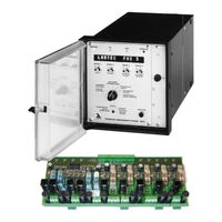
Lamtec FMS 4 Quick Reference For End User (74 pages)
Combustion-Management-System
Brand:
Lamtec
| Category:
Control Systems
| Size: 8 MB
Table of Contents
Table of Contents
3
1 General Infomation
4
Validity of These Instructions
4
For Your Safety
5
Purpose
7
2 Comissioning
11
O2-Regulation
11
3 System Operation
12
Mode Display
12
Curve Sets FMS (Option)
14
Check Sums - Running Time Meter
14
Messages / Faults
15
FMS Fault Correction - Aids
27
Servicing
45
Changing Eproms
45
Installing a New Software Version
46
4 Appendix
48
Process Sequence Charts
48
Gas Operation
48
Oil Operation
51
Connection Diagram Relay Modules
54
Connection Diagram Type 660 R 0016
54
Block Diagram Type 660 R 0016
55
Wiring of the Analogue Inputs
56
Connecting Diagram FMS 4 / FMS 5
57
Technical Data
63
Accessories and Spare Parts
68
Declaration of Conformity
71
Lamtec FMS 4 Quick Reference (18 pages)
Combustion Management System
Brand:
Lamtec
| Category:
Industrial Equipment
| Size: 0 MB
Table of Contents
Table of Contents
3
1 General Information
4
Validity of These Instructions
4
2 Safety
5
Explanation of the Symbols in the Safety Notes
5
3 Commissioning
6
Trim
6
Resetting Faults
6
Calling up O 2 Trim Text Messages
6
4 System Operation
7
Mode Display
7
Mode Abbreviations Used
7
O 2 Trim Modes
8
Check Sums - Hours of Operation
9
Calling the Checksums
9
Displaying the Running Time Meter
10
Messages / Faults
10
What Happens if There Is a Fault
10
Reading Faults
11
Resetting Faults
11
Recalling Fault History
12
What Happens if a Fault Occurs in the O 2 Trim
12
Air Deficiency Failure
13
Resetting O 2 Errors
13
Calling Fault History O Trim
13
Maintenance
14
Replacing Relay Module R16
14
5 Appendix
15
EU Declaration of Conformity
15
Advertisement
Advertisement
Related Products
Lamtec FMS Series
Lamtec FMS 5
Lamtec FA1
Lamtec F200K2 IR-1
Lamtec F200K1 IR-2
Lamtec F200K1 IR-1
Lamtec F300K Series
Lamtec F300K UV-4.6
Lamtec F300K IR-2
Lamtec F300K IR-3
Lamtec Categories
Control Unit
Controller
Industrial Equipment
Transmitter
Control Systems
More Lamtec Manuals
Login
Sign In
OR
Sign in with Facebook
Sign in with Google
Upload manual
Upload from disk
Upload from URL