Table of Contents
Advertisement
Table of Content
��
Getting Started ................................................................................................................................
One-Stop-Shop - The Model Railway Center of the Future .................................................................
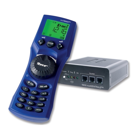
multiMAUS
Part 1 • Basics - Become Familiar with the multiMAUS
1.4 multiMAUS
PRO
2.1.1 First-Time Use .................................................................................................................
2.2.1 Library Mode ...................................................................................................................
2.2.2 Entering a New Locomotive ..............................................................................................
2.2.3 Locomotive Address Mode ...............................................................................................
2.3 Driving and Functions ..................................................................................................................
2.4.1 Emergency Stop ..............................................................................................................
2.4.2 Selective Locomotive Stop ...............................................................................................
2.5.1 Setting up Double Heading ..............................................................................................
2.5.2 Double Heading Tips ........................................................................................................
2.5.3 Deleting Double Heading .................................................................................................
2.6 Turnout control ...........................................................................................................................
2.7.1 Creating a New Route ......................................................................................................
2.7.2 Activating and Deactivating Routes ..................................................................................
2.8 Quick Programming of Locomotives and Decoders .......................................................................
2.9 Short Circuit and Overload ..........................................................................................................
Part 3 • Menus - Programming for advanced users
Overview of the Menu Structure ..........................................................................................................
3.1 The "LOCO" Menu .......................................................................................................................
46
Overview ..................................................................................
PRO
and multiZENTRALE
PRO
: The Keys ..............................................................................................................
.............................................................................................
.............................................................................................
.................................................................
PRO
2
48
48
49
50
50
51
53
53
53
54
56
56
57
58
58
59
59
60
62
63
64
65
66
68
70
Advertisement
Table of Contents

Subscribe to Our Youtube Channel
Related Manuals for roco multiMAUSPRO


Summary of Contents for roco multiMAUSPRO
-
Page 1: Table Of Contents
Table of Content �� Getting Started ..........................One–Stop–Shop – The Model Railway Center of the Future ..............multiMAUS and multiZENTRALE Overview .................. Part 1 • Basics – Become Familiar with the multiMAUS and multiZENTRALE 1.1 Connecting the multiMAUS and multiZENTRALE .............. - Page 2 Table of Content �� 3.2 The “PROGRAMMING” Menu ....................... 3.3 The “SETTINGS” Menu ........................ 3.4 “ROUTES” Menu ......................... Part 4 • multiZENTRALE 4.1 Power Supply ..........................4.2 Connections ..........................4.3 Main and Programming Track ..................... 4.4 Resetting the multiZENTRALE ....................4.5 Updating the multiZENTRALE and multiMAUS ..............
-
Page 3: One-Stop-Shop - The Model Railway Center Of The Future
• Rotary knob with zero locking position • Compatibility with other DCC / NMRA-compatible controllers • The ROCO digital system is expandable to include up to 31 input devices such as extra Lokmaus/multiMAUS units or multiMAUS , route controller units, etc. -
Page 4: Pro Pro
– A transformer or switching power supply unit (e.g. ROCO 10850, Fleischmann 681301, see also page 80), – A feeder track without capacitor (e.g. geoLINE 61190, ROCO LINE 42517, Fleischmann 9400, 22217 (N), 6430 H0). -
Page 5: Multizentrale
Your new multiZENTRALE is equipped with LED indicator lights that provide a quick overview over the most important functions of your ROCO digital system. You should place the control center where you can easily see �� the LEDs. Green: If the green LED (all the way to the left) lights up, a wireless con-... - Page 6 A completely depicted wireless symbol in the display indicates an optimal connection. The better the connection, the more bars are displayed. If the wireless connection is very bad, only the antenna symbol is depicted. If this is the case, it is pos- ��...
- Page 7 Keys Function In drive mode: – Emergency stop on entire system Stop key �� In menu mode: – Return from the respective menu level —— in combination with —— In drive mode: – Selective emergency stop for the locomotive selected and displayed Shift key In the „ROUTE“...
-
Page 8: Part 2 • Operation - Driving And Switching
Part 2 • Operation – Driving and Switching �� Despite its numerous options, operation of the multiMAUS is simple and intuitive. A concept which had already been successfully introduced for the Lokmaus models of the first and second generation. The following shows you how to operate the multiMAUS based on practical examples. -
Page 9: Entering A New Locomotive
• Calling up other locomotives already entered in the library (“scrolling”) �� Locomotives in the library are sorted in the order in which they were entered. You can of course change this order: Select locomotive These key combinations (press keys together) move the locomotive up or down in the library. You can check the new order for the library with the arrow keys. - Page 10 Display message Input Comment Confirm by pressing “OK.” �� The multiMAUS then switches to the locomotive address. The “suggested value” is displayed, in this case “3.” Change the suggested value by either using the “shift” key and one of the “arrow …...
-
Page 11: Locomotive Address Mode
2.2.3 Locomotive Address Mode The multiMAUS also gives you the option of controlling your locomotives us- ing the decoder address only. The display screen shows the locomotive address with the letter “L” before it (in this case, locomotive address 36), the locomotive ��... -
Page 12: The Emergency Stop Functions
�� See the operating manual for the functions which are available for your locomotive. • You switch the locomotive light on or off using the “Light /OK” key. The star “ ” at the bottom right of the display lights up to confirm that the locomotive lighting is switched on. Off... -
Page 13: Selective Locomotive Stop
The locomotive stop is released by turning the controller, the locomotive starts to move again. Double Heading The new ROCO digital system also allows for double heading, which means controlling two locomotives in front of a train. Two locomotives are coupled and can be controlled centrally at once from one of the two locomotive addresses. -
Page 14: Double Heading Tips
Input Display message Comment The display depicts “EQUAL DIRECTION”. You now set up the direction of travel of the second loco- �� motive in reference to the first locomotive. The last selected direction of travel of the locomotives is not the decisive factor here but the position of the driver cabs. -
Page 15: Turnout Control
Turnout control You can use the multiMAUS to control up to 2,048 digital turnout drives with genuine turnout addresses without having to use up a locomotive address (as is the case with the Lokmaus 2 /R3). To do so, you can ��... - Page 16 Input Display message Comment After the “Locomotive /turnout” key has been pressed, the multiMAUS switches from drive �� mode (library or locomotive address mode) to turnout mode. The turnout last called up always appear. In this case, turnout “6”, position “straight-on.” The flashing cursor indicates that the turnout address can be entered.
-
Page 17: Routes
Routes The multiMAUS does not only offer the possibility to switch individual turnouts but can also combine several turnouts into one route and switch together by pressing only one key. A route is a distance covered �� by a train crossing several turnouts. For example, this can be used to move a freight train from a feeder track across sever turnouts switched with a single command and onto the main track without interruption. -
Page 18: Activating And Deactivating Routes
Input Display message Comment Enter the number of the first turnout of the … route, in this case turnout number 5 set to �� a branch line. After entering the number “5”, the number flashes until the next step of the route has been configured. -
Page 19: Quick Programming Of Locomotives And Decoders
If programming is carried out on the regular track and if more than one digital locomotive is located on that track (or turnout decoders other than the ROCO articles 42624 and 10775), the settings of all decoders in the system are changed with one programming command. This means it is possible to accidentally change all decoders to the same locomotive address, for example. -
Page 20: Short Circuit And Overload
Shortcuts” in Part 5 for additional help. Short Circuit and Overload If a system short circuit or overload occurs, the ROCO digital system in- dicates this in two different ways. Two symbols flash in the display of the multiMAUS , namely a lightning or thunderbolt symbol and the STOP sign. -
Page 21: The Menu Functions Of The Multimaus
Part 3 • Menus The Menu Functions of the multiMAUS �� The multiMAUS has four main menus with which you can both perform comprehensive programming and change the basic settings of the multiMAUS . This menu level can be accessed using two simple key combina- tions: –... - Page 22 There are two ways to exit the menu level: • Press the “STOP” key. You may need to do this several times depending on the submenu which you are cur- rently in. Each time you press “STOP” you go back one level. •...
-
Page 23: Overview Of The Menu Structure
�� Menu 1: Menu 2: CV MODIFICATION LOCO PROGRAM LONG ADDRESS REVERSE DIRECTION 28 SPEED STEPS DELETE ANALOG DRIVING NMRA-BIDI SPEED TABLE LONG ADDRESS SEARCH SEND PROG-MODE NO READING BIT ONLY RECEIVE READ-MODE BYTE ONLY BIT AND BYTE ADDRESS LIBRARY... - Page 24 BACKLIGHT CONTRAST �� Menu 3: Menu 4: DISPLAY TIME SETTINGS ROUTES LANGUAGE MENU-KEY-TIME USERINTERFACE EDIT FUNCTION KEYS CHILD LOCK CANCEL SETTINGS RESET DELETE LOCO-LIBRARY ROUTES DOUBLE HEADING STOPKEY REVERSE DIRECTION SPEED TABLE TURNOUT FACTORY RESET RADIO INTERRUPTION ROUTES STOPMODE MODE CALIBRATION DELAY SOFTWARE...
-
Page 25: The "Loco" Menu
The “LOCO” Menu �� The multiMAUS uses the “LOCO” menu to manage all data which is required for the locomotive library and for identification of a locomotive. You can also use this menu to set the multiMAUS to library or address mode. “NEW”... - Page 26 “SEARCH” This could be one of the most important functions of your multiMAUS . You can use this menu item to as- �� sign a locomotive address to the corresponding locomotive in the library. Simply enter a locomotive address using the “function keys” and the multiMAUS will find the correspond- ing locomotive in the library.
-
Page 27: The "Programming" Menu
�“bits and bytes” listed in the glossary in Part 5 of the menu. ROCO decoders already installed in locomotives are usually delivered with suitable settings. Check before performing programming whether it is really necessary. See the instruction manual for your decoder or lo- comotive. - Page 28 Please consult the decoder manual for details about the function and configuration options of the CV 29. To simplify programming, ROCO has labeled the individual configuration options. – The first image of the display depicts “C 29” and then immediately switches to the first configuration op- tion “REVERSE DIRECTION”...
- Page 29 “READ MODE“ Use this menu to configure the readout options of the multiMAUS . Data are then read out with “CV MODI- �� FICATION,” “CV29,” and “CVBIT.” Select the respective subitem with the arrow keys and confirm with the “Light /OK” key. Factory setting: “BIT AND BYTE”...
-
Page 30: The "Settings" Menu
3.2.1 Another language for the menu navigation is selected using the “LANGUAGE” submenu. Select your language using the “arrow keys”. If your national language is not included, visit the ROCO website “www.roco.cc” for an update. – To confirm, press the “Light /OK” key. You return to the start level “LANGUAGE.”... - Page 31 3.2.4 The multiMAUS has “CHILD LOCK” which can be set tomultiple levels and can be activated after calling up the menu item using the “arrow keys.” To block an area, you will need to enter a code which is comprised of 4 numbers (no letters!). The pass- word is then always requested when you wish to call up a protected area of the multiMAUS ��...
- Page 32 system from the mains power supply (“DISABLE VOLTAGE”) or whether this only stops the locomotives (“EMERGENCY STOP”). Use the arrow keys to make a selection and confirm with “Light /OK.” Factory setting: DISABLE VOLTAGE You can still trigger a “selective emergency stop” that only affects the selected locomotive in spite of this ��...
- Page 33 stays lit, the wireless symbol appears in the display of the handheld unit. 3.6.2 “PANID” is information only for service technicians. 3.6.3 “NUMBER OF CHANNELS” �� The wireless connection between the multiMAUS and the multiZENTRALE uses technology that protects the system from interference from other wireless networks such as a WLAN. The devices search automatically for the best wireless channel for optimal wireless transmissions when being paired.
-
Page 34: Routes" Menu
“ROUTES” Menu �� The multiMAUS uses the “ROUTES” menu to manage all data, which is required for the locomotive library and for switching the corresponding turnouts. “NEW” Use this menu item to add a new route to the library. The sequence of steps is described and depicted in detail starting on page 62 (Part 2, Chapter 2.7). -
Page 35: Part 4 • Multizentrale
If these three connections are not enough, use the data bus distributor 10758 to connect additional de- vices. • The “feedback BUS” socket is intended for feedback modules such as the ROCO Art. No. 10787. Up to 20 feedback modules can be connected to the BUS line originating from this module. The feedback modules... -
Page 36: Resetting The Multizentrale
Simply connect the multiZENTRALE to the USB port (USB 1.1) of a PC (Windows 98 SP 2 or higher). Download and start the update program available from the ROCO Internet site. Follow the instructions of the user menu. Note: • During the update process of the multiZENTRALE... -
Page 37: Pro Pro
Even locomotives made by other manufacturers can be equipped with ROCO decoders if the necessary room for installation is available. If they are equipped with a digital interface the conversion is just as easy as with a ROCO locomotive. If you wish to install the 10745 load-controlled locomotive decoder, the locomotive will require a direct... -
Page 38: Connecting Several Controllers
Combination of Digital and non-Digital System Parts All ROCO digital locomotives can be driven on both digital and “normal” direct current systems without any complications. The locomotive decoder automatically detects the type of system it is on. It is therefore simple to use both types of systems together so that you can still use non-digital locomotives on the direct current section of the system. -
Page 39: The Booster 10765
Switch off the system before installing a booster. Divide the system into supply sections. Disconnect the tracks electrically from each other in the respective places (on both sides!) wether using ROCO insulating rail connectors 42611 or 61192, insulated track or by sawing the rail profiles. Install a section of power track (e.g. 61190) in the new supply section and connect it to the “Track Out”... -
Page 40: Glossary
The ROCO 10769 terminal loop module solves the problems of a terminal loop in digital operation. Isolate the terminal loop with both poles on both sides by disconnecting the terminal loop completely from the rest of the system, using either insulated connectors or by sawing the rail profiles (see fig. 6 on page 93). It is imperative that the isolated section of track within the terminal loop is longer than the longest train which is going to travel ��... -
Page 41: Tips, Information, And Shortcuts
analogue direct current locomotive but is a necessary addition and must also be given a place in the locomotive housing. For alternating current locomotives on the other hand, the change-over module or relay is replaced by the decoder, not in DCC format but of course Motorola format. ��... -
Page 42: Programming Help For Lokmaus 2 /R3 - Multimaus
MAUS multi Previous operating manuals for digital ROCO articles (e.g. 42624 turnout drive) only describe the standard pro- gramming mode for Lokmaus 2 /R3. The following includes a table which compares the programming procedure for the Lokmaus 2 /R3 and quick programming (see chapter 2.8 on page 64) on the multiMAUS For more information see the operating manual for the Lokmaus 2 /R3. - Page 43 Fig. 1 � �� LC-Display Stop-Taste LC display Stop Key � Écran touche »Stop« LC display Tasto di arresto � Pfeiltaste Pfeiltaste (links) (rechts) Arrow Key Arrow Key (left) (right) touche »flèche« touche »flèche« (à gauche) (à droite) Tasto freccia Tasto freccia (sinistra) (destra)
- Page 44 � Aufbau des ROCO Digital-Systems (Europa-Version mit 230 V). Setting up the ROCO digital system (Europe version with 230 V). Structure de la commande numérique ROCO (version européene à 230 V). Struttura del sistema digitale ROCO (versione europea a 230 V).
- Page 45 Fig. 3 � multiZENTRALE �� � � Anschluss Hauptgleis Programmiergleis Main track connection Programming track Câblage de la voie principale Voie de programmation Binario principale di collegamento Binario di programmazione Anschluss von Haupt- und Programmiergleis an die multiZENTRALE Connection of main and programming track to the multiZENTRALE Comment câbler la voie principale et de programmation avec multiZENTRALE Collegamento del binario principale e di programmazione alla multiZENTRALE...
- Page 46 Fig. 4 � �� � � Anschluss eines Boosters 10765 an die multiZENTRALE und die Gleisanlage. Wiring diagram of the multiZENTRALE , the booster 10765 and the tracks. Comment câbler l‘amplificateur complémentaire réf. 10765 avec multiZENTRALE et la voie. Come collegare multiZENTRALE , il booster 10765 e i binari.
- Page 47 Fig. 5 � �� � � Übergangsstrecke Digital — Gleichstrom mit dem Trennmodul 10768 (werkseitig ausverkauft). Pass-over section with additional tracks from digital to DC-layout controlled by the Separator module 10768 (Sold out by the factory). Canton de transition de la section en commande numérique à celle en commande analogique avec le module 10768 (vendu en usine).
- Page 48 Fig. 6 � �� � � ����� ����� Symbolische Darstellung Symbolic Illustration Illustration figurative rappresentazione simbolica Eine digitale Kehrschleife mit den Kehrschleifenmodulen 10769 (werkseitig ausverkauft) oder 10767. A digital turning loop with the turning loop control module 10769 (sold out by the factory) or 10767. Branchement d‘une boucle de retournement en commande numérique contrôlée par les modules 10769 (vendu en usine) ou 10767.
- Page 49 Plainbachstraße 4 | Postfach 96 reference! • Pière d‘bien vouloir conserver ce mode d’emploi en vue d’une future utilisation! • Conservate 5101 Bergheim | Österreich queste istruzioni per un futuro utilizzo! • Deze handle- www.roco.cc ding altijd bewaren. �������������������� ���������������������������� 8010832920 XI /2009 ��������������������...
Need help?
Do you have a question about the multiMAUSPRO and is the answer not in the manual?
Questions and answers