Table of Contents
Advertisement
Quick Links
Keysight Wireless
Connectivity Test Set
This help file provides documentation for the
following products:
E6650A EXF Wireless Test Set for Femtocell
Notice: This document contains references to Agilent.
Please note that Agilent's Test and Measurement
business has become Keysight Technologies. For more
information, go to www.keysight.com.
V9065B Sequence
Analyzer User's &
Programmer's
Reference
Advertisement
Table of Contents

Related Manuals for Keysight E6650A EXF


Summary of Contents for Keysight E6650A EXF
- Page 1 Connectivity Test Set This help file provides documentation for the following products: E6650A EXF Wireless Test Set for Femtocell Notice: This document contains references to Agilent. Please note that Agilent’s Test and Measurement business has become Keysight Technologies. For more information, go to www.keysight.com.
-
Page 2: Source Marker
No additional INFORMATION CONTAINED HEREIN. Edition: 1, July 2015 government requirements beyond SHOULD KEYSIGHT AND THE USER HAVE A those set forth in the EULA shall apply, Published by: SEPARATE WRITTEN AGREEMENT WITH except to the extent that those terms, WARRANTY TERMS COVERING THE Keysight Technologies, Inc. -
Page 3: Table Of Contents
Table of Contents Table of Contents V9065B Sequence Analyzer User's & Programmer's Reference Table of Contents 1 About the Test Set Installing Application Software Viewing a License Key Obtaining and Installing a License Key Updating Measurement Application Software EXF Options and Accessories Front-Panel Features Display Annotations Rear-Panel Features... -
Page 4: Table Of Contents
Table of Contents Operation Condition Query Operation Enable Operation Event Query Operation Negative Transition Operation Positive Transition Preset the Status Byte Questionable Register Questionable Condition Questionable Enable Questionable Event Query Questionable Negative Transition Questionable Positive Transition Questionable Calibration Register Questionable Calibration Condition Questionable Calibration Enable Questionable Calibration Event Query Questionable Calibration Negative Transition... - Page 5 Table of Contents Questionable Temperature Event Query Questionable Temperature Negative Transition Questionable Temperature Positive Transition Common Commands All (Daily use) Clear Status Standard Event Status Enable Standard Event Status Register Query Identification Query Operation Complete Query Instrument Options Recall Instrument State *RST (Remote Command Only) Save Instrument State Service Request Enable...
- Page 6 Table of Contents Delete Point Delete Correction Apply Corrections Delete All Corrections Remote Correction Data Set Commands Set (Replace) Data (Remote Command Only) Merge Correction Data (Remote Command Only) Freq Ref In Sense Internal External Ext Ref Freq RF Output & Test Set Config RF Output RF Output RFIO1...
- Page 7 Table of Contents 150 kHz Highpass (Remote Command Only) Protective Earth (Remote Command Only) 4 Mode Functions Mode More Information Sequence Analyzer W-CDMA with HSPA+ GSM/EDGE/EDGE Evo Analog Demod TD-SCDMA with HSPA/8PSK WLAN LTE-Advanced FDD LTE-Advanced TDD Application Mode Number Selection (Remote Command Only) Application Mode Catalog Query (Remote Command Only) Application Identification (Remote Commands Only) Current Application Model...
- Page 8 Table of Contents Print Maximize/Restore Down Maximize Restore Down Page Setup Print Restore Down Minimize Exit Print System Show Errors Previous Page Next Page History Verbose SCPI On/Off Refresh Clear Error Queue Status Input Overload Enable (Remote Command Only) Power Up (Remote Command Only) System Show System contents (Remote Command Only) Computer System description (Remote Command Only)
- Page 9 Table of Contents Mode and Input/Output Defaults User Preset Last State Power On Application Configure Applications Preloading Applications Access to Configure Applications utility Virtual memory usage Select All Deselect All Move Up Move Down Select/Deselect Save Changes and Exit Exit Without Saving Restore Power On Defaults Configure Applications - Instrument boot-up Configure Applications - Windows desktop...
- Page 10 Table of Contents User Agilent Restore Defaults Restore Input/Output Defaults Restore Power On Defaults Restore Align Defaults Restore Misc Defaults Restore Mode Defaults (All Modes) Control Panel… Licensing… Security Read-Write Read only Diagnostics Show Hardware Statistics SCPI for Show Hardware Statistics ( Remote Commands Only) Advanced Key Recorder Self test...
- Page 11 Table of Contents Select Marker Couple Markers All Markers Off Peak Search List Sequence Measurements Measurement Commands for List Sequencer Remote Command Results for List Sequencer Measurement non_parameter_table_9.485293 10.48203 58.26797 Condition Results Returned Mode = Sequence Analyzer Not specifiedor n=1 If the Sequence is aborted due to “Abort on Error”, then results return NANs from point of failure and valid results prior to that.
- Page 12 Table of Contents Modulation Accuracy Results WCDMA Modulation Accuracy (Rho) Results LTE FDD Modulation Accuracy Results TD-SCDMA Modulation Accuracy (Rho) Results WLAN Modulation Accuracy Results WLAN MIMO Modulation Accuracy Results QPSK EVM Results Code Domain Power Results WCDMA Code Domain Power Results TD-SCDMA Code Domain Power Results Integrity Indicator Remote Measurement Functions...
- Page 13 Table of Contents Command to set up analyzer sequence for ILPC measurement Command to query the sequence version for sequence studio Command to setup multiple analysis steps Cooperation Parameter Enable WLAN Multi Radio Standard in Sequence analyzer Measurement Parameter Setup (for measurements from other modes) PVT Meas Setup GSM/EDGE PVT Meas Setup LTE-TDD PVT Meas Setup...
- Page 14 Table of Contents 1xEV-DO Pre-defined Offset/Interval TDSCDMA Analysis Timeslot TDSCDMA HSPA/8PSK Enable TDSCDMA Demod – Scramble Code TDSCDMA Demod – Uplink Pilot TDSCDMA Demod – Sync Type TDSCDMA Demod – Switching Point TDSCDMA Demod – Max Users for Traffic TS0 TDSCDMA Demod –...
- Page 15 Table of Contents Analyzer Table Source Table Excel Spreadsheet Programming Acquisitions Via SCPI Acquisition Setup using SCPI Analysis Step Setup Validation and Setup dependencies Meas Setup Result Type Measurement Metrics Display Results ON/OFF Display Results ON/OFF Acquisition Setup using SCPI Number of Acquisitions Current Acquisition Insert Before Acquisition...
-
Page 16: Register 1 Thru Register
Table of Contents NONE Internal Integration Type Normal Primary Lower Upper Range Ext Switch MIMO Acquisition RF Input Port RFIO1 RFIO2 RF Input Analysis Step Setup Number of Analysis Steps Current Analysis Step Insert Before Analysis Step Delete Analysis Step Analysis Offset Analysis Interval Measurement Bitmap... - Page 17 Table of Contents Trigger Holdoff Trig Holdoff Holdoff Type Video Trig Slope External 1 Trigger Level Trig Slope External 2 Trigger Level Trig Slope IF Gain Low Gain High Gain Meas Preset RF Input Port Mode Mode Mode Preset How-To Preset Print Quick Save Recall...
- Page 18 Table of Contents More Information Register 1 thru Register 16 Register 1 thru Register 16 Mass Storage Catalog (Remote Command Only) Mass Storage Change Directory (Remote Command Only) Mass Storage Copy (Remote Command Only) Mass Storage Device Copy (Remote Command Only) Mass Storage Delete ...
- Page 19 Table of Contents GSM/EDGE Channel Number Ranges W-CDMA Channel Number Ranges CDMA 2000 / 1xEVDO Channel Number Ranges LTE FDD Channel Number Ranges LTE TDD Channel Number Ranges TDSCDMA Channel Number Ranges Radio Setup Radio Standard Radio Band Link Set Reference Frequency Freq Reference Freq Offset Modulation Setup...
- Page 20 Table of Contents Insert Step Before Delete Step Clear List Step Trigger Transition Time Radio Setup Channel Frequency Power Waveform Step Duration Output Trigger Step Configuration (Remote Command Only) Clear List (Remote Command Only) Trigger Type BeginningOfStep DataMarker Manual Trigger Now Remote Software Trigger (Remote command Only) Query List Sequence Initiation Armed Status (Remote Command Only) Source Preset...
-
Page 21: About The Test Set
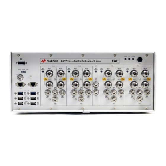
Sequence Analyzer User's & Programmer's Reference 1 About the Test Set The X-Series E6650A EXF Wireless Test Set for Femtocell is a one- box tester consisting of instruments loaded into a M9018A PXI mainframe with a front impact cover. The mainframe has a common PC controller (located on the far left) and M9300A PXI Frequency Reference (located in the center of the rack). -
Page 22: Installing Application Software
You may want to keep a copy of your license key in a secure location. To do this, you can print out a copy of the display showing the license numbers. If you should lose your license key, call your nearest Keysight Technologies service or sales office for assistance. - Page 23 If the application you are interested in licensing is not available, you will need to do a software update. (To display a list of installed applications, press System, Show, System.) Check the appropriate page of the Keysight web site for the latest available software versions, according to the name of your instrument, as follows: http://www.keysight.com/find/E6650A_software...
-
Page 24: Exf Options And Accessories
You can view an online list of available Options and Accessories for your instrument as follows: 1. Browse to one of the following URLs, according to the product name of your analyzer: www.keysight.com/find/e6650a 2. The home page for your instrument appears (in some cases, you may see an initial splash screen containing a button named View the Webpage, which you should click to display the home page). -
Page 25: Front-Panel Features
1 About the Test Set Front-Panel Features Front-Panel Features The instrument Front-panel features are fully detailed in the section "Front-Panel Features" (under the chapter "Front and Rear Panel Features") of the document: Latest available on line document: E6650A Getting Started Guide Embedded PDF installed with the latest firmware revision: If you are viewing this information as a Help file in the instrument, then you can click on the link above to open the PDF document. -
Page 26: Display Annotations
1 About the Test Set Display Annotations Display Annotations Display Annotations are fully detailed under the chapter "Front and Rear Panel Features" of the document: Latest available on line document: E6640A Getting Started Guide Embedded PDF installed with the latest firmware revision: If you are viewing this information as a Help file in the instrument, then you can click on the links above to open the PDF document. -
Page 27: Rear-Panel Features
1 About the Test Set Rear-Panel Features Rear-Panel Features The instrument's Rear-panel features are fully detailed in the section "Rear-Panel Features" (under the chapter "Front and Rear Panel Features") of the document: Latest available on line document: E6650A Getting Started Guide Embedded PDF installed with the latest firmware revision: If you are viewing this information as a Help file in the instrument, then you can click on the link above to open the PDF document. -
Page 28: Window Control Keys
1 About the Test Set Window Control Keys Window Control Keys Multi-Window The Multi Window front-panel key will toggle you back and forth between the Normal View and the last Multi Window View (Zone Span, Trace Zoom or Spectrogram) that you were in, when using the Swept SA measurement of the Spectrum Analyzer Mode. ... - Page 29 1 About the Test Set Window Control Keys RTSA measurements: Only two windows are available in the Spectrogram view under the Spectrum measurement and up to three windows are available in the Power vs. Time measurement, depending on the view set up. Remote Command :DISPlay:WINDow[:SELect] <number>...
-
Page 30: Mouse And Keyboard Control
1 About the Test Set Mouse and Keyboard Control Mouse and Keyboard Control If you do not have access to the instrument front-panel, there are several ways that a mouse and PC Keyboard can give you access to functions normally accessed using the front-panel keys. For instrument lacking a physical front panel display, you can watch the instrument display via external monitor or remote desktop connection Right-Click... -
Page 31: Pc Keyboard
1 About the Test Set Mouse and Keyboard Control This method can be used to access any of the front-panel keys by using a mouse; as for example if you are accessing the instrument through Remote Desktop. The array of keys thus available is shown below: PC Keyboard If you have a PC keyboard plugged in (or via Remote Desktop), certain key codes on the PC keyboard map to front-panel keys on the GPSA front panel. - Page 32 1 About the Test Set Mouse and Keyboard Control Front-panel key Key code Marker Function CTRL+ALT+F System CTRL+SHIFT+Y Quick Save CTRL+Q Save CTRL+S Recall CTRL+R Mode Preset CTRL+M User Preset CTRL+U Print CTRL+P File CTRL+SHIFT+L Mode CTRL+SHIFT+M Measure CTRL+ALT+M Mode Setup CTRL+SHIFT+E Meas Setup CTRL+ALT+E...
- Page 33 1 About the Test Set Mouse and Keyboard Control Front-panel key Key code Left Arrow Left Right Arrow Right Menu key 1 CTRL+SHIFT+F1 Menu key 2 CTRL+SHIFT+F2 Menu key 3 CTRL+SHIFT+F3 Menu key 4 CTRL+SHIFT+F4 Menu key 5 CTRL+SHIFT+F5 Menu key 6 CTRL+SHIFT+F6 Menu key 7 CTRL+SHIFT+F7...
- Page 34 1 About the Test Set Mouse and Keyboard Control Sequence Analyzer User's & Programmer's Reference...
-
Page 35: Instrument Security & Memory Volatility
For X-Series test sets, this information is contained in the document "Security Features and Document of Volatility". This document is not included in the instrument on-disk library, but it may be downloaded from the Keysight web site. To obtain a copy of the document, click on or browse to the following URL: http://www.keysight.com/find/security... -
Page 36: What Does The Sequence Analyzer Application Do
1 About the Sequence Analyzer Application What Does the Sequence Analyzer Application Do? What Does the Sequence Analyzer Application Do? The Sequence Analyzer mode makes it possible to define, save, and execute a series of data acquisitions (controlled by the analyzer list sequencer) and/or a series of RF stimulus outputs (controlled by the source list sequencer). -
Page 37: Programming The Test Set
(Undefined variable: Primary.ProductName) Sequence Analyzer User's & Programmer's Reference 2 Programming the Test Set This section provides introductory information about the programming documentation included with your product. "What Programming Information is Available?" on page 38 "STATus Subsystem " on page 56 "Common Commands"... -
Page 38: What Programming Information Is Available
What Programming Information is Available? The X-Series Documentation can be accessed through the Additional Documentation page in the instrument Help system. It can also be found online at: http://www.keysight.com/find/exf. The following resources are available to help you create programs for automating your X-Series... -
Page 39: List Of Scpi Commands
2 Programming the Test Set List of SCPI Commands List of SCPI Commands *CAL? *CLS *ESE <integer> *ESE? *ESR? *IDN? *OPC *OPC? *OPT? *RCL <register#> *RST *SAV <register#> *SRE <integer> *SRE? *STB? *TRG *TST? *WAI CALCulate:CLIMits:FAIL? CALCulate:DATA<n>:COMPress? BLOCk | CFIT | MAXimum | MINimum | MEAN | DMEan | RMS | RMSCubed | SAMPle | SDEViation | PPHase[, <soffset>[, <length>[, <roffset>[, <rlimit>]]]] CALCulate:DATA[n]? - Page 40 2 Programming the Test Set List of SCPI Commands CALCulate:LSEQuencer:MARKer[1]|2|...|12:X:POSition <real> CALCulate:LSEQuencer:MARKer[1]|2|...|12:X:POSition? CALCulate:LSEQuencer:MARKer[1]|2|...|12:Y? CALibration[:ALL] CALibration[:ALL]? CALibration[:ALL]:NPENding CALibration:EXPired? CALibration:IF CALibration:IF? CALibration:IF:NPENding CALibration:INTernal:SOURce[:ALL] CALibration:INTernal:SOURce[:ALL]? CALibration:INTernal:SOURce[:ALL]:NPENding CALibration:NRF CALibration:NRF? CALibration:NRF:NPENding CALibration:RF CALibration:RF? CALibration:RF:NPENding CALibration:TEMPerature:CURRent? CALibration:TEMPerature:LALL? CALibration:TEMPerature:LIF? CALibration:TEMPerature:LRF? CALibration:TIME:LALL? CALibration:TIME:LIF? CALibration:TIME:LRF? CONF FSC CONFigure? CONFigure:LSEQuencer CONFigure:LSEQuencer:NDEFault DISPlay:<measurement>:ANNotation:TITLe:DATA <string>...
- Page 41 2 Programming the Test Set List of SCPI Commands DISPlay:WINDow[1]:TRACe:GRATicule:GRID[:STATe]? FEED:RF:PORT:OUTP RFIO1 FETCh:LSEQuencer[1]|2|3? FETCh:LSEQuencer:ILPControl? FORMat:BORDer NORMal | SWAPped FORMat:BORDer? FORMat[:TRACe][:DATA] ASCii | INTeger, 32 | REAL, 32 | REAL, 64 FORMat[:TRACe][:DATA]? GLOBal:DEFault GLOBal:FREQuency:CENTer[:STATe] 1 | 0 | ON | OFF GLOBal:FREQuency:CENTer[:STATe]? HCOPy:ABORt HCOPy[:IMMediate]...
- Page 42 2 Programming the Test Set List of SCPI Commands MMEMory:CDIRectory [<directory_name>] MMEMory:CDIRectory? MMEMory:COPY <string>, <string>[, <string>, <string>] MMEMory:COPY:DEVice <source_string>, <dest_string> MMEMory:DATA <file_name>, <data> MMEMory:DATA? <file_name> MMEMory:DELete <file_name>[, <directory_name>] MMEMory:HEADer:ID? "<filename>" MMEMory:LOAD:CORRection 1 | 2 | 3 | 4 | 5 | 6 | 7 | 8, <filename> MMEMory:LOAD:CORRection ANTenna | CABLe | OTHer | USER, <filename>...
- Page 43 2 Programming the Test Set List of SCPI Commands [:SENSe]:CORRection:CSET[1]|2|...|8:DESCription "text" [:SENSe]:CORRection:CSET[1]|2|...|8:DESCription? [:SENSe]:CORRection:CSET[1]|2|...|8:RF:PORT RFIN | RFIO1 | RFIO2 | RFOut | GPSout | GNSSout | RFIO3 | RFIO4 [:SENSe]:CORRection:CSET[1]|2|...|8:RF:PORT? [:SENSe]:CORRection:CSET[1]|2|...|8:RF:PORT:RFIO2 SOURce | ANALyzer | BOTH [:SENSe]:CORRection:CSET[1]|2|...|8:RF:PORT:RFIO1 SOURce | ANALyzer | BOTH [:SENSe]:CORRection:CSET[1]|2|...|8:RF:PORT:RFIO2? [:SENSe]:CORRection:CSET[1]|2|...|8:RF:PORT:RFIO1? [:SENSe]:CORRection:CSET[1]|2|...|8[:STATe] ON | OFF | 1 | 0...
- Page 44 2 Programming the Test Set List of SCPI Commands RFIO4 | RFIO5 | RFIO6 | RFIO7, ON | OFF, NORMal | PRIMary | LOWer | UPPer | RANGe | SMIMo, RFIO1 | RFIO2 | RFIN | RFIO3 | RFIO4 [:SENSe]:LSEQuencer:ACQuire[1]|2|...|4..512:SETup? [:SENSe]:LSEQuencer:ACQuire{1:512}:ASTep{1:1000}:SETup:EPOWer <amp>...
- Page 45 2 Programming the Test Set List of SCPI Commands [:SENSe]:LSEQuencer:ACQuire{1:512}:SETup:RADio:BAND? [:SENSe]:LSEQuencer:ACQuire{1:512}:SETup:RADio:BAND? [:SENSe]:LSEQuencer:ACQuire{1:512}:SETup:RADio:BAND? [:SENSe]:LSEQuencer:ACQuire{1:512}:SETup:RADio:BAND? [:SENSe]:LSEQuencer:ACQuire{1:512}:SETup:RADio:BAND? [:SENSe]:LSEQuencer:ACQuire{1:512}:SETup:RADio:BAND? [:SENSe]:LSEQuencer:ACQuire{1:512}:SETup:RADio:BAND? [:SENSe]:LSEQuencer:ACQuire{1:512}:SETup:RADio:DEVice <BTS | MS> [:SENSe]:LSEQuencer:ACQuire{1:512}:SETup:RADio:DEVice? [:SENSe]:LSEQuencer:ACQuire{1:512}:SETup:RADio:STANdard <NONE | GSM | EDGE | WCDMA | CDMA2K | CDMA1XEV | LTE | LTETDD | TDSCDMA | WLAN> [:SENSe]:LSEQuencer:ACQuire{1:512}:SETup:RADio:STANdard? [:SENSe]:LSEQuencer:ACQuire{1:512}:SETup:TIME:DURation <time>...
- Page 46 2 Programming the Test Set List of SCPI Commands [:SENSe]:LSEQuencer:BIQData:DIF:BANDwidth[:RESolution] <freq> [:SENSe]:LSEQuencer:BIQData:DIF:BANDwidth[:RESolution]? [:SENSe]:LSEQuencer:BIQData:TYPE RDATa | APHase [:SENSe]:LSEQuencer:BIQData:TYPE? [:SENSe]:LSEQuencer:BTXPower:LIMit:LOWer <rel_ampl> [:SENSe]:LSEQuencer:BTXPower:LIMit:LOWer? [:SENSe]:LSEQuencer:BTXPower:LIMit:LOWer:STATe OFF | ON | 0 | 1 [:SENSe]:LSEQuencer:BTXPower:LIMit:LOWer:STATe? [:SENSe]:LSEQuencer:BTXPower:LIMit:UPPer <rel_ampl> [:SENSe]:LSEQuencer:BTXPower:LIMit:UPPer? [:SENSe]:LSEQuencer:BTXPower:LIMit:UPPer:STATe OFF | ON | 0 | 1 [:SENSe]:LSEQuencer:BTXPower:LIMit:UPPer:STATe? [:SENSe]:LSEQuencer:BTXPower:[NONE]:DIF:BANDwidth|BWIDth[:RESolution] <freq>...
- Page 47 2 Programming the Test Set List of SCPI Commands [:SENSe]:LSEQuencer:LIST:SETup:RADio:BAND? [:SENSe]:LSEQuencer:LIST:SETup:RADio:BAND? [:SENSe]:LSEQuencer:LIST:SETup:RADio:BAND? [:SENSe]:LSEQuencer:LIST:SETup:RADio:BAND? [:SENSe]:LSEQuencer:LIST:SETup:RADio:BAND? [:SENSe]:LSEQuencer:LIST:SETup:RADio:BAND? [:SENSe]:LSEQuencer:LIST:SETup:RADio:DEVice <enum>, <enum>, <enum>, ..[:SENSe]:LSEQuencer:LIST:SETup:RADio:DEVice? [:SENSe]:LSEQuencer:LIST:SETup:RADio:STANdard <enum>, <enum>, <enum>, ..[:SENSe]:LSEQuencer:LIST:SETup:RADio:STANdard? [:SENSe]:LSEQuencer:LIST:SETup:TIME:DURation <time>, <time>, <time>, ..[:SENSe]:LSEQuencer:LIST:SETup:TIME:DURation? [:SENSe]:LSEQuencer:LIST:SETup:TIME:OFFSet <time>, <time>, <time>, ..[:SENSe]:LSEQuencer:LIST:SETup:TIME:OFFSet? [:SENSe]:LSEQuencer:LIST:SETup:TIME:TRANsition <time>, <time>, <time>, ..
- Page 48 2 Programming the Test Set List of SCPI Commands [:SENSe]:PVTime:THReshold:UP:STARt <rel_ampl> [:SENSe]:ROSCillator:EXTernal:FREQuency <freq> [:SENSe]:ROSCillator:EXTernal:FREQuency? [:SENSe]:ROSCillator:SOURce INTernal | EXTernal [:SENSe]:ROSCillator:SOURce? [:SENSe]:ROSCillator:SOURce:TYPE INTernal | EXTernal | SENSe | PULSe [:SENSe]:ROSCillator:SOURce:TYPE? SERVice[:PRODuction]:LSEQuencer:ADVanced:LTE:CCONdition NORMal | EXTReme SERVice[:PRODuction]:LSEQuencer:ADVanced:LTE:CCONdition? SERVice[:PRODuction]:LSEQuencer:ADVanced:LTETdd:CCONdition NORMal | EXTReme SERVice[:PRODuction]:LSEQuencer:ADVanced:LTETdd:CCONdition? SERVice[:PRODuction]:LSEQuencer:ADVanced:TDSCdma:LBER:PATTern <filepath+filename> SERVice[:PRODuction]:LSEQuencer:ADVanced:TDSCdma:LBER:PATTern :LOAD? SERVice[:PRODuction]:LSEQuencer:ADVanced:TDSCdma:LBER:PATTern :LOAD<String>...
- Page 49 2 Programming the Test Set List of SCPI Commands BAND35 | BAND36 | BAND37 | BAND38 | BAND39 | BAND40 | BAND41 | BAND42 | BAND43 | BAND44 | BANDA | BANDB | BANDC | BANDD | BANDE | BANDF SOURce:FREQuency:CHANnels:BAND? SOURce:FREQuency:CHANnels:NUMBer <int>...
- Page 50 2 Programming the Test Set List of SCPI Commands DOWN | UP, <freq>, <ampl>, <string>, TIME | COUNt | CONTinuous, <time>, ON | OFF | 1 | 0, [<int>], SOURce:LIST:STEP[1]|2|...|4..1000:SETup? SOURce:LIST:STEP[1]|2|3...1000:SETup:AMPLitude <double> SOURce:LIST:STEP[1]|2|3...1000:SETup:AMPLitude? SOURce:LIST:STEP[1]|2|3...1000:SETup:CNFRequency <double> SOURce:LIST:STEP[1]|2|3...1000:SETup:CNFRequency <double> SOURce:LIST:STEP[1]|2|3...1000:SETup:CNFRequency? SOURce:LIST:STEP[1]|2|3...1000:SETup:CNFRequency? SOURce:LIST:STEP[1]|2|3...1000:SETup:DURation:TCOunt <double> SOURce:LIST:STEP[1]|2|3...1000:SETup:DURation:TCOunt? SOURce:LIST:STEP[1]|2|3...1000:SETup:DURation:TYPE TIME | COUNt | CONTinuous | CABort...
- Page 51 2 Programming the Test Set List of SCPI Commands SOURce:POWer:REFerence? SOURce:POWer:REFerence:STATe OFF | ON | 0 | 1 SOURce:POWer:REFerence:STATe? SOURce:PRESet SOURce:RADio:ARB:BASeband:FREQuency:OFFSet <freq> SOURce:RADio:ARB:BASeband:FREQuency:OFFSet? SOURce:RADio:ARB:CATalog? SOURce:RADio:ARB:DEFault:DIRectory <string> SOURce:RADio:ARB:DEFault:DIRectory? SOURce:RADio:ARB:DELete <string> SOURce:RADio:ARB:DELete:ALL SOURce:RADio:ARB:FCATalog? SOURce:RADio:ARB:HEADer:CLEar SOURce:RADio:ARB:HEADer:SAVE SOURce:RADio:ARB:LOAD <string> SOURce:RADio:ARB:LOAD:ALL <string> SOURce:RADio:ARB:MDEStination:ALCHold NONE | M1 | M2 | M3 | M4 SOURce:RADio:ARB:MDEStination:ALCHold? SOURce:RADio:ARB:MDEStination:PULSe NONE | M1 | M2 | M3 | M4 SOURce:RADio:ARB:MDEStination:PULSe?
- Page 52 2 Programming the Test Set List of SCPI Commands SOURce:RADio:ARB:SEQuence[:MWAVeform]? <filename> SOURce:RADio:ARB[:STATe] ON | OFF | 1 | 0 SOURce:RADio:ARB[:STATe]? SOURce:RADio:ARB:TRIGger:INITiate SOURce:RADio:ARB:TRIGger[:SOURce] KEY | BUS | EXTernal2 SOURce:RADio:ARB:TRIGger[:SOURce]? SOURce:RADio:ARB:TRIGger:TYPE CONTinuous | SINGle | SADVance SOURce:RADio:ARB:TRIGger:TYPE? SOURce:RADio:ARB:TRIGger:TYPE:CONTinuous[:TYPE] FREE | TRIGger | RESet SOURce:RADio:ARB:TRIGger:TYPE:CONTinuous[:TYPE]? SOURce:RADio:ARB:TRIGger:TYPE:SADVance[:TYPE] SINGle | CONTinuous SOURce:RADio:ARB:TRIGger:TYPE:SADVance[:TYPE]?
- Page 53 2 Programming the Test Set List of SCPI Commands STATus:QUEStionable:INTegrity:PTRansition <integer> STATus:QUEStionable:INTegrity:PTRansition? STATus:QUEStionable:NTRansition <integer> STATus:QUEStionable:NTRansition? STATus:QUEStionable:POWer:CONDition? STATus:QUEStionable:POWer:ENABle <integer> STATus:QUEStionable:POWer:ENABle? STATus:QUEStionable:POWer[:EVENt]? STATus:QUEStionable:POWer:NTRansition <integer> STATus:QUEStionable:POWer:NTRansition? STATus:QUEStionable:POWer:PTRansition <integer> STATus:QUEStionable:POWer:PTRansition?> STATus:QUEStionable:PTRansition <integer> STATus:QUEStionable:PTRansition? STATus:QUEStionable:TEMPerature:CONDition? STATus:QUEStionable:TEMPerature:ENABle <integer> STATus:QUEStionable:TEMPerature:ENABle? STATus:QUEStionable:TEMPerature[:EVENt]? STATus:QUEStionable:TEMPerature:NTRansition <integer> STATus:QUEStionable:TEMPerature:NTRansition? STATus:QUEStionable:TEMPerature:PTRansition <integer> STATus:QUEStionable:TEMPerature:PTRansition? SYSTem:APPLication[:CURRent][:NAME]? SYSTem:APPLication[:CURRent]:OPTion? SYSTem:APPLication[:CURRent]:REVision?
- Page 54 2 Programming the Test Set List of SCPI Commands SYSTem:LICense[:FPACk]:WAVeform:LOCK <int> SYSTem:LICense[:FPACk]:WAVeform:NAME? <int> SYSTem:LICense[:FPACk]:WAVeform:REPLace <int>, <string> SYSTem:LICense[:FPACk]:WAVeform:STATus? <int> SYSTem:LICense[:FPACk]:WAVeform:UID? <int> SYSTem:LICense[:FPACk]:WAVeform:USED? SYSTem:LKEY <"OptionInfo">, <"LicenseInfo"> SYSTem:LKEY? <"OptionInfo"> SYSTem:LKEY:DELete <"OptionInfo">, <"LicenseInfo"> SYSTem:LKEY:LIST? SYSTem:LKEY:WAVeform:ADD <string> SYSTem:LKEY:WAVeform:CLEar <int> SYSTem:LKEY:WAVeform:FREE? SYSTem:LKEY:WAVeform:LOCK <int> SYSTem:LKEY:WAVeform:NAME? <int> SYSTem:LKEY:WAVeform:REPLace <int>, <string> SYSTem:LKEY:WAVeform:STATus? <int>...
- Page 55 2 Programming the Test Set List of SCPI Commands SYSTem:SHOW OFF | ERRor | SYSTem | HARDware | LXI | HWSTatistics | ALIGnment | SOFTware | CAPPlication SYSTem:SHOW? SYSTem:TEST:WCTS:[ALL] SYSTem:TEST:WCTS:FEC SYSTem:TEST:WCTS:FEC:RESult? SYSTem:TEST:WCTS:SHOW:RESult FEC SYSTem:TIME "<hour>, <minute>, <second>" SYSTem:TIME? SYSTem:VERSion? TRIGger:LSEQuencer:EXTernal2:LEVel <level> TRIGger:LSEQuencer:EXTernal1:LEVel <level>...
-
Page 56: Status Subsystem
2 Programming the Test Set STATus Subsystem STATus Subsystem The following diagram shows the entire Status Register Subsystem implementation of the X Series instruments. Detailed Description The STATus subsystem remote commands set and query the status hardware registers. This system of registers monitors various events and conditions in the instrument. -
Page 57: What Are Status Register Scpi Commands
2 Programming the Test Set STATus Subsystem The operation and questionable status registers are sets of registers that monitor the overall instrument condition. They are accessed with the STATus:OPERation and STATus:QUEStionable commands in the STATus command subsystem. Each register set is made up of five registers: •... -
Page 58: How To Use The Status Registers
2 Programming the Test Set STATus Subsystem • *STB? (status byte) queries the value of the status byte register without erasing its contents. How to Use the Status Registers A program often needs to be able to detect and manage error conditions or changes in instrument status. There are two methods you can use to programmatically access the information in status registers: •... -
Page 59: Using A Status Register
2 Programming the Test Set STATus Subsystem event register is cleared. Querying the event register allows you to detect that this condition occurred even if the condition no longer exists. The event register can only be cleared by querying it or sending the *CLS command. -
Page 60: Using The Service Request (Srq) Method
2 Programming the Test Set STATus Subsystem 3. Sending the STAT:QUES:INT:ENAB 1024 command lets you monitor only bit 10 events, instead of the default monitoring all the bits in the register. The register default is for positive transition events (0 to 1 transition). -
Page 61: Status Register System
2 Programming the Test Set STATus Subsystem The SRQ process sets the SRQ true. It also sets the status byte’s request service (RQS) bit to 1. Both actions are necessary to inform the controller that the instrument requires service. Setting the SRQ line only informs the controller that some device on the bus requires service. -
Page 62: The Status Byte Register
2 Programming the Test Set STATus Subsystem The Status Byte Register The RQS bit is read and reset by a serial poll. The same bit position (MSS) is read, non-destructively by the *STB? command. If you serial poll bit 6 it is read as RQS, but if you send *STB it reads bit 6 as MSS. For more information refer to IEEE 488.2 standards, section 11. - Page 63 2 Programming the Test Set STATus Subsystem Description 0, 1 These bits are always set to 0. A 1 in this bit position indicates that the SCPI error queue is not empty which means that it contains at least one error message. A 1 in this bit position indicates that the data questionable summary bit has been set.
-
Page 64: Standard Event Status Register
2 Programming the Test Set STATus Subsystem bit 6) to your numeric sum when you enable any bits for a service request. The command *SRE? returns the decimal value of the sum of the bits previously enabled with the *SRE <integer> command. The service request enable register presets to zeros (0). - Page 65 2 Programming the Test Set STATus Subsystem Description A 1 in this bit position indicates that all pending operations were completed following execution of the *OPC command. This bit is for GPIB handshaking to request control. Currently it is set to 0 because there are no implementations where the spectrum analyzer controls another instrument.
-
Page 66: Operation And Questionable Status Registers
2 Programming the Test Set STATus Subsystem byte register will be set to 1, send the command *ESE 192 (128 + 64). The command *ESE? returns the decimal value of the sum of the bits previously enabled with the *ESE <integer> command. The standard event status enable register presets to zeros (0). -
Page 67: Status Subsystem Command Descriptions
2 Programming the Test Set STATus Subsystem Power summary The instrument hardware has detected a power unleveled condition. Temperature summary The instrument is still warming up. Frequency summary The instrument hardware has detected an unlocked condition or a problem with the external frequency reference. Calibration summary The instrument has detected a hardware problem while doing the automatic internal alignment process. -
Page 68: Operation Enable
2 Programming the Test Set STATus Subsystem Operation Enable This command determines which bits in the Operation Event register, will set the Operation Status Summary bit (bit 7) in the Status Byte Register. The variable <integer> is the sum of the decimal values of the bits you want to enable. -
Page 69: Operation Positive Transition
2 Programming the Test Set STATus Subsystem Mode Remote Command :STATus:OPERation:NTRansition <integer> :STATus:OPERation:NTRansition? Example STAT:OPER:NTR 1 Align Now operation complete will be reported to the Status Byte Register. Preset 32767 Status Bits/OPC Sequential command dependencies Initial S/W Revision Prior to A.02.00 Operation Positive Transition This command determines which bits in the Operation Condition register will set the corresponding bit in the Operation Event register when the condition register bit has a positive transition (0 to 1). -
Page 70: Questionable Register
2 Programming the Test Set STATus Subsystem Questionable Register "Questionable Condition " on page 70 "Questionable Enable " on page 70 "Questionable Event Query " on page 71 "Questionable Negative Transition " on page 71 "Questionable Positive Transition" on page 71 Questionable Condition This query returns the decimal value of the sum of the bits in the Questionable Condition register. -
Page 71: Questionable Event Query
2 Programming the Test Set STATus Subsystem Initial S/W Revision Prior to A.02.00 Questionable Event Query This query returns the decimal value of the sum of the bits in the Questionable Event register. The register requires that the associated PTR or NTR filters be set before a condition register bit can set a bit in the event register. -
Page 72: Questionable Calibration Register
2 Programming the Test Set STATus Subsystem Mode Remote Command :STATus:QUEStionable:PTRansition <integer> :STATus:QUEStionable:PTRansition? Example STAT:QUES:PTR 16 Temperature summary ‘questionable asserted’ will be reported to the Status Byte Register. Preset 32767 32767 Status Bits/OPC Sequential command dependencies Initial S/W Revision Prior to A.02.00 Questionable Calibration Register "Questionable Calibration Condition "... -
Page 73: Questionable Calibration Event Query
2 Programming the Test Set STATus Subsystem Questionable Register. The variable <integer> is the sum of the decimal values of the bits you want to enable. Mode Remote Command :STATus:QUEStionable:CALibration:ENABle <integer> :STATus:QUEStionable:CALibration:ENABle? Example STAT:QUES:CAL:ENAB 16384 Can be used to query if an alignment is needed, if you have turned off the automatic alignment process. -
Page 74: Questionable Calibration Positive Transition
2 Programming the Test Set STATus Subsystem 32767 Status Bits/OPC Sequential command dependencies Initial S/W Revision Prior to A.02.00 Questionable Calibration Positive Transition This command determines which bits in the Questionable Calibration Condition register will set the corresponding bit in the Questionable Calibration Event register when the condition register bit has a positive transition (0 to 1). -
Page 75: Questionable Frequency Register
2 Programming the Test Set STATus Subsystem Questionable Frequency Register "Questionable Frequency Condition " on page 75 "Questionable Frequency Enable " on page 75 "Questionable Frequency Event Query " on page 76 "Questionable Frequency Negative Transition " on page 76 "Questionable Frequency Positive Transition "... -
Page 76: Questionable Frequency Event Query
2 Programming the Test Set STATus Subsystem Questionable Frequency Event Query This query returns the decimal value of the sum of the bits in the Questionable Frequency Event register. The register requires that the associated PTR or NTR filters be set before a condition register bit can set a bit in the event register. -
Page 77: Questionable Integrity Register
2 Programming the Test Set STATus Subsystem Remote Command :STATus:QUEStionable:FREQuency:PTRansition <integer> :STATus:QUEStionable:FREQuency:PTRansition? Example STAT:QUES:FREQ:PTR 2 Frequency Reference ‘became unlocked’ will be reported to the Frequency Summary of the Status Questionable register. Preset 32767 32767 Status Bits/OPC Sequential command dependencies Initial S/W Revision Prior to A.02.00 Questionable Integrity Register "Questionable Integrity Condition "... -
Page 78: Questionable Integrity Event Query
2 Programming the Test Set STATus Subsystem Remote Command :STATus:QUEStionable:INTegrity:ENABle <integer> :STATus:QUEStionable:INTegrity:ENABle? Example STAT:QUES:INT:ENAB 8 Measurement Uncalibrated Summary will be reported to the Integrity Summary of the Status Questionable register. Preset 32767 32767 Status Bits/OPC Sequential command dependencies Initial S/W Revision Prior to A.02.00 Questionable Integrity Event Query This query returns the decimal value of the sum of the bits in the Questionable Integrity Event register. -
Page 79: Questionable Integrity Positive Transition
2 Programming the Test Set STATus Subsystem 32767 Status Bits/OPC Sequential command dependencies Initial S/W Revision Prior to A.02.00 Questionable Integrity Positive Transition This command determines which bits in the Questionable Integrity Condition register will set the corresponding bit in the Questionable Integrity Event register when the condition register bit has a positive transition (0 to 1). -
Page 80: Questionable Power Register
2 Programming the Test Set STATus Subsystem Questionable Integrity Uncalibrated Positive Transition Questionable Power Register "Questionable Power Condition " on page 80 "Questionable Power Enable " on page 80 "Questionable Power Event Query " on page 81 "Questionable Power Negative Transition " on page 81 "Questionable Power Positive Transition "... -
Page 81: Questionable Power Event Query
2 Programming the Test Set STATus Subsystem Questionable Power Event Query This query returns the decimal value of the sum of the bits in the Questionable Power Event register. The register requires that the associated PTR or NTR filters be set before a condition register bit can set a bit in the event register. -
Page 82: Questionable Temperature Register
2 Programming the Test Set STATus Subsystem Remote Command :STATus:QUEStionable:POWer:PTRansition <integer> :STATus:QUEStionable:POWer:PTRansition?> Example STAT:QUES:POW:PTR 32 50 MHz Input Power became too high for Cal will be reported to the Power Summary of the Status Questionable register. Preset 32767 32767 Status Bits/OPC Sequential command dependencies Initial S/W Revision... -
Page 83: Questionable Temperature Event Query
2 Programming the Test Set STATus Subsystem Mode Remote Command :STATus:QUEStionable:TEMPerature:ENABle <integer> :STATus:QUEStionable:TEMPerature:ENABle? Example STAT:QUES:TEMP:ENAB 1 Reference Oscillator Oven Cold will be reported to the Temperature Summary of the Status Questionable register. Preset 32767 32767 Status Bits/OPC Sequential command dependencies Initial S/W Revision Prior to A.02.00 Questionable Temperature Event Query... -
Page 84: Questionable Temperature Positive Transition
2 Programming the Test Set STATus Subsystem 32767 Status Bits/OPC Sequential command dependencies Initial S/W Revision Prior to A.02.00 Questionable Temperature Positive Transition This command determines which bits in the Questionable Temperature Condition register will set the corresponding bit in the Questionable Temperature Event register when the condition register bit has a positive transition (0 to 1). -
Page 85: Common Commands
2 Programming the Test Set Common Commands Common Commands "All (Daily use)" on page 174 "Clear Status " on page 87 "Standard Event Status Enable " on page 88 "Standard Event Status Register Query " on page 88 "Identification Query " on page 89 "Operation Complete "... - Page 86 2 Programming the Test Set Common Commands If the Align RF subsystem succeeded in aligning (no interfering signal present), the elapsed time counter begins for Last Align Now, RF Time, and the temperature is captured for the Last Align Now, RF Temperature.
-
Page 87: Clear Status
2 Programming the Test Set Common Commands Mode Remote Command *CAL? Example *CAL? Notes *CAL? returns 0 if successful *CAL? returns 1 if failed :CALibration[:ALL]? is the same as *CAL? See additional remarks described with :CALibration[:ALL]? Everything about :CALibration[:ALL]? is synonymous with *CAL? including all conditions, status register bits, and couplings Initial S/W Revision Prior to A.02.00... -
Page 88: Standard Event Status Enable
2 Programming the Test Set Common Commands will also generate status bits. Initial S/W Revision Prior to A.02.00 Standard Event Status Enable Selects the desired bits from the standard event status enable register. This register monitors I/O errors and synchronization conditions such as operation complete, request control, query error, device dependent error, status execution error, command error, and power on. -
Page 89: Identification Query
Key Path No equivalent key. See related key System, Show System. Remote Command *IDN? Example *IDN? Returns instrument identification information, such as: Keysight Technologies, E6650A, US01020004, E.14.50 Initial S/W Revision Prior to A.02.00 Modified at S/W Revision x.14.50 Operation Complete The *OPC command sets bit 0 in the standard event status register (SER) to “1”... -
Page 90: Query Instrument Options
2 Programming the Test Set Common Commands 2. Commands such as, *OPC/*OPC?/*WAI/*RST used to be global. They considered front panel operation in conjunction with the GPIB functionality. Now they are evaluated on a per channel basis. That is, the various rear panel remote ports and the front panel i/o are all considered separately. -
Page 91: Rst (Remote Command Only)
2 Programming the Test Set Common Commands Notes Registers 0 through 6 are accessible from the front panel in menu keys for Recall Registers. Status Bits/OPC The command is sequential. dependencies Initial S/W Revision Prior to A.02.00 *RST (Remote Command Only) *RST is equivalent to :SYST:PRES;:INIT:CONT OFF, which is a Mode Preset in the Single measurement state. -
Page 92: Service Request Enable
2 Programming the Test Set Common Commands Service Request Enable This command enables the desired bits of the service request enable register. The query returns the value of the register, indicating which bits are currently enabled. Remote Command *SRE <integer> *SRE? Example *SRE 22 Enables bits 1, 2, and 4 in the service request enable register. -
Page 93: Self Test Query
2 Programming the Test Set Common Commands Self Test Query This query performs the internal self-test routines and returns a number indicating the success of the testing. A zero is returned if the test is successful, 1 if it fails. Remote Command *TST? Example... - Page 94 2 Programming the Test Set Common Commands Sequence Analyzer User's & Programmer's Reference...
-
Page 95: Input/Output Functions
(Undefined variable: Primary.ProductName) Sequence Analyzer User's & Programmer's Reference 3 Input/Output Functions... -
Page 96: Input/Output
3 Input/Output Functions Input/Output Input/Output The Input/Output features are common across multiple Modes and Measurements. These common features are described in this section. See the Measurement description for information on features that are unique. The Input/Output key accesses the keys that control the Input/Output parameters of the instrument. In general, these are functions associated with external connections to the analyzer, either to the inputs or the outputs. ... -
Page 97: Input/Output Variables - Preset Behavior
3 Input/Output Functions Input/Output [:SENSe]:FEED QONLy aliases to [:SENSe]:FEED:IQ:TYPE QONLy The query [:SENSe]:FEED? will always returns AIQ whatever the type of legacy parameters IQ | IONLy | QONLy has been used. Backwards Compatibility Most of the settings in the X-Series Input/Output system, including External Gain, Amplitude Notes Corrections settings and data, etc., are shared by all modes and are not changed by a mode switch. ... -
Page 98: Rf Input
3 Input/Output Functions Input/Output by one of the three ways: • by using the Restore Input/Output Defaults key on the first page of the input/output menu, • by using the System->Restore System Defaults->Input/Output Settings or, • by using the System -> Restore System Defaults->All. Also, they survive a Preset and a Power cycle. A very few of the Input/Output settings do respond to a Mode Preset;... -
Page 99: Rf Input Port
3 Input/Output Functions Input/Output Key Path Input/Output, RF Input Remote Command [:SENSe]:CORRection:IMPedance[:INPut][:MAGNitude] 50|75 [:SENSe]:CORRection:IMPedance[:INPut][:MAGNitude]? Example CORR:IMP 75 sets the input impedance correction to 75 ohms. CORR:IMP? Preset This is unaffected by a Preset but is set to 50 ohms on a "Restore Input/Output Defaults" or "Restore System Defaults->All"... -
Page 100: Rf Input
3 Input/Output Functions Input/Output RF Input Specifies using the main RF port for the current measurement Key Path Input/Output, RF Input, RF Input Port Example :FEED:RF:PORT RFIN Notes If RF Input is selected as RF Input Port, you need to choose the settings in the Half Duplex Config menu to determine which port (RFIO3 or RFIO4) will be used. -
Page 101: Restore Input/Output Defaults
3 Input/Output Functions Input/Output Restore Input/Output Defaults This selection causes the group of settings and data associated with the Input/Output key to be a reset to their default values. In addition, when a Source is installed, licensed and selected, Restore Input/Output defaults will initiate a Source Preset. ... -
Page 102: Select Correction
3 Input/Output Functions Input/Output Key Path Input/Output, Corrections Mode SA, I/Q Analyzer, Phase Noise, VXA, RTSA, EMI Receiver, DVB-T/H, DTMB, DVB-T/H, DTMB, W- CDMA, LTE & LTE-Adv FDD, LTE & LTE-Adv TDD, Sequence Analyzer, BTooth, WLAN Dependencies This key will only appear if you have the proper option installed in your instrument. Amplitude correction may not be available in all modes;... -
Page 103: Properties
3 Input/Output Functions Input/Output Example SENS:CORR:CSET1 ON Dependencies Changing this from the OFF state to the ON state automatically turns on "Apply Corrections". Only the first correction array (Correction 1) supports antenna units. When this array is turned on, and it contains an Antenna Unit other than “None”, the Y Axis Unit of the analyzer is forced to that Antenna Unit. -
Page 104: Frequency Interpolation
3 Input/Output Functions Input/Output Frequency Interpolation This setting controls how the correction values per-bucket are calculated. We interpolate between frequencies in either the logarithmic or linear scale. This setting is handled and stored individually per correction set. "Interpolation" on page 104 Key Path Input/Output, Corrections, Properties Remote Command... - Page 105 3 Input/Output Functions Input/Output On a linear scale (like that of the spectrum analyzer), this translates to: If we interpolate on a linear scale, we assume that the two points are connected by a straight line on the linear scale, as below: Sequence Analyzer User's &...
-
Page 106: Description
3 Input/Output Functions Input/Output The correction to be used for each bucket is taken from the interpolated correction curve at the center of the bucket. Description Sets an ASCII description field which will be stored in an exported file. Can be displayed in the active function area by selecting as the active function, if desired to appear in a screen capture. - Page 107 3 Input/Output Functions Input/Output Example :CORR:CSET:RF:PORT RFIN Remote Command Notes Dependencies RFIO1 and RFIO2 are not available in E6607C and E6630A GPSout (GNSSout) are only available in E6607C and E6630A Couplings Preset Unaffected by Preset. Set to RF by Restore Input/Output Defaults State Saved Saved in State Initial S/W Revision...
- Page 108 3 Input/Output Functions Input/Output Key Path Input/Output, Corrections, Properties, RF Port Remote Command [:SENSe]:CORRection:CSET[1]|2|...|8:RF:PORT:RFIO1 SOURce | ANALyzer | BOTH [:SENSe]:CORRection:CSET[1]|2|...|8:RF:PORT:RFIO1? Example :CORR:CSET:RF:PORT:RFIO1 BOTH Preset Both State Saved Saved in State Correct Source Sets the corrections for the RFIO1 port to be applied to the source. Key Path Input/Output, Corrections, Properties, RF Port Example...
-
Page 109: Edit
3 Input/Output Functions Input/Output Example :CORR:CSET:RF:PORT:RFIO2 BOTH Preset Both State Saved Saved in State Correct Source Sets the corrections for the RFIO2 port to be applied to the source. Key Path Input/Output, Corrections, Properties, RF Port Example :CORR:CSET:RF:PORT:RFIO2 SOUR Readback "Correct Source"... -
Page 110: Navigate
3 Input/Output Functions Input/Output Because corrections data is always in dB, but the Y-axis of the analyzer is in absolute units, it is necessary to establish a reference line for display of the Corrections data. The reference line is halfway up the display and represents 0 dB of correction. -
Page 111: Amplitude
3 Input/Output Functions Input/Output Key Path Input/Output, Corrections, Edit Notes There is no value readback on the key. 1 THz Initial S/W Revision A.02.00 Amplitude Lets you edit the Amplitude of the current row. Key Path Input/Output, Corrections, Edit Notes There is no value readback on the key. -
Page 112: Apply Corrections
3 Input/Output Functions Input/Output Key Path Input/Output, Corrections Remote Command [:SENSe]:CORRection:CSET[1]|2|...|6:DELete Example CORR:CSET:DEL CORR:CSET1:DEL CORR:CSET4:DEL Notes Pressing this key when no corrections are present is accepted without error. Initial S/W Revision A.02.00 Apply Corrections Applies amplitude corrections, which are marked as ON to the measured data. If this is set to OFF, then no amplitude correction sets will be used, regardless of their individual on/off settings. -
Page 113: Remote Correction Data Set Commands
3 Input/Output Functions Input/Output Remote Correction Data Set Commands This section describes the remote (SCPI) commands used to put values into correction sets. See the correction / table editor section of the Input/Output section for the information on front panel entry of correction data. -
Page 114: Freq Ref In
3 Input/Output Functions Input/Output Preset Empty after Restore Input/Output Defaults. Survives shutdown/restart of analyzer application (including power cycle) Freq: 0 Hz Amptd: –1000 dBm Freq: 1 THz Amptd: +1000 dBm Initial S/W Revision A.02.00 Modified at S/W Revision A.14.00 Freq Ref In Specifies the frequency reference as being the internal reference at the rear panel input labeled EXT REF IN, a 1 pulse per second signal at the EXT REF IN input,, external reference or sensing the presence of a signal at the EXT REF IN input. - Page 115 3 Input/Output Functions Input/Output Pulse key will be blank, and sending the PULSe parameter via SCPI will generate an error: Preset This is unaffected by a Preset but is set to SENSe on a "Restore Input/Output Defaults" or "Restore System Defaults->All". State Saved Saved in instrument state.
-
Page 116: Sense
3 Input/Output Functions Input/Output Sense If Sense is selected, the instrument checks whether a signal is present at the external reference connector. If it senses a signal within 5 ppm of the External Ref Freq (as set on the External Ref Freq softkey), it will use this signal as an External Reference. ... -
Page 117: Rf Output & Test Set Config
3 Input/Output Functions Input/Output to Sense and there is a valid external reference present) this information is used by the analyzer to determine the internal settings needed to lock to that particular external reference signal. For the instrument to stay locked, the value entered must be within 5 ppm of the actual external reference frequency. -
Page 118: Rf Output
3 Input/Output Functions Input/Output Key Path Input/Output, RF Output & Test Set Config Remote Command [:SENSe]:FEED:RF:PORT:OUTPut RFOut | RFIO1 | RFIO2 | GPSout | GNSSout | RFIO3 | RFIO4 [:SENSe]:FEED:RF:PORT:OUTPut? Example :FEED:RF:PORT:OUTP RFIO1 Preset This is unaffected by Mode Preset but is set to RFOut on a "Restore Input/Output Defaults" or "Restore System Defaults ->... -
Page 119: Halfduplex Config
3 Input/Output Functions Input/Output Example :FEED:RF:PORT:OUTP RFIO2 Dependencies Not available in E6607C. ReadBack RFIO2 Initial S/W Revision A.05.01 HalfDuplex Config The HalfDuplex Config key allows you to set “RF Input” of RF Input Port menu and ”RF Output” of RF Output Port menu, which will correspond to RFIO3 and RFIO4. -
Page 120: Output Config
3 Input/Output Functions Input/Output Preset RFIO4 State Saved Saved in State Initial S/W Revision A.14.00 Output Config Accesses keys that configure various output settings, like the frequency reference output, trigger output and analog output. Key Path Input/Output Backwards Compatibility In ESA there was not a user interface to enable the Video Output (Analog Output), Trigger Output, or Notes Gate Output. -
Page 121: Polarity
3 Input/Output Functions Input/Output Polarity Sets the output to the Trig 1 Out, or Trig 2 Out, connector to trigger on either the positive or negative polarity. Key Path Input/Output, Output Config, Trig 1/2 Output Remote Command :TRIGger|TRIGger1|TRIGger2[:SEQuence]:OUTPut:POLarity POSitive | NEGative :TRIGger|TRIGger1|TRIGger2[:SEQuence]:OUTPut:POLarity? Example... -
Page 122: Main Trigger
3 Input/Output Functions Input/Output Example TRIG1:OUTP MEAS Readback Measuring Initial S/W Revision Prior to A.02.00 Main Trigger Selects the current instrument trigger signal to be output to the Trig 1 Out, or Trig 2 Out, connector. Key Path Input/Output, Output Config, Trig 1/2 Output Example TRIG1:OUTP MAIN Readback... -
Page 123: Trig Out
3 Input/Output Functions Input/Output Key Path Input/Output, Output Config, Trig 1/2 Output Example TRIG1:OUTP OEV Readback Odd/Even Initial S/W Revision Prior to A.02.00 Trig Out Select the type of output signal that will be output from the Trig 1 Out, or Trig 2 Out connectors. Key Path Input/Output, Output Config Remote Command... -
Page 124: Source Marker 3
3 Input/Output Functions Input/Output Key Path Input/Output, Output Config, Trig 1/2 Output Example :TRIG1:OUTP S1M ReadBack Marker 1 Initial S/W Revision A.05.01 Source Marker 2 Trigger output at marker 2 in current playing Waveform file. Key Path Input/Output, Output Config, Trig 1/2 Output Example :TRIG1:OUTP S2M ReadBack... -
Page 125: More Information
3 Input/Output Functions Input/Output :OUTPut:ANALog? Example OUTP:ANAL SVIDeo ! causes the analog output type to be Screen Video Preset This is unaffected by Preset but is set to DAUDio on a "Restore Input/Output Defaults" or "Restore System Defaults->All Preset State Saved Saved in Input/Output State Readback line 1-of-N selection [variable]... -
Page 126: Off
3 Input/Output Functions Input/Output OUTPut:ANALog:AUTO? Example OUTP:ANAL:AUTO ON Preset State Saved Saved in Input/Output State Initial S/W Revision A.04.00 Turns off the analog output. Key Path Input/Output, Output Config, Analog Out Example OUTP:ANAL OFF ! causes the analog output to be off Readback Text Initial S/W Revision A.04.00... -
Page 127: Phase (Remote Command Only)
3 Input/Output Functions Input/Output Phase (Remote Command Only) This command enables you to select the phase of the V-network that is used, which is controlled via the AUX IO port. The permissible selection depends on the selected V-network. Remote Command INPut[1]|2:LISN:PHASe L1|L2|L3|N INPut[1]|2:LISN:PHASe? Example... - Page 128 3 Input/Output Functions Input/Output sent, this same message is generated as part of a “–221, Settings conflict; LISN function not available” warning. Preset Set to GRO on a "Restore Input/Output Defaults" State Saved Saved in instrument state Range GRO|FLO Initial S/W Revision A.14.50 Sequence Analyzer User's &...
-
Page 129: Mode Functions
(Undefined variable: Primary.ProductName) Sequence Analyzer User's & Programmer's Reference 4 Mode Functions... -
Page 130: Mode
4 Mode Functions Mode Mode The Mode key allows you to select the available measurement applications or “Modes”. Modes are a collection of measurement capabilities packaged together to provide an instrument personality that is specific to your measurement needs. Each application software product is ordered separately by Model Number and must be licensed ... -
Page 131: More Information
Prior to A.02.00 More Information The Mode name appears on the banner after the word “Keysight” followed by the Measurement Title. For example, for the IQ Analyzer mode with the Complex Spectrum measurement running: It is possible to specify the order in which the Modes appear in the Mode menu, using the Configure Applications utility (System, Power On, Configure Applications). ... -
Page 132: Sequence Analyzer
4 Mode Functions Mode 1. Close and restart the analyzer program without changing your configured preloads. This may free up enough memory to load the requested Mode, depending on your configured preloads 2. Clear out all preloads and close and restart the analyzer program with only the requested application preloaded, and with that application running. ... -
Page 133: Gsm/Edge/Edge Evo
4 Mode Functions Mode INST:NSEL 9 Initial S/W Revision Prior to A.02.00 GSM/EDGE/EDGE Evo Selects the GSM with EDGE mode for general purpose measurements of signals following this standard. There are several measurements available in this mode. If you are using the Help feature, this mode must be currently active to access its detailed information. If it is not active, exit the Help feature (Esc key), select the mode, and re-access Help. -
Page 134: Wlan
4 Mode Functions Mode WLAN Selects the WLAN mode for general purpose measurements of signals following this standard. There are several measurements available in this mode. If you are using the Help feature, this mode must be currently active to access its detailed information. If it is not active, exit the Help feature (Esc key), select the mode, and re-access Help. -
Page 135: Application Mode Number Selection (Remote Command Only)
4 Mode Functions Mode INST:NSEL 108 Notes When the N9082A/82B–1FP exists, the display mode name is LTE TDD. When the N9082A/82B–1FP and N9082B–2FP all exist, the display mode name is LTE TDD & LTE-A TDD. Backwards INST:SEL LTETDD Compatibility SCPI INST:NSEL 105 Initial S/W Revision A.14.00... -
Page 136: Application Mode Catalog Query (Remote Command Only)
4 Mode Functions Mode :INSTrument:NSELect? Example :INST:NSEL 1 Notes SA mode is 1 The command must be sequential: i.e. continued parsing of commands cannot proceed until the instrument select is complete and the resultant SCPI trees are available. Preset Not affected by Preset. Set to default mode (1 for SA mode) following Restore System Defaults. State Saved Saved in instrument state Initial S/W Revision... -
Page 137: Current Application Revision
4 Mode Functions Mode Remote Command :SYSTem:APPLication[:CURRent][:NAME]? Example :SYST:APPL? Notes Query returns a quoted string that is the Model Number of the currently selected application (Mode). Example: "N9060A" String length is 6 characters. Preset Not affected by Preset State Saved Not saved in state, the value will be the selected application when a Save is done. -
Page 138: Application Identification Catalog (Remote Commands Only)
4 Mode Functions Mode Application Identification Catalog (Remote Commands Only) A catalog of the installed and licensed applications (Modes) can be queried for their identification. Application Catalog Number of Entries Application Catalog Model Numbers Application Catalog Revision Application Catalog Options Detailed List of Modes This section contains an alphabetical list of Modes available in the X-Series, along with a brief description of each Mode. -
Page 139: Bluetooth
4 Mode Functions Mode Key Path Mode Example INST:SEL ADEMOD INST:NSEL 234 Initial S/W Revision Prior to A.02.00 Bluetooth Selects the Bluetooth mode for Bluetooth specific measurements. There are several measurements available in this mode. If you are using the Help feature, this mode must be currently active to access its detailed information. If it is not active, exit the Help feature (Esc key), select the mode, and re-access Help. -
Page 140: Iq Analyzer (Basic)
4 Mode Functions Mode Initial S/W Revision Prior to A.02.00 Modified at S/W Revision A.02.00 IQ Analyzer (Basic) The IQ Analyzer Mode makes general purpose frequency domain and time domain measurements. These measurements often use alternate hardware signal paths when compared with a similar measurement in the Signal Analysis Mode using the Swept SA measurement. -
Page 141: Lte-Advanced Fdd
4 Mode Functions Mode LTE-Advanced FDD As LTE-Advanced FDD and LTE modes are converged into one single application, the single softkey under Mode menu is designed to select the coverged mode. The display mode of the LTE and LTE-Advanced FDD are distinguished by the licenses. If you are using the Help feature, this mode must be currently active to access its detailed information. -
Page 142: Sequence Analyzer
4 Mode Functions Mode Sequence Analyzer Selects the Sequence Analyzer mode for sequenced measurements. Depending on licensed applications there may be a number of different measurements available in this mode. These measurements are all done on IQ captured data and can be set up to calculated on any part of the capture. If you are using the Help feature, this mode must be currently active to access its detailed information. -
Page 143: Global Settings
4 Mode Functions Mode If you are using the Help feature, this mode must be currently active to access its detailed information. If it is not active, exit the Help feature (Esc key), select the mode, and re-access Help. Key Path Mode Example INST:SEL WLAN... -
Page 144: Restore Defaults
4 Mode Functions Mode Range On|Off Initial S/W Revision Prior to A.02.00 Remote Command :GLOBal:FREQuency:CENTer[:STATe] 1|0|ON|OFF :GLOBal:FREQuency:CENTer[:STATe]? Preset Initial S/W Revision Prior to A.02.00 Restore Defaults This key resets all of the functions in the Global Settings menu to Off. This also occurs when System, Restore Defaults, All Modes is pressed. -
Page 145: System Functions
(Undefined variable: Primary.ProductName) Sequence Analyzer User's & Programmer's Reference 5 System Functions... -
Page 146: File
5 System Functions File File Opens a menu that enables you to access various standard and custom Windows functions. Press any other front-panel key to exit Key Path Front-panel key Initial S/W Revision Prior to A.02.00 File Explorer Opens the standard Windows File Explorer. The File Explorer opensin the My Documents directory for the current user. -
Page 147: Print
5 System Functions File Key Path File Initial S/W Revision Prior to A.02.00 Print The Print key opens a Print dialog for configured printing (for example, to the printer of your choice). Refer to your Microsoft Windows Operating System manual for more information. Maximize/Restore Down These keys allow the Instrument Application to be maximized and then restored to its prior state. -
Page 148: Print
5 System Functions File Key Path File Initial S/W Revision Prior to A.02.00 Paper size, the printer paper source, the page orientation and the margins are all settable. Just like any standard Windows dialog, you may navigate the dialog using the front-panel keys, or a mouse. There are no SCPI commands for controlling these parameters. -
Page 149: Restore Down
5 System Functions File The :HCOPy command is equivalent to pressing the PRINT key. The HCOPy:ABORt command can be used to abort a print which is already in progress. Sending HCOPy:ABORt will cause the analyzer to stop sending data to the printer, although the printer may continue or even complete the print, depending on how much data was sent to the printer before the user sent the ABORt command. -
Page 150: Exit
5 System Functions File Exit This key, when pressed, will exit the Instrument Application. A dialog box is used to confirm that you intended to exit the application: Key Path File Mode Notes The Instrument Application willclose. No further SCPI commands can be sent. Use with caution! Initial S/W Revision Prior to A.02.00 Sequence Analyzer User's &... -
Page 151: Print
5 System Functions Print Print This front-panel key is equivalent to performing a File, Print, OK. It immediately performs the currently configured Print to the Default printer. The :HCOPy command is equivalent to pressing the PRINT key. The HCOPy:ABORt command can be used to abort a print which is already in progress. ... -
Page 152: System
5 System Functions System System Opens a menu of keys that access various configuration menus and dialogs. Key Path Front-panel key Notes No remote command for this key specifically. Initial S/W Revision Prior to A.02.00 Show Accesses a menu of choices that enable you to select the information window you want to view. Key Path System Mode... -
Page 153: Previous Page
5 System Functions System Repeat (RPT) - This field shows the number of consecutive instances of the event, uninterrupted by other events. If an event occurs 5 times with no other intervening event, the value of repeat will be 5. If the value of Repeat is 1 the field does not display. -
Page 154: Next Page
5 System Functions System Next Page Next Page and Previous Page menu keys move you between pages of the log, if it fills more than one page. These keys are grayed out in some cases: • If on the last page of the log, the Next Page key is grayed-out •... -
Page 155: Refresh
5 System Functions System Key Path System, Show, Errors Mode Remote Command :SYSTem:ERRor:VERBose OFF|ON|0|1 :SYSTem:ERRor:VERBose? Example :SYST:ERR:VERB ON Preset This is unaffected by Preset but is set to OFF on a “Restore System Defaults->Misc” State Saved Range On | Off Initial S/W Revision Prior to A.02.00 Refresh... -
Page 156: Power Up (Remote Command Only)
5 System Functions System not put into the SCPI error queue by default. Normally the status bit is the only way for detecting these errors remotely. It is possible to enable Input Overload reporting to the SCPI queue, by issuing the :SYSTem:ERRor:OVERload ON command. -
Page 157: Show System Contents (Remote Command Only)
5 System Functions System The Previous Page is grayed-out if the first page of information is presently displayed. The Next Page menu key is grayed-out if the last page is information is presently displayed. Key Path System, Show Mode Example SYST:SHOW SYST Backwards Compatibility The hardware statistics that are displayed in the PSA Show System screen have been moved to a... -
Page 158: Hardware
5 System Functions System Remote Command :SYSTem:CSYStem? Example :SYST:CSYS? Notes The return value is the Computer System name and service pack level. Initial S/W Revision Prior to A.12.00 Hardware The show hardware screen is used to view details of the installed hardware. This information can be used to determine versions of hardware assemblies and field programmable devices, in the advent of future upgrades or potential repair needs. -
Page 159: System Powerdown (Remote Command Only)
5 System Functions System System Log Off (Remote Command Only) "List installed Options (Remote Command Only)" on page 159 "Lock the Front-panel keys (Remote Command Only)" on page 159 "List SCPI Commands (Remote Command Only)" on page 160 "SCPI Version Query (Remote Command Only)" on page 160 "Date (Remote Command Only)"... -
Page 160: List Scpi Commands (Remote Command Only)
5 System Functions System Although primary intent of Klock is to lock-out the front panel, it will lock-out externally connected keyboards through USB. Klock has no effect on externally connected pointing devices (mice). The front panel ‘Local’ key (Cancel/Esc) has no effect if Klock is ON. Mode Remote Command :SYSTem:KLOCk OFF|ON|0|1... -
Page 161: Time (Remote Command Only)
5 System Functions System Remote Command :SYSTem:DATE “<year>,<month>,<day>” :SYSTem:DATE? Example :SYST:DATE “2006,05,26” Notes <year> is the four digit representation of year. (for example, 2006) <month> is the two digit representation of year. (for example. 01 to 12) <day> is the two digit representation of day. (for example, 01 to 28, 29, 30, or 31) depending on the month and year Unless the current account has Power User or Administrator privileges, an error will be generated by this command and no action will be taken. -
Page 162: Module Index (Remote Command Only)
5 System Functions System State Saved Initial S/W Revision A.13.80 Module Index (Remote Command Only) Query only. This will return the index of this xSA instance. This index is used as the device number in a VISA address (“hlislip#”). Mode Remote Command :SYSTem:MODule:INDex? Example... -
Page 163: Module Enable (Remote Command Only)
5 System Functions System Remote Command :SYSTem:MODule:LIST? Example :SYST:MOD:LIST? Notes Example: it returns: TRX1,TRX1,Enabled,0,5023,5025,3574,E6650AModules.config#TRX1 TRX2,TRX2,Disabled,1,5123,5125,3575,E6650AModules.config#TRX2 TRX3,TRX3,Disabled,2,5223,5225,3576,E6650AModules.config#TRX3 TRX4,TRX4,Disabled,3,5323,5325,3577,E6650AModules.config#TRX4 Preset Not affected by Preset, reset to 0 with Restore System Defaults Misc. State Saved Initial S/W Revision A.13.80 Module Enable (Remote Command Only) Query and command. -
Page 164: Module Default (Remote Command Only)
5 System Functions System :SYST:MOD:ENAB? “TRX1” :SYST:MOD:ENAB “TRX4”,0 Preset Not affected by Preset and Restore System Defaults Misc. State Saved Initial S/W Revision A.13.80 Module Default (Remote Command Only) Query and command. The query SYST:MOD:DEF? returns the mnemonic of the default configuration. The command SYST:MOD:DEF “mnemonic>”... -
Page 165: Module Model Serial Number (Remote Command Only)
5 System Functions System Mode Remote Command :SYSTem:MODule:MODel? Example :SYSTem:MODule:MODel? Notes This query will return model number. e.g. “M9430A” Preset Not affected by Preset, State Saved Initial S/W Revision E.14.14 Module Model Serial Number (Remote Command Only) Query only. The query “:SYST: MODule:SERial?” will return model serial number of the current module. Mode Remote Command :SYSTem:MODule:SERial? -
Page 166: Mode And Input/Output Defaults
5 System Functions System Mode and Input/Output Defaults When the analyzer is powered on in Mode and Input/Output Defaults, it performs a Restore Mode Defaults to all modes in the instrument and also performs a Restore Input/Output Defaults. Persistent parameters (such as Amplitude Correction tables or Limit tables) are not affected at power on, even though they are normally cleared by Restore Input/Output Defaults and/or Restore Mode Defaults. -
Page 167: Power On Application
5 System Functions System An instrument can never power up for the first time in Last. If line power to the analyzer is interrupted, for example by pulling the line cord plug or by switching off power to a test rack, Power On Last State may not work properly. For proper operation, Power On Last State depends on you shutting down the instrument using the Standby key or the SYSTem:PDOWn SCPI command. -
Page 168: Configure Applications
Access to Configure Applications utility A version of the utility runs the first time you power up the analyzer after purchasing it from Keysight. The utility automatically configures preloads so that as many licensed applications as possible are preloaded while keeping the total estimated virtual memory usage below the limit. -
Page 169: Virtual Memory Usage
5 System Functions System The utility may also be called if, during operation of the analyzer, you attempt to load more applications than can fit in memory at once. Virtual memory usage There are more applications available for the X-Series than can fit into memory at any one time, so the Configure Applications utility includes a memory tracker that serves two purposes: 1. -
Page 170: Move Up
5 System Functions System Move Up The application list is the order that applications appear in the Mode Menu. This key enables you to shift the selected application up in the list, thus moving the selected application earlier in the Mode Menu. Key Path System, Power On, Configure Applications Initial S/W Revision... -
Page 171: Exit Without Saving
5 System Functions System command for the instrument application to restart Notes The softkey will be grayed-out when the virtual memory of the selected applications exceeds 100% of the limit. Notes You cannot use *WAI or *OPC? to synchronize operation after a restart. This command stops and restarts the instrument application, thus the SCPI operation is terminated and restarted. -
Page 172: Configure Applications - Instrument Boot-Up
5 System Functions System Configure Applications - Instrument boot-up At start-up of the analyzer programa dialog box similar to the one under the System, Power On, Configure Applications key will be displayed allowing you to choose which licensed applications are to be loaded. This dialog will only be displayed if the memory required to pre-load all of the licensed applications exceeds the Virtual Memory available. -
Page 173: Configuration Memory Available (Remote Command Only)
5 System Functions System Configuration Memory Available (Remote Command Only) This remote command is used to query the amount of Virtual Memory remaining. Remote Command :SYSTem:PON:APPLication:VMEMory[:AVAilable]? Example :SYST:PON:APPL:VMEM? Preset Not affected by Preset Initial S/W Revision A.02.00 Configuration Memory Total (Remote Command Only) This remote command is used to query the limit of Virtual Memory allowed for applications. -
Page 174: Alignments
5 System Functions System Alignments The Alignments Menu controls and displays the automatic alignment of the instrument, and provides the ability to restore the default alignment values. The current setting of the alignment system is displayed in the system Settings Panel along the top of the display, including a warning icon for conditions that may cause specifications to be impacted. - Page 175 5 System Functions System If the Align RF subsystem succeeded in aligning (no interfering signal present), the elapsed time counter begins for Last Align Now, RF Time, and the temperature is captured for the Last Align Now, RF Temperature. In addition the Error Conditions “Align skipped: 50 MHz interference” and “Align skipped: 4.8 GHz interference”...
-
Page 176: All But Rf
5 System Functions System Mode Remote Command *CAL? Example *CAL? Notes *CAL? returns 0 if successful *CAL? returns 1 if failed :CALibration[:ALL]? is the same as *CAL? See additional remarks described with :CALibration[:ALL]? Everything about :CALibration[:ALL]? is synonymous with *CAL? including all conditions, status register bits, and couplings Initial S/W Revision Prior to A.02.00... - Page 177 5 System Functions System the Status Questionable Calibration register is set. It will also begin the elapsed time counter for Last Align Now, All Time, and capture the Last Align Now, All Temperature. Align Now, All but RF can be interrupted by pressing the Cancel (ESC) front-panel key or remotely with Device Clear followed by the :ABORt SCPI command.
-
Page 178: Rf (Weekly Use)
5 System Functions System 3):STATus:QUEStionable:CALibration:CONDition? ( to check if there are any errors/failures in previous calibration procedure) Initial S/W Revision X.14.20 RF (Weekly use) Immediately executes an alignment of the RF subsystem which includes both the source and the analyzer in the TRX module . -
Page 179: Source (Weekly Use)
5 System Functions System :ABORt command. Successful completion clears the Error Conditions “Align skipped: 50 MHz interference” and “Align skipped: 4800 MHz interference” and the Error Conditions “Align RF failed” and “Align Now, RF required”, and clears bits 3, 11, and 12 in the Status Questionable Calibration register. A failure encountered during alignment will generate the Error Condition message “Align RF failed”... -
Page 180: If Alignment (Weekly Use)
5 System Functions System There is no alert available for the source alignment. The operators have the responsibility to check temperature shift since last Align Now, Source to determine if the source alignment needs to be executed. Key Path System, Alignments, Align Now Mode Remote Command :CALibration:INTernal:SOURce[:ALL]... - Page 181 5 System Functions System Align IF can be interrupted by pressing the Cancel (ESC) front-panel key or from remote with Device Clear followed by the :ABORt SCPI command. When this occurs, no new IF alignment data will be employed. The query form of the remote commands (:CALibration:IF?) will invoke the alignment of the IF subsystem and return a success or failure value.
-
Page 182: Show Alignment Statistics
5 System Functions System Show Alignment Statistics Shows alignment information you can use to ensure that the instrument is operating in a specific manner. The Show Alignment Statistics screen is where you can view time and temperature information. Values which are displayed are only updated when the Show Alignment Statistics screen is invoked, they are not updated while the Show Alignment Statistics screen is being displayed. - Page 183 5 System Functions System State Saved Initial S/W Revision Prior to A.02.00 Key Path Visual annotation in the Show Alignment Statistics screen Mode Remote Command :CALibration:TEMPerature:CURRent? Example :CAL:TEMP:CURR? Notes Value is in degrees Centigrade. Value is invalid if using default alignment data (Align Now, All required) State Saved Initial S/W Revision Prior to A.02.00...
-
Page 184: Restore Align Defaults
5 System Functions System Notes Value is the elapsed time, in seconds, since the last successful Align Now, RF was executed, either individually or as a component of Align Now, All. State Saved Initial S/W Revision Prior to A.02.00 Key Path Visual annotation in the Show Alignment Statistics screen Mode Remote Command... -
Page 185: Execute Expired Alignments (Remote Command Only)
5 System Functions System For front panel operation, you are prompted to confirm action before setting the alignment parameters to factory defaults: The parameters affected are: Parameter Setting Timebase DAC Calibrated Timebase DAC setting Calibrated value Auto Align State Normal (if the instrument is not operating with default alignment data, Off otherwise) Auto Align All but RF Auto Align Alert... -
Page 186: I/O Config
5 System Functions System :CALibration:EXPired? returns 1 if failed Initial S/W Revision Prior to A.02.00 I/O Config Activates a menu for identifying and changing the I/O configuration for remote control. Key Path System Initial S/W Revision Prior to A.02.00 SCPI LAN Activates a menu for identifying and changing the SCPI over a LAN configuration. -
Page 187: Sicl Server
5 System Functions System Key Path System, I/O Config, SCPI LAN Mode Remote Command :SYSTem:COMMunicate:LAN:SCPI:SOCKet:ENABle OFF|ON|0|1 :SYSTem:COMMunicate:LAN:SCPI:SOCKet:ENABle? Example :SYST:COMM:LAN:SCPI:SOCK:ENAB OFF Preset This is unaffected by a Preset but is set to ON with a “Restore System Defaults->Misc” State Saved Range On | Off Initial S/W Revision Prior to A.02.00... -
Page 188: Hislip Server
5 System Functions System HiSLIP Server Turns the HiSLIP server capability On or Off, enabling you to limit SCPI access over LAN through the HiSLIP server. HiSLIP stands for High Speed LAN Instrument Protocol and is part of the IVI–6.1 specification. Here is an example of a VISA connection string used to connect to the HiSLIP Server on an X-Series Spectrum Analyzer: TCPIP0::a-n9030a–93016::hislip0::INSTR... -
Page 189: System Idn Response
Initial S/W Revision A.06.00 Modified at S/W Revision x.14.50 Factory This key selects the factory setting, for example: “Keysight Technologies,E6650A,MY00012345,E.14.50” where the fields are manufacturer, model number, serial number, firmware revision. Key Path System, I/O Config, IDN Response Example :SYST:IDN:CONF FACT Initial S/W Revision A.06.0... -
Page 190: Agilent
Starting with software version x.14.50, the *IDN? response in the Factory configuration will indicate the Manufacturer as Keysight Technologies. If your test software is expecting the response to indicate Agilent Technologies you can conveniently configure the response with this menu selection key or SCPI command. -
Page 191: Restore Input/Output Defaults
5 System Functions System settings and when one is selected, that particular group of system settings is reset back to their default values. Key Path System Mode Remote Command :SYSTem:DEFault [ALL]|ALIGn|INPut|MISC|MODes|PON Example SYST:DEF State Saved Initial S/W Revision Prior to A.02.00 Restore Input/Output Defaults Causes the group of settings and data associated with Input/Output front-panel key to be a reset to their default values. -
Page 192: Restore Align Defaults
5 System Functions System Key Path System, Restore System Defaults Example :SYST:DEF PON Initial S/W Revision Prior to A.02.00 Restore Align Defaults This selection causes the Alignment system settings to be a reset to their default values. This does not affect any Alignment data stored in the system. -
Page 193: Restore Misc Defaults
5 System Functions System Restore Misc Defaults This selection causes miscellaneous system settings to be reset to their default values. With this reset, you lose the GPIB address and it is reset to 18, so this should be used with caution. This level of Restore System Defaults does not affect any other system settings, mode settings and does not cause a mode switch. -
Page 194: Restore Mode Defaults (All Modes)
5 System Functions System Key Path System, Restore System Defaults Example :SYST:DEF MISC Initial S/W Revision Prior to A.02.00 Modified at S/W Revision x.14.50 Restore Mode Defaults (All Modes) This selection resets all of the modes in the instrument back to their default state just as a Restore Mode Defaults does and it switches the instrument to the power-on mode and causes the default measurement for the power-on mode to be active. -
Page 195: Control Panel
5 System Functions System If you are using an Keysight USB External Mixer, then you will need to perform a Refresh USB Mixer Connection after Restoring All Defaults. Key Path System, Restore System Defaults Example :SYST:DEF ALL Notes If using Keysight USB External Mixer, perform a Refresh USB Mixer Connection (SCPI command :MIX:BAND USB) following a Restore All Defaults. -
Page 196: Licensing
5 System Functions System Or use Alt-Tab: press and hold the Alt key and press and release the Tab key until the Analyzer logo is showing in the window in the center of the screen, as above, then release the Alt key. Key Path System Notes... - Page 197 5 System Functions System There are no equivalent SCPI commands in the X-Series for displaying the License Explorer. Initial S/W Revision Prior to A.02.00 Remote :SYSTem:LKEY <”OptionInfo”>, <”LicenseInfo”> Comman Example SYST:LKEY “N9073A–1FP”, ”027253AD27F83CDA5673A9BA5F427FDA5E4F25AEB1017638211AC9F60D9C639FE539735909C551DE0 A91” Notes The <”OptionInfo”> contains the feature and the version. You must specify the feature but can omit the version. If you omit the version, the system regards it as the latest one, since the system knows which version is supported for each feature.
-
Page 198: Security
5 System Functions System Return Value Example: #3136 N9073A–1FP,1.000,B043920A51CA N9060A–2FP,1.000,4D1D1164BE64 N9020A–508,1.000,389BC042F920 N9073A–1F1,1.000,5D71E9BA814C,13-aug–2005 <arbitrary block data> is: #NMMM<data> Where: N is the number of digits that describes the number of MMM characters. For example if the data was 55 bytes, N would be 2. MMM would be the ASCII representation of the number of bytes. -
Page 199: Usb
5 System Functions System The Windows operating system can be configured to disable write access to the USB ports for users who are in a secure environment where transferring data from the instrument is prohibited. This user interface is a convenient way for the customer to disable write access to USB. Key Path System, Security Mode... -
Page 200: Diagnostics
5 System Functions System Diagnostics The Diagnostics key in the System menu gives you access to basic diagnostic capabilities of the instrument. Key Path System Initial S/W Revision Prior to A.02.00 Show Hardware Statistics Provides a display of various hardware statistics. The statistics include the following: •... -
Page 201: Scpi For Show Hardware Statistics ( Remote Commands Only)
5 System Functions System The tabular data should be directly printable. Key Path System, Diagnostics Mode Notes The values displayed on the screen are only updated upon entry to the screen and not updated while the screen is being displayed. Initial S/W Revision Prior to A.02.00 SCPI for Show Hardware Statistics ( Remote Commands Only) -
Page 202: Key Recorder
5 System Functions System Key Path System, Diagnostics Notes Password is required to access this menu. Initial S/W Revision Prior to A.02.00 Key Recorder Access the Key Recorder feature. The full details to the Key Recorder are in the Key Recorder How-to document. -
Page 203: All Self Test
5 System Functions System Key Path System, Diagnostics Initial S/W Revision Prior to A.10.00 All Self Test This key invokes all the self tests defined in the Diagnostics Self Test section. Key Path System, Diagnostics, Self Test Remote Command SYSTem:TEST:WCTS:[ALL] Example SYST:TEST:WCTS:[ALL] Initial S/W Revision... - Page 204 5 System Functions System FEC Self Test Results Provides a display of last FEC test results, the display should appear listing model number, serial number and test time at the top of display, and then list test date/time, test name, measured value, valid range and pass/fail of each FEC test item, the tabular data should be directly printable. ...
-
Page 205: Internet Explorer
Example SYST:TEST:WCTS:FEC:RES? Notes The output is an IEEE Block format of the Show FEC Self Test Results contents. Each line is separated with a new-line character. Initial S/W Revision A.12.50 Keysight Converged SYSTem:COMMunicate:LAN:ADDRess <string> :SYSTem:COMMunicate:LAN[:SELF]:IP <string> Address SYSTem:COMMunicate:LAN:ADDRess? :SYSTem:COMMunicate:LAN[:SELF]:IP? Gateway SYSTem:COMMunicate:LAN:DGATeway <string>... - Page 206 5 System Functions System Sequence Analyzer User's & Programmer's Reference...
-
Page 207: Trigger Functions
(Undefined variable: Primary.ProductName) Sequence Analyzer User's & Programmer's Reference 6 Trigger Functions 6 List Sequence Measurements There is a List Sequencer in both the source and analyzer of the test set. The List Sequencer provides the ability to set up a Sequence of radio signals that you can generate from the source and a separate list of radio signals that you expect to receive in the analyzer. - Page 208 6 List Sequence Measurements Measurement Commands for List Sequencer The following commands are used to retrieve the measurement results: :CONFigure:LSEQuencer :CONFigure:LSEQuencer:NDEFault :INITiate:LSEQuencer :FETCh:LSEQuencer[1]|2|3? :READ:LSEQuencer[1]|2|3? :MEASure:LSEQuencer[1]|2|3? :CONFigure:LSEQuencer:NDEFault stops the current measurement and changes to the specified measurement. It does not change the settings to the defaults. It does not initiate the taking of measurement data unless INIT:CONTinuous is ON.
- Page 209 Results for each step: 1. Total number of real values returned for the Sequence, including this one. 2. Reserved for Keysight use. 3. Summary Integrity value for entire Sequence. All integrity values OR’d together. 4. Total number of Acquisitions for entire Sequence.
- Page 210 6 List Sequence Measurements 26. ..repeat 5 to 25 for Acq 2 and for all subsequent Acq’s in the Sequence The format of the results for each measurement is detailed in the following sections. Each measurement returns all results when queried remotely. If the Sequence is aborted manually, then NANs are returned.If the Sequence is aborted due to “Abort on Limit Fail”, then results return NANs from point of failure and valid results prior to that.
- Page 211 Step Result Total number of real values returned for this scpi command, including this one. Reserved for Keysight use. Summary Integrity value for the specified acquisition. Number of Analysis Steps in the specified acquisition. Summary Integrity value for Analysis interval 1...
- Page 212 Step Result Total number of real values returned for this scpi command, including this one. Reserved for Keysight use. Summary Integrity value for the specified Analysis interval Measurement Bit Map - decimal representation Integrity value for 1st measurement in this Analysis Interval...
- Page 213 6 List Sequence Measurements Return the results of specified analysis step once the results are available no matter if the whole sequence is completed or not. This scpi command will be blocked until the results are ready. The results definition is the same as :FETCh:LSEQuencer:ACQuire{1:512}:ASTep{1:1000}?/qonly/ :INITiated:LSEQuencer:ARMed? This scpi command provides the capability to indicate if the sequence has finished its initialization. ...
-
Page 214: File
6 List Sequence Measurements File File "File" on page 146 Sequence Analyzer User's & Programmer's Reference... -
Page 215: Input/Output
6 List Sequence Measurements Input/Output Input/Output "Input/Output" on page 96 Sequence Analyzer User's & Programmer's Reference... -
Page 216: Marker
6 List Sequence Measurements Marker Marker The Marker key accesses the Marker menu. A marker can be placed on a trace to allow the value of the trace at the marker point to be determined precisely. The functions in this menu include a 1-of-N selection of the control mode Normal, Delta, or Off for the selected marker. -
Page 217: Normal
6 List Sequence Measurements Marker The command in the table below selects the marker and sets the marker control mode as described under Normal, Delta, and Off, below. All interactions and dependencies detailed under the key description are enforced when the remote command is sent. parameter_table_ 52.94118 23.52941... -
Page 218: Off
6 List Sequence Measurements Marker Key Path Marker Example :CALC:LSEQ:MARK:MODE DELT Notes See the description under the “ Marker” key. State Saved The marker control mode (Normal, Delta, Off) and X Axis value are saved in instrument state Initial S/W Revision A.05.00 Help Map ID 35248... -
Page 219: Marker Trace
6 List Sequence Measurements Marker marker to make this attribute relevant. If it is a Delta marker, the reference marker determines how the marker is controlled and how its value is displayed. A marker cannot be relative to itself. parameter_ 52.94118 table_ 23.52941... -
Page 220: Setting The Marker X Axis Value (Remote Command Only)
6 List Sequence Measurements Marker when Min Hold Trace is set to On. Otherwise, the menu keys are unavailable and the commands are unavailable. Preset RFENvelope State Saved Saved in instrument state. Range RFENvelope|MAXHold|MINHold Initial S/W A.05.00 Revision Help Map ID 35252 Setting the Marker X Axis Value (Remote Command Only) The command below sets the marker X Axis value in the current marker X Axis Scale unit. -
Page 221: Marker Y-Axis Value (Remote Command Only)
6 List Sequence Measurements Marker parameter_ 52.94118 table_ 23.52941 Key Path Remote Only Remote :CALCulate:LSEQuencer:MARKer[1]|2|...|12:X:POSition <real> Command :CALCulate:LSEQuencer:MARKer[1]|2|...|12:X:POSition? Notes The query returns the marker's absolute X-axis value in trace points if the control mode is Normal, or the offset from the marker's reference marker in trace points if the control mode is Delta. If the marker is Off the response is not a number. -
Page 222: Couple Markers
6 List Sequence Measurements Marker Notes The selected marker is remembered even when not in the Marker menu and is used if a Search is done or a Band Function is turned on or for Signal Track or Continuous Peak. Preset Marker 1 State Saved... -
Page 223: Peak Search
6 List Sequence Measurements Marker Peak Search Sequence Analyzer mode provides a limited peak search function on the RF envelope display. Pressing the Peak Search front-panel key places the selected marker on the trace point with the maximum y-axis value for that marker’s trace parameter_table_23.52941 52.94118... -
Page 224: List Sequence Measurements
Results for each step: 1. Total number of real values returned for the Sequence, including this one. 2. Reserved for Keysight use. 3. Summary Integrity value for entire Sequence. All integrity values OR’d together. 4. Total number of Acquisitions for entire Sequence. -
Page 225: Fetc:lseq3
6 List Sequence Measurements List Sequence Measurements 6. Number of Analysis Steps in Acquisition 1 7. Summary Integrity value for Analysis Interval 1 8. Analysis Interval 1 Measurement Bit Map - decimal representation 9. Integrity value for 1st measurement in Analysis Interval 1 10. - Page 226 Step Result Total number of real values returned for this scpi command, including this one. Reserved for Keysight use. Summary Integrity value for the specified acquisition. Number of Analysis Steps in the specified acquisition. Summary Integrity value for Analysis interval 1...
- Page 227 Step Result Total number of real values returned for this scpi command, including this one. Reserved for Keysight use. Summary Integrity value for the specified Analysis interval Measurement Bit Map - decimal representation Integrity value for 1st measurement in this Analysis Interval...
-
Page 228: Example For Two Acquisitions, Each Containing Two Analysis Steps
Acc, Acq2 returns the same as Acq1 but at a different freq. The results would return the following: 1 value: Total number of real values returned for the Sequence, including this one. 1 value: Reserved for Keysight use. Sequence Analyzer User's & Programmer's Reference... - Page 229 6 List Sequence Measurements List Sequence Measurements 1 value: Summary Integrity value for entire Sequence. All integrity values OR’d together. 1 value: Total number of Acquisitions for entire Sequence = 2 1 value: Summary Integrity value for Acquisition 1. 1 value: Number of Analysis Steps in Acquisition 1=2 1 value: Summary Integrity value for Analysis Interval 1 1 value: Analysis Interval 1 Measurement Bit Map - decimal representation 1 value: Integrity value for 1st measurement in Analysis Interval 1...
-
Page 230: Measurement Results
6 List Sequence Measurements List Sequence Measurements Measurement Results These are the measurement result metrics that are returned either to the front panel or over SCPI. With SCPI results, two values are returned which are not included in the front panel Results Metric View, because they are used only in parsing the SCPI return values. -
Page 231: Basic Frequency And Phase Error Results
6 List Sequence Measurements List Sequence Measurements Lower Limit Pass/Fail Result shows the Lower limit test result. 0:Pass, 1:Fail, –1:Not tested Basic Tx Power is the accumulated power over the Meas interval set for this Analysis Step. It is a floating point number. -
Page 232: Basic Discrete Pavt Results
6 List Sequence Measurements List Sequence Measurements parameter_table_23.52941 52.94118 Key Path Meas Initial S/W Revision A.05.00 Help Map ID Basic Discrete PAvT Results Basic Discrete PAvT cannot be averaged. If Average number is set to anything other than 1, the Sequence returns a validation error, and the Sequence does not execute. -
Page 233: Pvt Results
6 List Sequence Measurements List Sequence Measurements Key Path Meas Initial S/W Revision A.05.00 Help Map ID PVT Results The Power Versus Time or Transmit On/Off Power measurement used in the other supported modes is used in the sequencer. The Meas parameters usable within the List Sequencer measurement are listed below. - Page 234 6 List Sequence Measurements List Sequence Measurements worst burst. Power averaged is the power (in dBm) of N averaged analysis step intervals, if averaging is on. The power is averaged across the useful part of the analysis step interval. Average m is a single timeslot from the acquisition. If there are multiple timeslots in the analysis step interval, only one timeslot is used for average m.
-
Page 235: Lte-Tdd Pvt Results
6 List Sequence Measurements List Sequence Measurements parameter_table_23.52941 52.94118 Key Path Meas Initial S/W Revision A.05.00 Help Map ID LTE-TDD PVT Results The LTE-TDD Transmit ON/OFF Power measurement used in the LTE-TDD mode is used in the Sequencer to return results for LTE-TDD modulated signals. If the analysis step has requested this measurement then the results returned for the analysis step within the List Sequencer Measurement are listed below. - Page 236 6 List Sequence Measurements List Sequence Measurements a set of average. Burst Width Result is the width of continuous active slots in the range specified by Analysis Time slot and Measured Time Slots. (This result is NaN 9.91E+37 when Downlink PVT is measured.) Trigger Diff Result is the time difference between the position of the trigger line and the start point of the detected burst.
-
Page 237: Tdscdma Pvt Results
6 List Sequence Measurements List Sequence Measurements TDSCDMA PVT Results Results include: "General Results" on page 243 "Envelope Trace Results" on page 239 "Upper Limit Results" on page 239 General Results The TDSCDMA PVT measurement used in the TDSCDMA mode is used in the Sequencer to return results for TDSCDMA modulated signals. - Page 238 6 List Sequence Measurements List Sequence Measurements Burst start time is the start time of the burst referring to the start of the analysis interval. If averaging is on and average number is N, the final burst width results is calculated by averaging N burst start time results. Rump up time is the time difference between 10% and 90% voltage points (relative to peak) on the positive slope of the burst, here burst has the same meaning in Burst width.
-
Page 239: Orfs Results
6 List Sequence Measurements List Sequence Measurements Envelope Trace Results TDSCDMA PVT Envelope Trace results are detailed here. These results are part of TDSCDMA PVT measurement, and they can be querried by MEAS|READ|FETCh:LSEQuencer:ACQuire{1...512}:ASTep{1...1000}:TDPVt:TRACe? Or Async fetch :FETCh:LSEQuencer:ASYNc:ACQuire{1:512}:ASTep{1:1000}:TDPVt:TRACe? This scpi command only available when TDSCDMA PVT measurement is configured in the specified analysis step. - Page 240 6 List Sequence Measurements List Sequence Measurements 11.30719 Index Result Details Pass/Fail Result shows the mask test result 0:Pass, 1:Fail, –1:Not tested Returns a list of comma-separated values for the modulation spectrum at all the offsets (lower and upper.). This is followed by the switching transient results at all the offsets (lower and upper).
-
Page 241: Gmsk Phase & Frequency (Pfer) Results
6 List Sequence Measurements List Sequence Measurements ..Offset 14 (Offset O) – switching transients measurement results PCL is the Power Control Level that is determined by the Transmit Power and used to determine the limits parameter_table_23.52941 52.94118 Key Path... - Page 242 6 List Sequence Measurements List Sequence Measurements the entire burst. The calculation is based on symbol decision points and points halfway between symbol decision points (that is, 2 points/symbol). If part of an average group, then the rms values are averaged Maximum RMS Phase Error A floating point number (in degrees) of the rms phase error between the measured phase and the ideal phase over the entire burst.
-
Page 243: Edge Evm Results
6 List Sequence Measurements List Sequence Measurements evaluated slot (Time Slot OFF) The following GMSK Phase & Frequency results, which would be returned if the measurement were run in the native GSM/EDGE measurement mode, are not returned when the measurement is run in Sequence Analyzer mode: •... - Page 244 6 List Sequence Measurements List Sequence Measurements interval. The value returned for PVT results is 16. If more than one measurement is included in this analysis step, then the value returned represents the combined meas bitmap value for all included measurements, and the results are returned in ascending order of their meas bitmap values.
-
Page 245: Iq Imbalance Result
6 List Sequence Measurements List Sequence Measurements Off power before is the averaged power between the start time of the analysis interval and the –34th chip before the burst start time. This value is used for the limit check. The upper limit is –65 dBm. Though limited by analysis interval, this result is derived from 8960 Tdscdma Transmit ON/OFF Power result: Range 1 OFF Power, whereas it is the averaged power or the highest chip power between –160th to –34th chips of the averaged trace for TS1, and –864th to –34th chips of the averaged trace for UpPTS. - Page 246 6 List Sequence Measurements List Sequence Measurements For more information on each result see the online help for the relevant radio standard measurement mode. The SCPI-only header values are as follows: Meas Bitmap Header is a floating point number which appears ahead of the results for the analysis interval;...
-
Page 247: Sem Results
6 List Sequence Measurements List Sequence Measurements 1. Channel (1) – relative power 2. Channel (1) – absolute power 3. Channel (2) – relative power 4. Channel (2) – absolute power … 23. Channel (12) – relative power 24. Channel (12) – absolute power 25. - Page 248 6 List Sequence Measurements List Sequence Measurements For more information on each result see the online help for the relevant radio standard measurement mode. The SCPI-only header values are as follows: Meas Bitmap Header is a floating point number which appears ahead of the results for the analysis interval;...
-
Page 249: Wlan Sem Trace Results
6 List Sequence Measurements List Sequence Measurements 69. Minimum margin from the limit line on the negative offset D (db) 70. Minimum margin from the limit line on the positive offset D (db) 71. Minimum margin from the limit line on the negative offset E (db) 72. -
Page 250: Modulation Accuracy Results
6 List Sequence Measurements List Sequence Measurements Number Of Results is a floating point number which appears ahead of the results of a measurement within the analysis interval; it represents the number of results metrics returned by the measurement. The value returned for OBW results is 4. - Page 251 6 List Sequence Measurements List Sequence Measurements Meas Bitmap Header is a floating point number which appears ahead of the results for the analysis interval; it is a decimal representation of the meas bitmap value for the measurements included in the interval.
-
Page 252: Lte Fdd Modulation Accuracy Results
6 List Sequence Measurements List Sequence Measurements First Slot Number is an integer number of the first slot in Capture Interval. This is not averaged even if the averaging function is On. It is always the last cycle of the measurement DPCCH Slot Format: (floating) If Sync Type is DPCCH, the DPCCH slot format value used for synchronization is returned. - Page 253 6 List Sequence Measurements List Sequence Measurements "Spectrum Flatness Equalizer Channel Frequency Results" on page 254 "Spectrum Flatness Ripple Results" on page 255 "Inband Emission Power Results" on page 256 "Inband Emission Margin Results" on page 257 "Detected Slot Number" on page 257 Timing Offset Per Antenna General Results LTE FDD Modulation Accuracy Results are detailed here.
- Page 254 6 List Sequence Measurements List Sequence Measurements Sync Corr (%) Sync Type Common Tracking Error (%rms) Symbol Clock Error (ppm) Time Offset (s) IQ Offset (dB) IQ Gain Imbalance (dB) IQ Quad Error (deg) IQ Timing Skew (s) CP Length Mode Cell ...
- Page 255 6 List Sequence Measurements List Sequence Measurements fixed to 610 RP 1 Pass/Fail Result – 0:Pass, 1:Fail, –1:Not tested RP 1 Value - maximum Ripple in Range 1 RP 2 Pass/Fail Result – 0:Pass, 1:Fail, –1:Not tested RP 2 Value - maximum Ripple in Range 2 RP 12 Pass/Fail Result –...
- Page 256 6 List Sequence Measurements List Sequence Measurements Range 2 RP 21 Value - the maximum ripple between the upper side of Range 2 and lower side of Range 1 Min Ec(f)1 - the minimum EC(f) in Range 1 Max Ec(f)1 - the maximum EC(f) in Range 1 Min Ec(f)2 - the minimum EC(f) in Range 2 Max Ec(f)2 - the maximum EC(f) in Range 2 parameter_table_23.52941...
- Page 257 6 List Sequence Measurements List Sequence Measurements Inband Emission Margin Results LTE FDD Modulation Accuracy Inband Emission Margin Results are detailed here. These results are part of LTE FDD Modulation Accuracy measurement, and they can be querried by :MEAS|:READ|: FETCh:LSEQuencer:ACQuire{1:512}:ASTep{1:1000}:IEMission:MARGin? Or Async fetch :FETCh:LSEQuencer:ASYNc:ACQuire{1:512}:ASTep{1:1000}:IEMission:MARGin?/qonly/ This scpi command only available when LTE-FDD Modulation Accuracy measurement is configured in the specified analysis step.
-
Page 258: Td-Scdma Modulation Accuracy (Rho) Results
6 List Sequence Measurements List Sequence Measurements There is only one value returned which represents the actually detected slot number of LTE Modulation Accuracy. parameter_table_23.52941 52.94118 Key Path Meas Initial S/W Revision A.09.40 Help Map ID TD-SCDMA Modulation Accuracy (Rho) Results TD-SCDMA Modulation Accuracy (Rho) Results are detailed here. -
Page 259: Wlan Modulation Accuracy Results
6 List Sequence Measurements List Sequence Measurements entire measurement area. Phase Error (Average) is a floating point number (in degree) of the average phase error over the entire measurement area. Phase Error (Peak Hold) is a floating point number (in degree) of the Peak phase error over the entire measurement area. - Page 260 6 List Sequence Measurements List Sequence Measurements General Results WLAN Modulation Accuracy Results are detailed here. The SCPI-only header values are as follows: Meas Bitmap Header is a floating point number which appears ahead of the results for the analysis interval;...
-
Page 261: Wlan Mimo Modulation Accuracy Results
6 List Sequence Measurements List Sequence Measurements parameter_table_23.52941 52.94118 Key Path Meas Help Map ID WLAN Spectral Flatness Trace Results WLAN Spectral Flatness Trace results are detailed here. These results are part of WLAN Modulation Accuracy measurement, and they can be querried by MEAS|READ|FETCh:LSEQuencer:ACQuire{1...512}:ASTep{1...1000}:WLAN:FLATness:TRACe? Or Async fetch :FETCh:LSEQuencer:ASYNc:ACQuire{1:512}:ASTep{1:1000}:WLAN:FLATness:TRACe? This scpi commands are only available when WLAN Modulation Accuracy measurement is configured in the... - Page 262 6 List Sequence Measurements List Sequence Measurements Overall Pass/Fail Result shows the mask test result 0:Pass, 1:Fail, –1:Not tested Stream 1 RMS EVM pass/fail result (1.0 = fail, 0.0 = pass, –1.0 = Not tested) Stream 1 RMS EVM (dB) Stream 1 Peak EVM (dB) Stream 1 Pilot EVM (dB) Stream 1 Data EVM (dB)
- Page 263 6 List Sequence Measurements List Sequence Measurements Channel 1 IQ Offset (dB) Channel 1 IQ Quadrature Error (deg) Channel 1 IQ Timing Skew (pps) Channel 1 Cross Power (dB) Channel 1 Sync Corr Channel 2 RMS EVM pass/fail result (1.0 = fail, 0.0 = pass, –1.0 = Not tested) Channel 2 Frequency Error pass/fail result (1.0 = fail, 0.0 = pass, –1.0 = Not tested) Channel 2 Symbol Clock Error pass/fail result (1.0 = fail, 0.0 = pass, –1.0 = Not tested) Channel 2 IQ Offset pass/fail result (1.0 = fail, 0.0 = pass, –1.0 = Not tested)
-
Page 264: Qpsk Evm Results
6 List Sequence Measurements List Sequence Measurements Reserved Reserved Reserved Reserved Reserved Reserved Reserved Reserved Reserved Reserved Reserved Reserved Reserved Reserved Reserved Reserved parameter_table_23.52941 52.94118 Key Path Meas Initial S/W Revision A.14.00 Help Map ID QPSK EVM Results The QPSK EVM measurement used in the other supported modes is used in the sequencer. The Meas parameters usable within the List Sequencer measurement are listed below. - Page 265 6 List Sequence Measurements List Sequence Measurements QPSK EVM measurement returns the following comma-separated scalar results: non_parameter_ 51.47059 table_15.52288 Index Result Parameter Overall Pass/Fail Result shows the mask test result 0:Pass, 1:Fail, –1:Not tested RMS EVM pass/fail result (1.0 = fail, 0.0 = pass) Returns the result of whether the RMS EVM passed the limit set in the measurement setup.
-
Page 266: Code Domain Power Results
6 List Sequence Measurements List Sequence Measurements • Phase Error Trace • Corrected Measured Trace parameter_table_23.52941 52.94118 Key Path Meas Initial S/W Revision A.05.00 Help Map ID Code Domain Power Results The Code Domain Power measurement used in the other supported modes is used in the sequencer. The Meas parameters usable within the List Sequencer measurement are listed below. -
Page 267: Td-Scdma Code Domain Power Results
6 List Sequence Measurements List Sequence Measurements Key Path Mesa Initial S/W Revision A.05.00 Help Map ID TD-SCDMA Code Domain Power Results TD-SCDMA Code Domain Power Results are detailed here. The SCPI-only header values are as follows: Meas Bitmap Header is a floating point number which appears ahead of the results for the analysis interval;... -
Page 268: Integrity Indicator
6 List Sequence Measurements List Sequence Measurements parameter_table_23.52941 52.94118 Key Path Meas Help Map ID Integrity Indicator The integrity indicator values are returned with the measurement results as indicated in "Measurement Results" on page 230. The values returned are shown in the table below. The values returned are referenced to the Acquisition or Analysis Step. -
Page 269: Remote Measurement Functions
6 List Sequence Measurements List Sequence Measurements The diagram below represents the aggregation of the integrity indicator values as they are returned from individual measurments, to Analysis steps, to Acquisitions, and finally to the overall Sequence. If more than one integrity indicator value occurs, then the bits are AND’ed together and an integer value representing each bit is returned up the chain. -
Page 270: Measurement Group Of Commands
6 List Sequence Measurements List Sequence Measurements "Format Data: Byte Order (Remote Command Only)" on page 294 Initial S/W Revision Prior to A.02.00 Measurement Group of Commands Measure Commands: :MEASure:<measurement>[n]? This is a fast single-command way to make a measurement using the factory default instrument settings. These are the settings and units that conform to the Mode Setup settings (e.g. - Page 271 6 List Sequence Measurements List Sequence Measurements MEASure:<measurement>?. Configure Commands: :CONFigure:<measurement> This command stops the current measurement (if any) and sets up the instrument for the specified measurement using the factory default instrument settings. It does not initiate the taking of measurement data unless INIT:CONTinuous is ON.
-
Page 272: Current Measurement Query (Remote Command Only)
6 List Sequence Measurements List Sequence Measurements off additional commands on GPIB until the acquisition is complete. READ Commands: :READ:<measurement>[n]? • Does not preset the measurement to the factory default settings. For example, if you have previously initiated the ACP measurement and you send READ:ACP? it will initiate a new measurement using the same instrument settings. -
Page 273: Calculate/Compress Trace Data Query (Remote Command Only)
6 List Sequence Measurements List Sequence Measurements n = any valid subopcode for the current measurement. See the measurement command results table for your current measurement, for information about what data is returned for the subopcodes. This command uses the data setting specified by the FORMat:BORDer and FORMat:DATA commands and can return real or ASCII data. - Page 274 6 List Sequence Measurements List Sequence Measurements • BLOCk or block data - returns all the data points from the region of the trace data that you specify. For example, it could be used to return the data points of an input signal over several timeslots, excluding the portions of the trace data that you do not want.
- Page 275 6 List Sequence Measurements List Sequence Measurements Equation 3 DMEan Value of Data Points for Specified Region(s) • RMS - returns a single value that is the average power on a root-mean-squared voltage scale (arithmetic rms) of the data point values for the specified region(s) of trace data. See the following equation.
- Page 276 6 List Sequence Measurements List Sequence Measurements Equation 6 Standard Deviation of Data Point Values for Specified Region(s) where Xi is a data point value, X is the arithmetic mean of the data point values for the specified region (s), and n is the number of data points in the specified region(s). where |Xi| is the magnitude of an I/Q pair, X is the mean of the magnitudes for the specified region(s), and n is the number of data points in the specified region(s).
- Page 277 6 List Sequence Measurements List Sequence Measurements (See below for explanation of variables.) Sample Trace Data - Not Constant Envelope (See below for explanation of variables.) <soffset> - start offset is an optional real number. (It is in seconds for time-domain traces, and is a dimensionless index 0 to Npoints –...
-
Page 278: Calculate Peaks Of Trace Data (Remote Command Only)
6 List Sequence Measurements List Sequence Measurements Calculate Peaks of Trace Data (Remote Command Only) Returns a list of all the peaks for the currently selected measurement and sub-opcode [n]. The peaks must meet the requirements of the peak threshold and excursion values. n = any valid sub-opcode for the current measurement. -
Page 279: Hardware-Accelerated Fast Power Measurement (Remote Command Only)
6 List Sequence Measurements List Sequence Measurements excursion value stored under the Peak Criteria menu. Values must be provided for threshold and excursion. The sorting and display line parameters are optional (defaults are AMPLitude and ALL). Note that there is always a Y-axis value for the display line, regardless of whether the display line state is on or off. -
Page 280: Define Fast Power Measurement (Remote Command Only)
6 List Sequence Measurements List Sequence Measurements Notes Option FP2 is required. Initial S/W Revision A.14.00 Define Fast Power Measurement (Remote Command Only) Fast Power acquisitions are configured using the DEFine command. This command accepts a comma- delimited string of configuration parameters and their appropriate values, which are all specified in the subsection below. - Page 281 6 List Sequence Measurements List Sequence Measurements DC Coupled Example CALC:FPOW:POW1:DEF "DCCoupled=True" Notes The DC coupled parameter allows the user to specify whether the DC blocking capacitor is utilized. Set parameter to true when measuring frequencies below 10 MHz. Preset False Range True (DC Coupled) or False (AC Coupled)
- Page 282 6 List Sequence Measurements List Sequence Measurements Do Spur Suppression Example CALC:FPOW:POW1:DEF "DoSpurSuppression=True" Notes When measuring very low level signals, or when large out-of-band inputs are input into the analyzer, sometimes unwanted spurs and residuals can appear in the measured spectrum. Spur suppression is a method to help minimize the levels of these internally generated spurs and residuals.
- Page 283 6 List Sequence Measurements List Sequence Measurements Default Unit Initial S/W A.14.00 Revision IF Gain Example CALC:FPOW:POW1:DEF "IFGain=10" Notes The IF gain parameter allows the user to specify the gain at the IF stage anywhere from –6 to 16 dB (1 dB steps).
- Page 284 6 List Sequence Measurements List Sequence Measurements Mechanical Attenuation Example CALC:FPOW:POW1:DEF "MechAttenuation=10" Notes The mechanical attenuation value parameter sets the amount of mechanical attenuation anywhere from 0 to 70 dB (2 dB steps). Preset 0 dB Range 0 – 70 dB (2 dB steps) Default Unit Initial S/W A.14.00...
- Page 285 6 List Sequence Measurements List Sequence Measurements Preset 0 Hz Default Unit Initial S/W A.14.00 Revision Trigger Delay Example CALC:FPOW:POW1:DEF "TriggerDelay=0.025" Notes The trigger delay parameter sets the time after an external trigger is detected until the measurement is performed. Preset Range 0 –...
- Page 286 6 List Sequence Measurements List Sequence Measurements Trigger Source Example CALC:FPOW:POW1:DEF "TriggerSource=Ext1" Notes The trigger source parameter allows the user to choose between measurement’s triggering freely or controlled by an external input. Ext1 and Ext2 correspond to Trigger 1 In and Trigger 2 In, respectively. Preset Free Range...
- Page 287 6 List Sequence Measurements List Sequence Measurements Default Unit Boolean Initial S/W Revision A.14.00 Channel Bandwidth Array Example CALC:FPOW:POW1:DEF "Bandwidth=[3.84e6, 5e6, 3.84e6]" Notes The bandwidth parameter array defines the bandwidth of each channel that will be measured. All array parameters should have the same number of elements. Alternatively, if all the elements are the same value, a single number with no square brackets can be used to define the parameter.
- Page 288 6 List Sequence Measurements List Sequence Measurements Initial S/W A.14.00 Revision Channel Measurement Function Array Example CALC:FPOW:POW1:DEF "Function=[BandPower, PeakPower, BandPower]" Notes This parameter array defines what measurement is being made for each individually-specified channel: BandPower: Total power within the specified bandwidth of the channel (dBm) BandDensity: Total power density within the specified bandwidth of the channel (dBm/Hz) PeakPower: The peak power value within the specified bandwidth of the channel (dBm) PeakFrequency: The frequency which corresponds to the peak power value within the specified bandwidth of...
-
Page 289: Define Fast Power Measurement Query (Remote Command Only)
6 List Sequence Measurements List Sequence Measurements bandwidth percent parameter specifies the percent of total power in these channels. The valid range for this parameter is 0.0 to 1.0, where 1.0 represents 100%. The default for this parameter is 0.99, which will return the bandwidth that contains 99% of the total channel power. -
Page 290: Configure Fast Power Measurement (Remote Command Only)
6 List Sequence Measurements List Sequence Measurements This command query is used to retrieve a list of all defined parameters in an ASCII format. The following is an example of the returned results: "DCCoupled=False,ElecAttBypass=True,ElecAttenuation=0,IFGain=0,MechAttenuation=0,PreAmpMode=Off,PreSelectorOffset =0,UsePreSelector=False,ExternalReferenceFrequency=10000000,FrequencyReferenceSource=AutoExternalFrequencyRefer ence,IFType=B40M,LOMode=SLW,SignalInput=FpMainRf,AcquisitionTime=0.001,CenterFrequency=1000000000,Resolution BW=0,ResolutionBWMode=BestSpeed,DetectorType=RmsAverage,Bandwidth=[1000000],OffsetFrequency=[0],Function= [BandPower],FilterType=[IBW],FilterAlpha=[0.22],OccupiedBandwidthPercent=[0.99],XdBBandwidth=[– 3.01],DoNoiseCorrection=False,DoSpurSuppression=False,MeasurementMethod=HardwareFFT,IncludePowerSpectrum=Fals e,TriggerDelay=0,TriggerLevel=1.2,TriggerSlope=Positive,TriggerSource=Free,TriggerTimeout=1" A.14.00 Configure Fast Power Measurement (Remote Command Only) The configure command begins hardware setup and returns immediately, with no acquisition made. -
Page 291: Initiate Fast Power Measurement (Remote Command Only)
6 List Sequence Measurements List Sequence Measurements Initiate Fast Power Measurement (Remote Command Only) The INITiate command begins an acquisition and returns immediately. The results of the measurement can be retrieved using FETCh. Mode Remote Command :CALCulate:FPOWer:POWer[1,2,…,999]:INITiate Example :CALC:FPOW:POW1:INIT Notes Option FP2 is required. -
Page 292: Binary Read Fast Power Measurement (Remote Command Only)
6 List Sequence Measurements List Sequence Measurements Notes Option FP2 is required. See notes for Fast Power Fetch for return format. Initial S/W Revision A.14.00 Binary Read Fast Power Measurement (Remote Command Only) This command query is used as shorthand for an INIT command immediately followed by a FETC? command. -
Page 293: Format Data: Numeric Data (Remote Command Only)
6 List Sequence Measurements List Sequence Measurements 3. Declared function result for the 2nd specified channel [4 byte float] … (m + 1). Declared function result for the last (mth) specified channel [4 byte float] ADC Over Range 1. ADC over-range occurred (1: true, 0: false) [2 byte short] Spectrum Data 1. -
Page 294: Format Data: Byte Order (Remote Command Only)
6 List Sequence Measurements List Sequence Measurements Notes backwards compatibility for the Swept SA measurement. For all other commands/queries which honor FORMat:DATA, if INT,32 is sent the analyzer will behave as though it were set to REAL,32. Initial S/W Revision Prior to A.02.00 The specs for each output type follow: ASCii - Amplitude values are in ASCII, in the current Y Axis Unit, one ASCII character per digit, values... -
Page 295: Advanced Setup (Scpi Only)
6 List Sequence Measurements List Sequence Measurements Advanced Setup (SCPI Only) Advanced setup is for radio format specific parameters for the whole sequence. These parameters will affect all related measurements and acquisitions. NOTE: Advanced setup is not available through menus; the parameters can be set only by means of SCPI commands. -
Page 296: Pvt Time Offsets
6 List Sequence Measurements List Sequence Measurements parameter_table_23.52941 52.94118 Key Path SCPI Only Mode Sequence Analyzer Remote Command [:SENSe]:LSEQuencer:ASETup:GSM:IEAVerage ON|OFF|1|0 [:SENSe]:LSEQuencer:ASETup:GSM:IEAVerage? Example LSEQ:ASET:GSM:IEAV 1 LSEQ:ASET:GSM:IEAV? Notes This setting is only in scope when the average number is greater than 1. Preset State Saved Saved in instrument state. -
Page 297: Lte-Fdd Setup
6 List Sequence Measurements List Sequence Measurements Help Map ID LTE-FDD Setup The advanced setup for all LTE-FDD related measurements: "LTE-FDD Channel Condition" on page 297 LTE-FDD Channel Condition LTE-FDD Channel Condition determins the limt value of LTE-FDD spectrum flatness (Pass/Fail results of RP1, PR2 RP12 and RP21). -
Page 298: Wcdma Setup
6 List Sequence Measurements List Sequence Measurements Remote Command :SERVice[:PRODuction]:LSEQuencer:ADVanced:LTETdd:CCONdition NORMal | EXTReme :SERVice[:PRODuction]:LSEQuencer:ADVanced:LTETdd:CCONdition? Example :SERV:LSEQ:ADV:LTET:CCON EXTR :SERV:LSEQ:ADV:LTET:CCON? Preset NORMal State Saved Saved in instrument state. Range NORMal | EXTReme Initial S/W Revision A.12.00 Help Map ID WCDMA Setup The advanced setup for all WCDMA related measurements: "Loopback BER Pattern (WCDMA)"... -
Page 299: Td-Scdma Setup
6 List Sequence Measurements List Sequence Measurements Format of pattern file is as following: non_parameter_table_76.61765 #WCDMA loopback BER length = 244 pattern = 11111111111111111111111111111111111111111111111111111111111111111111111111111111111111111111 11111111111111111111111111111111111111111111111111111111111111111111111111111111111111111111 111111111111111111111111111111111111111111111111111111111111 Load Pattern Bits By String: parameter_table_ 52.94118 23.52941 Parameter Name Load WCDMA Loopback BER Pattern by string Key Path SCPI Only Parameter Type... - Page 300 6 List Sequence Measurements List Sequence Measurements "Loopback BER CodeLevel(TD-SCDMA)" on page 301 "Loopback BER Code Index0(TD-SCDMA)" on page 302 "Loopback BER Code Index1(TD-SCDMA)" on page 302 "Loopback BER TFCI Detection Mode(TD-SCDMA)" on page 303 "Loopback BER TFCI Word(TD-SCDMA)" on page 303 "Loopback BER Acquisition Setup"...
- Page 301 6 List Sequence Measurements List Sequence Measurements Parameter Type String Mode Sequence Analyzer Remote :SERVice[:PRODuction]:LSEQuencer:ADVanced:TDSCdma:LBER:PATTern :LOAD <String> Command :SERVice[:PRODuction]:LSEQuencer:ADVanced:TDSCdma:LBER:PATTern :LOAD? Example :SERV:LSEQ:ADV:TDSC:LBER:PATT:LOAD “ FFFFFFFFFFFFFFFFFFFFFFFFFFFFFFFFFFFFFFFFFFFFFFFFFFFFFFFFFFFFF” :SERV:LSEQ:ADV:TDSC:LBER:PATT:LOAD? Dependencies The characters of the string must be ‘0’~’9’, ‘A’~’F’ or ‘a~f’. The length of string must be 61. Each character of the string stands for four bits.
- Page 302 6 List Sequence Measurements List Sequence Measurements Mode Sequence Analyzer Remote Command [:SENSe]:LSEQuencer:ADVanced:TDSCdma:LBER:CLEVel <int> [:SENSe]:LSEQuencer:ADVanced:TDSCdma:LBER:CLEVel? Example :LSEQ:ADV:TDSC: LBER:CLEV 4 :LSEQ:ADV:TDSC:LBER:CLEV ? State Saved Saved in instrument state. Initial S/W Revision A.12.00 Help Map ID Loopback BER Code Index0(TD-SCDMA) This parameter specifies the code index of the Reference Measurement Code used in TD-SCDMA Loopback BER calculation.
- Page 303 6 List Sequence Measurements List Sequence Measurements Dependencies The value should be set to 8 when the codeRMC is false. State Saved Saved in instrument state. Initial S/W Revision A.12.00 Help Map ID Loopback BER TFCI Detection Mode(TD-SCDMA) This parameter specifies the detection state of TFCI used in TD-SCDMA Loopback BER calculation,Auto or Manual.
-
Page 304: Pvt Setup
6 List Sequence Measurements List Sequence Measurements Loopback BER Acquisition Setup Loopback BER measurements need the captured samples to be at least 20 ms in length and start from the first burst being analyzed. Only Internal/External1/External2 trigger can be used. The trigger signal should be generated for each two frames related to the whole pattern. -
Page 305: Command To Set Up Analyzer Sequence For Ilpc Measurement
6 List Sequence Measurements List Sequence Measurements details of envelop trace result and upper limit trace result, please refer to 12.2.5.3.2 Envelop Trace Result 12.2.5.3.3 Upper Limit Result. parameter_table_23.52941 52.94118 Key Path SCPI Only Mode Sequence Analyzer Remote Command [:SENSe]:LSEQuencer:ADVanced:TDSCdma:PVT:MOMentum ON|OFF|1|0 [:SENSe]:LSEQuencer:ADVanced:TDSCdma:PVT:MOMentum? Example :SENS:LSEQ:ADV:TDSC:PVT:MOM 1... - Page 306 6 List Sequence Measurements List Sequence Measurements • Peak power: specifies the peak power of the whole sequence. Peak power along with test pattern determines the peak power for each acquisition. • Step size: sets the power control step size for the UE transmitter which is the change in the UE transmitter output power in response to a single TPC_cmd derived at UE.
-
Page 307: Command To Query The Sequence Version For Sequence Studio
6 List Sequence Measurements List Sequence Measurements State Saved Saved in instrument state. Initial S/W A.12.00 Revision Help Map ID parameter_table_23.52941 52.94118 Key Path SCPI Only Mode Sequence Analyzer Remote Command To fetch the results of ILPC: :FETCh:LSEQuencer:ILPControl? Result index 0 : Number of analysis steps Result index 1 : Array of average output power or basic tx power Example :FETCh:LSEQuencer:ILPControl? -
Page 308: Command To Setup Multiple Analysis Steps
6 List Sequence Measurements List Sequence Measurements Command to setup multiple analysis steps The RUI command is provided to facilitate user to generate a list of regular analysis steps for specified acquisition. All the input parameters of the command are listed below: •... -
Page 309: Wlan Multi Radio Standard In Sequence Analyzer
6 List Sequence Measurements List Sequence Measurements Remote Command :SERVice[:PRODuction]:LSEQuencer:CPARameter[:STATe] ON | OFF | 1 | :SERVice[:PRODuction]:LSEQuencer:CPARameter[:STATe]? Example :SERV:LSEQ:CPAR ON :SERV:LSEQ:CPAR? Notes This parameter is scpi only. Preset State Saved Range ON | OFF | 1 | 0 Initial S/W Revision A.14.50 Help Map ID WLAN Multi Radio Standard in Sequence analyzer... - Page 310 6 List Sequence Measurements List Sequence Measurements State Saved Initial S/W A.14.50 Revision Help Map ID Clear all Configurations parameter_table_ 52.94118 23.52941 Parameter Name Configuration Clear Key Path SCPI only (no Query) Parameter Type Remote Command [:SENSe]:LSEQuencer:CONFigure:CLEar Example :LSEQ:CONF:CLE Notes Clear all added and saved configurations.
-
Page 311: Measurement Parameter Setup (For Measurements From Other Modes)
6 List Sequence Measurements List Sequence Measurements State Saved Initial S/W A.14.50 Revision Help Map ID In Sequence Analyzer mode, typical usage would be: 1. LSEQ:WLAN:RADio:STANdard:WLAN AG<== config WLAN radio standard to 801.11AG 2. LSEQ:WLAN:EVM:[setting1] value1<== config WLAN EVM settings in 801.11AG 3. -
Page 312: Pvt Meas Setup
6 List Sequence Measurements List Sequence Measurements To facilitate the many measurement global parameters, use of the Measurement Application Modes parameters is made. The measurement setup sections in "Meas Setup" on page 380 describe each measurement’s parameters. If different Info Bandwidths were set for several measurements in an Acquisition then the List Sequencer has to choose the highest value, acquire the Acquisition data, and then re-sample later if required. -
Page 313: Lte-Tdd Pvt Meas Setup
6 List Sequence Measurements List Sequence Measurements [:SENSe]:EPVTime:MASK:RPOWer:TYPE Ref Pwr Type UPARt|MAMBle|ESTimated [:SENSe]:EPVTime:MASK:RPOWer:TYPE? [:SENSe]:EPVTime:MASK:RPOWer <ampl> Ref Power [:SENSe]:EPVTime:MASK:RPOWer? [:SENSe]:EPVTime:BSYNc:SLENgth EVEN|INTeger Timeslot Length [:SENSe]:EPVTime:MASK:LIST:LOWer:ABSolute Lower Mask Absolute <real>, … Amplitude Levels [:SENSe]:EPVTime:MASK:LIST:LOWer:ABSolute [:SENSe]:EPVTime:MASK:LIST:LOWer:POINts? Lower Mask Points [:SENSe]:EPVTime:MASK:LIST:LOWer:RELative <rel_ Lower Mask Relative ampl>, …... - Page 314 6 List Sequence Measurements List Sequence Measurements The SCPI that is used within the Sequence Analyzer mode is the same as in the LTE-TDD mode, except that two additional nodes are required in the Sequence Analyzer mode: one to identify the List Sequencer measurement and one to identify the mode from which the measurement comes.
-
Page 315: Tdscdma Pvt Meas Setup
6 List Sequence Measurements List Sequence Measurements end level [:SENSe]:RADio:SLOT Analysis TS0|TS1|TS2|TS3|TS4|TS5|TS6|TS7|TS8|TS9|TS10|TS11|TS12|TS13|TS14|TS15|T Slot S16|TS17|TS18|TS19 [:SENSe]:RADio:SLOT? Predefin Paramet ers) [:SENSe]:RADio:MINTerval <integer> Meas Interval [:SENSe]:RADio:MINTerval? Predefin Paramet ers) [:SENSe]:PVTime:LIMit:POFF:DLINk [:SENSe]:PVTime:LIMit:POFF:DLINk? parameter_table_23.53758 52.93301 Help Map ID 37022 TDSCDMA PVT Meas Setup The TDSCDMA PVT measurement used in the TDSCDMA mode is used in the Sequencer. The Meas parameters usable within the List Sequencer measurement are listed below. - Page 316 6 List Sequence Measurements List Sequence Measurements works when Radio Device is MS, sweep time value is fixed to 1 [:SENSe]:PVTime:MASK:SELect CUSTom|STANdard Limit Mask Selection [:SENSe]:PVTime:MASK:SELect? (Note 1) [:SENSe]:PVTime:MASK:LIST:LOWer:ABSolute <ampl>, Lower Mask <ampl>, <ampl>, <ampl> Absolute (Note 1) Amplitude [:SENSe]:PVTime:MASK:LIST:LOWer:ABSolute? Levels [:SENSe]:PVTime:MASK:LIST:LOWer:POINts? Lower Mask...
- Page 317 6 List Sequence Measurements List Sequence Measurements [:SENSe]:TDEMod:ULSPoint <integer> Switching Point [:SENSe]:TDEMod:ULSPoint? (Note 2) [:SENSe]:TDEMod:MXUSer:TS0 <integer> (Note 2) Max Users for TS0 [:SENSe]:TDEMod:MXUSer:TS0? [:SENSe]:TDEMod:MXUSer:TS1 <integer> (Note 2) Max Users for TS1 [:SENSe]:TDEMod:MXUSer:TS1? [:SENSe]:TDEMod:MXUSer:TS2 <integer> (Note 2) Max Users for TS2 [:SENSe]:TDEMod:MXUSer:TS2? [:SENSe]:TDEMod:MXUSer:TS3 <integer>...
-
Page 318: Gmsk Phase & Frequency (Pfer) Meas Setup
6 List Sequence Measurements List Sequence Measurements [:SENSe]:TDEMod:THReshold:CHANnel? Channel Threshold [:SENSe]:TDEMod:SPECtrum:MIRRor NORMal|INVert Mirror Frequency [:SENSe]:TDEMod:SPECtrum:MIRRor? (Note 2) Spectrum parameter_table_23.53758 52.93301 Help Map ID GMSK Phase & Frequency (PFER) Meas Setup The GMSK Phase & Frequency measurement used in the GSM mode is used in the sequencer. The Meas parameters usable within the List Sequencer measurement are listed below. -
Page 319: Orfs Meas Setup
6 List Sequence Measurements List Sequence Measurements ORFS Meas Setup The ORFS measurement used in the GSM/EDGE mode is used in the sequencer. The measurement parameters usable within the List Sequencer measurement are listed below. For complete details of each parameter, please see the online help associated with the measurement. - Page 320 6 List Sequence Measurements List Sequence Measurements [:SENSe]:EORFSpectrum:BANDwidth <1800 kHz For Switching [:RESolution]:SWITching:OFFSet:CLOSe <freq> Offset RBW Meas BWs [:SENSe]:EORFSpectrum:BANDwidth [:RESolution]:SWITching:OFFSet:CLOSe? [:SENSe]:EORFSpectrum:BANDwidth >=1800 kHz For Switching [:RESolution]:SWITching:OFFSet:FAR <freq> Offset RBW Meas BWs [:SENSe]:EORFSpectrum:BANDwidth [:RESolution]:SWITching:OFFSet:FAR? [:SENSe]:EORFSpectrum:LIST:MODulation[:FREQuency] Offset Freq List For Custom <freq>, … Modulation [:SENSe]:EORFSpectrum:LIST:MODulation[:FREQuency]? [:SENSe]:EORFSpectrum:LIST:MODulation:BANDwidth...
-
Page 321: Edge Evm Measurement Setup
6 List Sequence Measurements List Sequence Measurements [:SENSe]:EORFSpectrum:SWITching:RPOWer? Reference Power parameter_table_23.53758 52.93301 Help Map ID 35219 EDGE EVM Measurement Setup The EDGE EVM measurement used in the GSM mode is used in the sequencer. The measurement parameters usable within the List Sequencer measurement are listed below. For complete details of each parameter, please see the online help associated with the measurement. - Page 322 6 List Sequence Measurements List Sequence Measurements :CALCulate:EEVM:LIMit:BTS:EXTReme:REVM:HSRate HB 16/32 QAM / QPSK EVM Test Limit (BTS, Extreme) :CALCulate:EEVM:LIMit:MS:NORMal:REVM:HSRate HB 16/32 QAM / QPSK EVM Test Limit (MS, Normal) :CALCulate:EEVM:LIMit:MS:EXTReme:REVM:HSRate HB 16/32 QAM / QPSK EVM Test Limit (MS, Extreme) CALCulate:EEVM:LIMit:BTS:NORMal:PEVM Peak EVM Test Limit (BTS, Normal)
-
Page 323: Acp Meas Setup
6 List Sequence Measurements List Sequence Measurements CALCulate:EEVM:LIMit:PBTS:EXTReme:FERRor Frequency Error Test Limit (Pico BTS, Extreme) CALCulate:EEVM:LIMit:MS:NORMal:FERRor Frequency Error Test Limit (MS, Normal) CALCulate:EEVM:LIMit:MS:EXTReme:FERRor Frequency Error Test Limit (MS, Extreme) [:SENSe]:EEVM:DROop Droop compensation [:SENSe]:EEVM:FERRor:TRANge Freq Err Tolerance [:SENSe]:EEVM:BSYNC:PMODulation:ALIGnment Polar Mod Align parameter_table_23.53758 52.93301 Key Path... - Page 324 6 List Sequence Measurements List Sequence Measurements :CALCulate:LSEQuencer: TDSCDMA:ACPower: non_parameter_table_36.80556 1.813725 16.07026 1.813725 21.73203 [:SENSe]:ACPower:BANDwidth[:RESolution] Resolution BW [:SENSe]:ACPower:BANDwidth:SHAPe Filter shape [:SENSe]:ACPower:BANDwidth:TYPE Filter Bandwidth [:SENSe]:ACPower:CARRier[1]|2:COUNt Num carriers [:SENSe]:ACPower:CARRier[1]|2:REFerence Reference carrier [:SENSe]:ACPower:CARRier[1] Auto Ref car state |2:RCARrier:AUTO [:SENSe]:ACPower:CARRier[1] Ref Carrier |2:RCFrequency frequency [:SENSe]:ACPower:CARRier[1] Ref carrier |2:RCFrequency:AUTO...
-
Page 325: Sem Meas Setup
6 List Sequence Measurements List Sequence Measurements [:SENSe]:ACPower:OFFSet[1] Filter BW |2:LIST:BANDwidth:TYPE [:SENSe]:ACPower:OFFSet[1] Abs limit |2:LIST:ABSolute [:SENSe]:ACPower:OFFSet[1]|2:LIST:TEST Fail [:SENSe]:ACPower:OFFSet[1] Rel Lim (Carr) |2:LIST:RCARrier [:SENSe]:ACPower:OFFSet[1] Rel Lim (PSD) |2:LIST:RPSDensity parameter_table_23.53758 52.93301 Key Path Meas Setup Help Map ID 35223 SEM Meas Setup The Spectral Emission Mask (SEM) measurement used in the other supported modes is used in the sequencer. - Page 326 6 List Sequence Measurements List Sequence Measurements non_parameter_table_41.22549 9.591504 8.76634 8.872549 9.779411 Command Description Notes [:SENSe]:SEMask:TYPE Meas Type [:SENSe]:SEMask:BANDwidth[1]|2:INTegration Chan Integration Maximum is 40 MHz Bandwidth [:SENSe]:SEMask:FREQuency[1]|2:SPAN Chan Span Maximum is 40 MHz [:SENSe]:SEMask:BANDwidth[1]|2[:RESolution] Chan Res BW [:SENSe]:SEMask:BANDwidth[1]|2: Chan Res BW auto [:RESolution]:AUTO state [:SENSe]:SEMask:CARRier[:POWer]...
-
Page 327: Occupied Bandwidth Meas Setup
6 List Sequence Measurements List Sequence Measurements [:SENSe]:SEMask:FILTer[:RRC]:ALPHa Filter Alpha [:SENSe]:SEMask:LIMits Limits state TD-SCDMA only [:SENSe]:SEMask:LIMIits:TYPE Limits Type Only for DVB-T/H TRACe:SEMask:TYPE Trace Type This applies to the temporal averaging parameter_table_23.53758 52.93301 Help Map ID 35224 Occupied Bandwidth Meas Setup The Occupied Bandwidth (OBW) measurement used in the other supported modes is used in the sequencer. -
Page 328: Modulation Accuracy Meas Setup
6 List Sequence Measurements List Sequence Measurements [SENSE]:OBW:BANDwidth[:RESolution] Res bandwidth [SENSE]:OBW:BANDwidth:SHAPe Filter shape [SENSE]:OBW:PERCent OBW % Power [SENSE]:OBW:XDB OBW x dB CALCulate:[SENSE]:OBW:LIMit:FBLimit Limit / Limit Test State CALCulate:[SENSE]:OBW:LIMit[:TEST] [SENSE]:OBW:FREQuency:SPAN Span Max value is 40MHz. [SENSE]:OBW:FREQuency:SPAN:FULL Set Full Span [SENSE]:OBW:FREQuency:SPAN:PREVious Use Previous Span parameter_table_23.53758 52.93301 Help Map ID... - Page 329 6 List Sequence Measurements List Sequence Measurements :CALCulate:CEVM is replaced with :CALCulate:LSEQuencer:LTE:CEVM :CALCulate:CEVM is replaced with :CALCulate:LSEQuencer:LTETdd:CEVM NOTE: The node name of Bluetooth Transmit Analysis is TX, so: [:SENSe]:TX is replaced with [:SENSe]:LSEQuencer:BTooth:TX :CALCulate:TX is replaced with :CALCulate:LSEQuencer:BTooth:TX NOTE: The node name of WLAN Modulation Accuracy is EVM, so: [:SENSe]:EVM is replaced with [:SENSe]:LSEQuencer:WLAN:EVM :CALCulate:EVM is replaced with :CALCulate:LSEQuencer:WLAN:EVM The node name of WLAN MIMO Modulation Accuracy is EVMMimo, so:...
-
Page 330: Wcdma Rho
6 List Sequence Measurements List Sequence Measurements WCDMa RHO non_parameter_table_30.817 1.813725 26.47059 1.813725 5.367647 Command Description Notes [:SENSe]:RHO:CAPTure:TIME[:FRAMe] Frame Capture Interval [:SENSe]:RHO:SWEep:OFFSet Measurement Offset :CALCulate:RHO:LIMit:RMS RMS EVM Limit :CALCulate:RHO:LIMit:PEAK Peak EVM Limit :CALCulate:RHO:LIMit:RHO Rho (Composite) Limit :CALCulate:RHO:LIMit:CDERror Peak Code Domain Error Limit :CALCulate:RHO:LIMit:FERRor Frequency Error Limit :CALCulate:RHO:LIMit:CPICh[:BTS]:POWer... -
Page 331: Tdscdma Rho
6 List Sequence Measurements List Sequence Measurements [:SENSe]:RHO:SBOundary:LIST:MS:NCHannels? Query num channels [:SENSe]:RHO:SSLot:NUMBer Sync Start Slot (BTS Only) [:SENSe]:RHO:SWEep:TIME:TRANsient Transient Period Exclude (MS Only) [:SENSe]:RHO:SPECtrum Spectrum Inversion :CALCulate:RHO:IQOFfset:INCLude IQ Origin Offset Inclusion :CALCulate:RHO:ASET:THReshold Active Set Threshold :CALCulate:RHO:ASET:THReshold:AUTO Active Set Threshold Auto State [:SENSe]:RHO:FILTer[:RRC][:STATe] RRC Filter Control [:SENSe]:RHO:FILTer[:RRC]:ALPHa... -
Page 332: Wlan Modulation Accuracy
6 List Sequence Measurements List Sequence Measurements :CALCulate:EVM:LIMit2:RMS RMS EVM The default RMS EVM limit for MS is 17.5%, Limit for which is defined in 3GPP TS34.122, 5.7.1. :CALCulate:EVM:LIMit[1]:PEAK Peak EVM Limit for :CALCulate:EVM:LIMit2:PEAK Peak EVM Limit for :CALCulate:EVM:LIMit[1]:RHO (Composite) Limit for :CALCulate:EVM:LIMit2:RHO (Composite) - Page 333 6 List Sequence Measurements List Sequence Measurements analyzed portion of the OFDM burst starts at a measurement offset specified by Meas Offset [:SENSe]:EVM:TIME:OFFSet <integer> Meas Offset Specifies the measurement offset, in symbol times (for 802.11a/g OFDM, 802.11g DSSS-OFDM, 802.11n 20MHz, 802.11n 40MHz), or in chips (for 802.11b/g DSSS/CCK/PBCC), of the portion of the burst that will...
- Page 334 6 List Sequence Measurements List Sequence Measurements [:SENSe]:EVM:TIME:RESult:MAX <integer> Max Result Max Result Length specifies a Length maximum result length. If the auto-detected length is greater than the specified maximum result length, the maximum result length is used instead [:SENSe]:EVM:TIME:RESult:SIG OFF|ON|0|1 From SIG For 802.11n, if From SIG Syms Symbols...
- Page 335 6 List Sequence Measurements List Sequence Measurements filter is set to “RRC”. In these cases, this parameter controls the bT value for the Guassian filter and alpha values for Raised Cosine and RRC filters [:SENSe]:EVM:FILTer:MEASurement:TYPE Measurement controls the measurement filter NONE|RRC Filter type used for computing EVM...
- Page 336 6 List Sequence Measurements List Sequence Measurements matches the chip rate of 802.11b/g [:SENSe]:EVM:CADJust <real> Clock Adjust allows the user to specify a timing offset which is added to the chip timing detected [:SENSe]:EVM:EQUalizer[:STATe] OFF|ON| Equalizer If turned on, an equalizer filter State will be applied to the entire burst [:SENSe]:EVM:EQUalizer:LENGth <integer>...
- Page 337 6 List Sequence Measurements List Sequence Measurements :CALCulate:EVM:LIMit:RMS:QPSK:R1B2 QPSK–1/2 Sets QPSK coding rate 1/2 <rel_ampl> RMS EVM RMS EVM limit :CALCulate:EVM:LIMit:RMS:QPSK:R3B4 QPSK–3/4 Sets QPSK coding rate 3/4 <rel_ampl> RMS EVM RMS EVM limit :CALCulate:EVM:LIMit:RMS:QA16:R1B2 16QAM–1/2 Sets 16QAM coding rate 1/2 <rel_ampl>...
-
Page 338: Wlan Mimo Modulation Accuracy
6 List Sequence Measurements List Sequence Measurements WLAN MIMO Modulation Accuracy non_parameter_table_22.89216 8.088235 11.04575 5.964052 28.57843 Command Description Notes :CALCulate:EVMMimo:LIMit:FERRor <real> Freq Error Sets a frequency error limit :CALCulate:EVMMimo:LIMit:CLKerror <real> Clock Error Sets a clock error limit :CALCulate:EVMMimo:LIMit:CFLeakage <rel_ Center Freq Sets Center Freq Leakage limit ampl>... -
Page 339: Qpsk Evm Meas Setup
6 List Sequence Measurements List Sequence Measurements OFF|ON|0|1 tracks phase changes in the pilot subcarriers :CALCulate:EVMMimo:PILot:TRACk:TIMing Track specifies whether analyzer OFF|ON|0|1 Timing tracks timing changes in the pilot subcarriers :CALCulate:EVMMimo:PILot:TRACk:MODE Pilot This specifies the Pilot Tracking POSTeq|PREeq Tracking Mode. The valid values are Post Mode EQ and Pre EQ. -
Page 340: Code Domain Power Meas Setup
6 List Sequence Measurements List Sequence Measurements [:SENSe]:EVMQpsk:SPECtrum Spectrum Inversion [:SENSe]:EVMQpsk:FILTer[:RRC][:STATe] RRC Filter Control [:SENSe]:EVMQpsk:FILTer:ALPHa Filter Alpha Control [:SENSe]:EVMQpsk:CRATe Chip Rate parameter_table_23.53758 52.93301 Help Map ID 35229 Code Domain Power Meas Setup The Code Domain Power measurement used in the other supported modes is used in the sequencer. The measurement parameters usable within the List Sequencer measurement are listed below. -
Page 341: Tdscdma Cdp
6 List Sequence Measurements List Sequence Measurements [:SENSe]:CDPower:SYNC:SCRamble:MS Scramble code :CALCulate:CDPower:DPCH:MS:CONFigure DPCH/E-DPCH configuration [:SENSe]:CDPower:SBOundary:MS Symbol boundary [:SENSe]:CDPower:SBOundary:LIST:MS:INIT Initialise list [:SENSe]:CDPower:SBOundary:LIST:MS:APPend Append list [:SENSe]:CDPower:SBOundary:LIST:MS:REPLace Replace list [:SENSe]:CDPower:SBOundary:LIST:MS:CHANnel? Query list [:SENSe]:CDPower:SBOundary:LIST:MS:NCHannels? Num channels :CALCulate:CDPower:THSDpcch Time offset tHS-DPCCH :CALCulate:CDPower:DTXBurst DTX/Burst Detect :CALCulate:CDPower:IQPHase:ROTation TX Diversity IQ Axis Rotation [:SENSe]:CDPower:SSLot:NUMBer Synch Start Slot [:SENSe]:CDPower:SPECtrum... -
Page 342: Phase Discontinuity Meas Setup
6 List Sequence Measurements List Sequence Measurements should be set to a number no less than [:SENSe]:CDPower:ANALysis:SUBFrame Analysis Specifies which sub-frame, within the Subframe acquired result length, is used for analysis and trace data measurement results. The available selections should include the acquired sub-frames. - Page 343 6 List Sequence Measurements List Sequence Measurements Format [:SENSe]:PCONtrol:SSLot[:STATe] OFF|ON|0|1 Sync Start ON/OFF Slot State [:SENSe]:PCONtrol:SSLot:NUMBer Sync Start Range 0–14 Slot [:SENSe]:PCONtrol:FILTer[:RRC][:STATe] RRC Filter State ON/OFF [:SENSe]:PCONtrol:SYNC:SCRamble Scramblin g Code [:SENSe]:PCONtrol:FILTer[:RRC]:ALPHa RRC Filter RRC Filter Alpha value setting Alpha [:SENSe]:PCONtrol:CRATe Chip Rate All the slot power measeureme settings aren’t supported.
-
Page 344: Loopback Ber Meas Setup
6 List Sequence Measurements List Sequence Measurements Query [:SENSe]:PCONtrol:SBOundary:LIST:MS:NCHannel Symbol Only for Query Boundary Custom Active Channel List (MS) Query number of entries [:SENSe]:PCONtrol:MINTerval Measure Unit is a slot, 1 or 0.5 Interval [:SENSe]:PCONtrol:SWEep:TIME:TRANsient Transient INCLude|EXCLude, select Interval EXclude means to remove 25us(96chips) each end of the slot (or half-slot) parameter_table_23.53758... -
Page 345: Gsm Loopback Ber
6 List Sequence Measurements List Sequence Measurements • [:SENSe]:CDPower is replaced with [:SENSe]:LSEQuencer:WCDMa:CDPower: or :CALCulate:LSEQuencer:WCDMa:CDPower: [:SENSe]:CDPower is replaced with [:SENSe]:LSEQuencer:TDSCdma:CDPower: or :CALCulate:LSEQuencer:TDSCdma:CDPower: "GSM Loopback BER" on page 345 "EDGE Loopback BER" on page 345 "WCDMA Loopback BER" on page 346 "TD-SCDMA Loopback BER"... -
Page 346: Wcdma Loopback Ber
6 List Sequence Measurements List Sequence Measurements WCDMA Loopback BER non_parameter_table_30.34314 8.995098 12.53268 10.18791 16.17647 Command Description Notes :CALCulate:CDPower:TYPE Meas Type :CALCulate:CDPower:SRATe Symbol rate :CALCulate:CDPower:SPRead Code number [:SENSe]:CDPower:SYNC:MS Synch Type for MS [:SENSe]:CDPower:SFORmat:MS Slot Format [:SENSe]:CDPower:PRACh:SIGNature Preamble Signature [:SENSe]:CDPower:SYNC:SCRamble:MS Scramble code :CALCulate:CDPower:DPCH:MS:CONFigure DPCH/E-DPCH configuration [:SENSe]:CDPower:SBOundary:MS... -
Page 347: Td-Scdma Loopback Ber
6 List Sequence Measurements List Sequence Measurements parameter_table_23.53758 52.93301 Key Path Meas Setup Help Map ID 35332 TD-SCDMA Loopback BER non_parameter_table_24.2402 8.905229 13.32516 11.11111 20.65359 Command Description Notes [:SENSe]:CDPower:RINTerval Result Length Sets the result length in terms of sub-frames. It is the number of sub-frame user intends to analyze. -
Page 348: Mode Parameter Setup (For Measurements From Other Modes)
6 List Sequence Measurements List Sequence Measurements The parameters of Loopback BER measurement for TD-SCDMA are the same as the parameters of TD- SCDMA’s Code Domain Power measurement. parameter_table_23.53758 52.93301 Key Path Meas Setup Help Map ID 37026 Mode Parameter Setup (for measurements from other modes) These are mode parameters for a measurement mode other than Sequence Analyzer mode;... -
Page 349: Gsm Tsc
6 List Sequence Measurements List Sequence Measurements • Sync (SCH) • Access (RACH) • Normal - NB (TCH & CCH) • Higher Symbol Rate - HB (TCH & CCH) • Mixed (NB/HB for TSC sync) License required for the last two items: U9071A–3FPd. The SCPI commands in Sequence Analyzer mode are: [:SENSe]:LSEQuencer:EDGE:CHANnel:BURSt NORMal|SYNC|ACCess|HSRate|MIXed [:SENSe]:LSEQuencer:EDGE:CHANnel:BURSt? -
Page 350: Gsm Burst Search Threshold
6 List Sequence Measurements List Sequence Measurements parameter_table_23.53758 52.93301 Help Map ID GSM Burst Search Threshold Burst Search Threshold setting for GSM mode. Sets the relative power threshold from the peak power, which is used by the burst alignment algorithm to determine the burst rising edge and falling edge. SCPI access only, from within Sequence Analyzer mode (front panel access through the GSM/EDGE mode). -
Page 351: Gsm Burst Align
6 List Sequence Measurements List Sequence Measurements GSM Burst Align Burst Align setting for GSM mode. Selects the sync alignment to be either to the GSM standard or the standard offset by a half bit behind. SCPI access only, from within Sequence Analyzer mode (front panel access through the GSM/EDGE mode). -
Page 352: Wcdma Hsdpa/Hsupa Enable
6 List Sequence Measurements List Sequence Measurements parameter_table_23.53758 52.93301 Help Map ID WCDMA HSDPA/HSUPA Enable HSDPA/HSUPA Enable setting for WCDMA mode. Allows you to specify the HSDPA/HSUPA option enable On/Off. This selection is necessary because some of the auto detection functions which are expecting a HSPA signal are less tolerant when the signal is noisy or distorted. -
Page 353: Tdscdma Analysis Timeslot
6 List Sequence Measurements List Sequence Measurements [:SENSe]:LSEQuencer: EVDO:STYPe IS1|IS2|HS1|HS2|PIL1|PIL2|MAC1|MAC2|MAC3|MAC4|FS [:SENSe]:LSEQuencer:EVDO:STYPe? parameter_table_23.53758 52.93301 Help Map ID TDSCDMA Analysis Timeslot Analysis timeslot setting for TDSCDMA mode. It specifies which sub-frames timeslot, within the selected Sub-frame, is used for analysis and trace data measurement results. The available selections include timeslots 0 through 6, the DwPTS and UpPTS timeslots. -
Page 354: Tdscdma Demod - Uplink Pilot
6 List Sequence Measurements List Sequence Measurements [:SENSe]:LSEQuencer:TDSCdma:TDEMod:SCODe <integer> [:SENSe]:LSEQuencer:TDSCdma:TDEMod:SCODe? parameter_table_23.53758 52.93301 Help Map ID TDSCDMA Demod – Uplink Pilot Uplink Pilot setting for TDSCDMA mode. It specifies the Uplink Pilot synchronization ID sequence (SYNC- UL). The available range is 0 ~ 255. SCPI access only, from within Sequence Analyzer mode (front panel access through the TDSCDMA mode). -
Page 355: Tdscdma Demod - Switching Point
6 List Sequence Measurements List Sequence Measurements TDSCDMA Demod – Switching Point Switching Point setting for TDSCDMA mode. Switching Point is the timeslot number of the last uplink traffic timeslot. Timeslots from the following (next higher numbered) traffic timeslot through the end of the sub- frame are treated as downlink timeslots. -
Page 356: Tdscdma Demod - Max Users For Traffic Ts2
6 List Sequence Measurements List Sequence Measurements parameter_table_23.53758 52.93301 Help Map ID TDSCDMA Demod – Max Users for Traffic TS2 Max Users for Traffic TS2 setting for TDSCDMA mode. It specifies the number of Maximum Users that will be associated with the timeslots 2. The range is 2 ~ 16. SCPI access only, from within Sequence Analyzer mode (front panel access through the TDSCDMA mode). -
Page 357: Tdscdma Demod - Max Users For Traffic Ts5
6 List Sequence Measurements List Sequence Measurements [:SENSe]:LSEQuencer:TDSCdma:TDEMod:MXUSer:TS4? parameter_table_23.53758 52.93301 Help Map ID TDSCDMA Demod – Max Users for Traffic TS5 Max Users for Traffic TS5 setting for TDSCDMA mode. It specifies the number of Maximum Users that will be associated with the timeslots 5. The range is 2 ~ 16. SCPI access only, from within Sequence Analyzer mode (front panel access through the TDSCDMA mode). -
Page 358: Tdscdma Demod - Code Channel Detection
6 List Sequence Measurements List Sequence Measurements [:SENSe]:LSEQuencer:TDSCdma:TDEMod:SREFerence PILot|MIDamble [:SENSe]:LSEQuencer:TDSCdma:TDEMod:SREFerence? parameter_table_23.53758 52.93301 Help Map ID TDSCDMA Demod – Code Channel Detection Code Channel Detection setting for TDSCDMA mode. If the current timeslot is DwPTS or UpPTS, its value will be set to AUTO. SCPI access only, from within Sequence Analyzer mode (front panel access through the TDSCDMA mode). -
Page 359: Tdscdma Demod - Channel Configuration
6 List Sequence Measurements List Sequence Measurements TDSCDMA Demod – Channel Configuration Allows you to specify the parameters for the channel. The below keys are unavailable when “Code Channel Detection” and “Mod Scheme” are both AUTO. • Select Code Length •... -
Page 360: Select All Code Channels
6 List Sequence Measurements List Sequence Measurements Select All Code Channels Select All Code Channels in Channel Configuration setting for TDSCDMA mode. If the Select All Code Channels is ON, by modifying the modulation format or the midamble shift, the user can change the values of ... -
Page 361: Midamble Shift
6 List Sequence Measurements List Sequence Measurements [:SENSe]:LSEQuencer:TDSCdma:TDEMod:CDCHannel:ACTive <spread_code_length>,<code_ channel>,0|1|OFF|ON [:SENSe]:LSEQuencer:TDSCdma:TDEMod:CDCHannel:ACTive? <spread_code_length>,<code_channel> parameter_table_23.53758 52.93301 Help Map ID Midamble Shift Midamble Shift in Channel Configuration setting for TDSCDMA mode. The range is 1 ~ 16. SCPI access only, from within Sequence Analyzer mode (front panel access through the TDSCDMA mode). For more information, see the online help for TDSCDMA mode. ... -
Page 362: Phase Shift Detection
6 List Sequence Measurements List Sequence Measurements The SCPI commands in Sequence Analyzer mode are: [:SENSe]:LSEQuencer:TDSCdma:TDEMod:PHASe:SHIFt <integer>,<integer>,<real> [:SENSe]:LSEQuencer:TDSCdma:TDEMod:PHASe:SHIFt? <integer>,<integer> parameter_table_23.53758 52.93301 Help Map ID Phase Shift Detection Phase Shift Detection in Channel Configuration setting for TDSCDMA mode. SCPI access only, from within Sequence Analyzer mode (front panel access through the TDSCDMA mode). For more information, see the online help for TDSCDMA mode. ... -
Page 363: Tdscdma Demod - Active Slot Threshold
6 List Sequence Measurements List Sequence Measurements [:SENSe]:LSEQuencer:TDSCdma:TDEMod:ALPHa <real> [:SENSe]:LSEQuencer:TDSCdma:TDEMod:ALPHa? parameter_table_23.53758 52.93301 Help Map ID TDSCDMA Demod – Active Slot Threshold Active Slot Threshold setting for TDSCDMA mode. It specifies the Active Slot detection threshold. The unit is dBc (dB below the slot with the largest measured power). SCPI access only, from within Sequence Analyzer mode (front panel access through the TDSCDMA mode). -
Page 364: Tdscdma Demod - Mirror Frequency Spectrum
6 List Sequence Measurements List Sequence Measurements SCPI access only, from within Sequence Analyzer mode (front panel access through the TDSCDMA mode). For more information, see the online help for TDSCDMA mode. The SCPI commands in Sequence Analyzer mode are: [:SENSe]:LSEQuencer:TDSCdma:TDEMod:EVMResult:IQOFfset STANdard|EXClude [:SENSe]:LSEQuencer:TDSCdma:TDEMod:EVMResult:IQOFfset? parameter_table_23.53758... -
Page 365: Wlan Radio Standard
6 List Sequence Measurements List Sequence Measurements SCPI access only, from within Sequence Analyzer mode (front panel access through the TDSCDMA mode). For more information, see the online help for TDSCDMA mode. The SCPI commands in Sequence Analyzer mode are: [:SENSe]:LSEQuencer:TDSCdma:TDEMod:MCARrier 1|0|ON|OFF [:SENSe]:LSEQuencer:TDSCdma:TDEMod:MCARrier? parameter_table_23.53758... -
Page 366: Subcarrier Spacing
6 List Sequence Measurements List Sequence Measurements [:SENSe]:LSEQuencer:WLAN: DEMod:GDO:FORMat? For Radio Standard 802.11b/g, [:SENSe]:LSEQuencer:WLAN:DEMod:BG:FORMat AUTO|DSSS1|DSSS2|CCK55|CCK11|PBCC55|PBCC11|PBCC22|PBCC33 [:SENSe]:LSEQuencer:WLAN: DEMod:BG:FORMat? For Radio Standard 802.11n 20MHz, [:SENSe]:LSEQuencer:WLAN:DEMod:N20:FORMat AUTO|BPSK|QPSK|QAM16|QAM64|SIG [:SENSe]:LSEQuencer:WLAN: DEMod:N20:FORMat? For Radio Standard 802.11n 40MHz, [:SENSe]:LSEQuencer:WLAN:DEMod:N40:FORMat AUTO|BPSK|QPSK|QAM16|QAM64|SIG [:SENSe]:LSEQuencer:WLAN: DEMod:N40:FORMat? For Radio Standard 802.11ac 20MHz, [:SENSe]:LSEQuencer:WLAN:DEMod:AC20:FORMat AUTO|BPSK|QPSK|QAM16|QAM64|QAM256|SIG [:SENSe]:LSEQuencer:WLAN: DEMod:AC20:FORMat? For Radio Standard 802.11ac 40MHz,... - Page 367 6 List Sequence Measurements List Sequence Measurements SCPI access only, from within Sequence Analyzer mode (front panel access through the WLAN mode). The SCPI commands in Sequence Analyzer mode are: For Radio Standard 802.11a/g, [:SENSe]:LSEQuencer:WLAN:DEMod:AG:SUBCarrier:SPACing <freq> [:SENSe]:LSEQuencer:WLAN: DEMod:AG:SUBCarrier:SPACing? For Radio Standard 802.11g DSSS-OFDM, [:SENSe]:LSEQuencer:WLAN:DEMod:GDO:SUBCarrier:SPACing <freq>...
-
Page 368: Guard Interval
6 List Sequence Measurements List Sequence Measurements Guard Interval Guard Interval for WLAN mode. SCPI access only, from within Sequence Analyzer mode (front panel access through the WLAN mode). The SCPI commands in Sequence Analyzer mode are: For Radio Standard 802.11a/g, [:SENSe]:LSEQuencer:WLAN:DEMod:AG:GINTerval R1B4|R1B8|OTHer [:SENSe]:LSEQuencer:WLAN: DEMod:AG: GINTerval? For Radio Standard 802.11g DSSS-OFDM,... -
Page 369: Guard Interval Length
6 List Sequence Measurements List Sequence Measurements [:SENSe]:LSEQuencer:WLAN: DEMod:AC160: GINTerval? parameter_table_23.53758 52.93301 Help Map ID Guard Interval Length Guard Interval Length for WLAN mode. SCPI access only, from within Sequence Analyzer mode (front panel access through the WLAN mode). The SCPI commands in Sequence Analyzer mode are: For Radio Standard 802.11a/g, [:SENSe]:LSEQuencer:WLAN:DEMod:AG:GINTerval:LENGth <real>... -
Page 370: Remote Setup
6 List Sequence Measurements List Sequence Measurements [:SENSe]:LSEQuencer:WLAN: DEMod:ACT20: GINTerval:LENGth? For Radio Standard 802.11ac 160MHz, [:SENSe]:LSEQuencer:WLAN:DEMod:AC160:GINTerval:LENGth <real> [:SENSe]:LSEQuencer:WLAN: DEMod:AC160: GINTerval:LENGth? parameter_table_23.53758 52.93301 Help Map ID Remote Setup There are 3 ways of setting up the Sequence. 1. Using a TAB delimited file to input the Sequence setup in table format. The TAB delimited file also contains the source setup, to allow coordination of the source and analyzer sequencers in one entry format. -
Page 371: Analyzer Table
6 List Sequence Measurements List Sequence Measurements 1. Analyzer table 2. Source table A spreadsheet is used to aid the entry of the data, allowing drop down 1 of N parameters where appropriate, and allow the whole spreadsheet to be converted to a TAB separated list for importing into the Sequence Analyzer. - Page 372 6 List Sequence Measurements List Sequence Measurements 0.02 –5 The full width of the spreadsheet is illustrated below. For a description of each column, look up the relevant parameter in "Meas Setup" on page 380. Sequence Analyzer User's & Programmer's Reference...
- Page 373 6 List Sequence Measurements List Sequence Measurements Here is a use case which contains 3 bursts. The three bursts, because they are all different acquisition states, are 3 separate Acquisitions. These are shown as red bars. The first acquisition has one Analysis period within it shown by the red Bar. The second has 2 and the third has 3.
-
Page 374: Source Table
6 List Sequence Measurements List Sequence Measurements 1 NONE NONE Ms 1000 1 0 ZERO 0.5 1 IMMediate –20 0 NONE –20 RFIO0 False Normal RFIO1 1 0 0.5 9 0 2 WCDMA BANDI Ms 9888 1 –10 ZERO 0.5 1 INTernal – 20 ... -
Page 375: Excel Spreadsheet
6 List Sequence Measurements List Sequence Measurements 2 IMMediate 1 NONE DOWN 2000 –30 WCDMA.wfm COUNt 10 False 1 3 INTernal 1 BANDI DOWN 10562 –20 WCDMA.wfm CONTinuous 1 False 1 Excel Spreadsheet An excel spreadsheet is provided that makes it easier for you to configure your sequence setup and convert it to a .tsv file to be downloaded to the test set. -
Page 376: Programming Acquisitions Via Scpi
6 List Sequence Measurements List Sequence Measurements Programming Acquisitions Via SCPI The SCPI command used to configure the Acquisition and Analysis Meas Setup parameters is detailed in the tables in "Acquisition Setup using SCPI" on page 382 and " Analysis Step Setup" on page 435. -
Page 377: Analysis Step Setup
6 List Sequence Measurements List Sequence Measurements UPPer | RANGe | SMIMo, RFIO1 | RFIO2 | RFIN | RFIO3 | RFIO4 [:SENSe]:LSEQuencer:ACQuire[1]|2|...|4..512:SETup? Example :LSEQ:ACQ1 GSM, PGSM, MS, 10, 10, 0dB, LOW, 5ms, 50ms, RFB, –10dBm, 0, NONE, –20, RFIO0, ON, NORM, RFIO1 :LSEQ:ACQ1? Notes... -
Page 378: Validation And Setup Dependencies
6 List Sequence Measurements List Sequence Measurements Key Path SCPI only Remote [:SENSe]:LSEQuencer:ACQuire[1]|2|...|4..512:ASTep[1]|2|...|4…1000:SETup <time>, <time>, <integer>, <ampl> Command Example :LSEQ:ACQ1:ASTEP1:SETup 20,20,1, –10 :LSEQ:ACQ1:ASTEP1:SETup? Notes The parameters are: <time> - specifies the Analysis Offset for the Analysis Step. <time> - specifies the Analysis Interval for the Analysis Step. <integer>... - Page 379 6 List Sequence Measurements List Sequence Measurements 11. Trigger set to output Int trig, but the test set’s source or analyzer is not set up to accept it. 12. Settings Conflict: Freq for acquisition > 3.6 GHz, hence the electronic attenuator cannot be used. Validation Warnings/Advisories: 1.
-
Page 380: Meas Setup
6 List Sequence Measurements Meas Setup Meas Setup Meas Setup for the Sequence Analyzer mode includes some parameters which are specific to an acquisition (see Acquisition Setup) or specific to an analysis step (see Analysis Step Setup). The remaining Meas Setup parameters apply to the sequence as a whole. Measurements available in Sequence Analyzer mode include: •... -
Page 381: Measurement Metrics
6 List Sequence Measurements Meas Setup Preset Measurement Metric State Saved Saved in instrument state. Range Measurement Metric Initial S/W Revision A.05.00 Help Map ID 35023 Measurement Metrics This parameter represents the Metrics format of the results to be calculated for the entire Sequence. parameter_table_23.52941 52.94118 Key Path... -
Page 382: Acquisition Setup Using Scpi
6 List Sequence Measurements Meas Setup parameter_table_23.52941 52.94118 Key Path Meas Setup, Acquisition Setup, Result Type Remote Command [:SENSe]:LSEQuencer:RESults:DISPlay ON|OFF|1|0 [:SENSe]:LSEQuencer:RESults:DISPlay? Example :LSEQ:RES:DISP OFF Couplings This parameter can NOT be set as a Delta Parameter. It is fixed for the entire Sequence. Preset State Saved Saved in instrument state. -
Page 383: Number Of Acquisitions
6 List Sequence Measurements Meas Setup Hz. If the radio band is set to a valid band, this value is interpreted as a channel number. <integer> - specifies the Number of Averages for the Acquisition. <ampl> - specifies the peak expected power in dB for the Acquisition. <enum>... -
Page 384: Current Acquisition
6 List Sequence Measurements Meas Setup State Saved Saved in instrument state. Range 1 to 512 Initial S/W Revision A.05.00 Help Map ID 35027 Current Acquisition This parameter is used to define the current active Acquisition. parameter_table_23.52941 52.94118 Key Path Meas Setup, Acquisition Setup Notes No SCPI, front panel access only... -
Page 385: Avg Number
6 List Sequence Measurements Meas Setup parameter_table_23.52941 52.94118 Key Path Meas Setup, Acquisition Setup Notes No SCPI, front panel access only Cannot delete when Number of Acquisitions is equal to 1. Couplings Decreases Number of Acquisitions by 1 Initial S/W Revision A.05.00 Help Map ID 35030... - Page 386 6 List Sequence Measurements Meas Setup Revision Help Map ID 35031 Averaging in the Sequence is supported with the following limitations. 4. Sequences cannot be averaged. Only individual Analysis Steps within a single Acquisition can be averaged. 5. The Acquisition is repeated for the Number of Averages and all Analysis Steps with that Acquisition are averaged.
- Page 387 6 List Sequence Measurements Meas Setup 15.93954 Measurement Measurement Result Avg Type/Algorithm Basic Transmit Power Transmit Power "Logarithmic Averaging" on page 393 Basic Frequency and Phase Frequency Error "Linear Averaging" on page 393 Error Phase Error "Linear Averaging" on page 393 Basic IQ Data IQ Pairs Average Power...
- Page 388 6 List Sequence Measurements Meas Setup results to compute this result Switching Pos Offset Abs Power "Logarithmic Averaging" on page 393 Switching Pos Offset Rel Power "Logarithmic Averaging" on page 393 Switching Pos Offset Limit Delta Not averaged but uses averaged Switching Pos Offset results to compute this result Repeat for each offset Modulation Neg Offset Rel Power...
- Page 389 6 List Sequence Measurements Meas Setup Max Phase Error "Max Hold Averaging" on page 394 Avg Freq Error "Linear Averaging" on page 393 Max Freq Error "Abs Max Hold Averaging" on page 394 IQ Origin Offset "Logarithmic Averaging" on page 393 Amplitude Droop "Logarithmic Averaging"...
- Page 390 6 List Sequence Measurements Meas Setup x dB Bandwidth "Linear Averaging" on page 393 Modulation Accuracy RMS EVM "Linear Averaging" on page 393 Peak EVM Mag Error "Linear Averaging" on page 393 TDSCDMA only Peak Mag Error Max Hold Averaging Phase Error "Linear Averaging"...
- Page 391 6 List Sequence Measurements Meas Setup Data Power "Logarithmic Averaging" on page 393 Data Channel Relative Power "Logarithmic Averaging" on page 393 Auxiliary Pilot Power "Logarithmic Averaging" on page 393 Auxiliary Pilot Channel Relative "Logarithmic Averaging" on page 393 Power Total Power "Logarithmic Averaging"...
- Page 392 6 List Sequence Measurements Meas Setup CommonTrackingError "Linear Averaging" on page 393 SymClkErr "Linear Averaging" on page 393 TimeOffset "Linear Averaging" on page 393 IQOffset "Linear Averaging" on page 393 IQGainImbalance "Linear Averaging" on page 393 IQQuadError "Linear Averaging" on page 393 IQTimingSkew "Linear Averaging"...
-
Page 393: Logarithmic Averaging
6 List Sequence Measurements Meas Setup Avg Frequency Error "Linear Averaging" on page 393 Max Frequency Error "Max Hold Averaging" on page 394 IQ Origin Offset "Linear Averaging" on page 393 (WCDMA only) IQ Pairs "Logarithmic Averaging" on page 393 (TDSCDMA only) Code Domain Power "Logarithmic Averaging"... -
Page 394: Min Hold Averaging
6 List Sequence Measurements Meas Setup Min Hold Averaging Use the min value of all the values to be averaged. Max Hold Averaging Use the max value of all the values to be averaged. Abs Linear Averaging Convert all values to be averaged to the absolute value. Sum absolute values and divide by number of averages. - Page 395 6 List Sequence Measurements Meas Setup 5. CDMA2K 6. 1XEVDO 7. LTE 8. LTE TDD 9. TDSCDMA 10. WLAN As only x9065x–1FP (BTS only) exists, CDMA2K,1xEVDO and BlueTooth can not be supported. As one of the three stardards is selected, error message “–221, Setting conflict; RadioStandard xxxx not supported, Acq =#”...
- Page 396 6 List Sequence Measurements Meas Setup None Sets the Radio Standard for the current Acquisition to None. parameter_ 52.94118 table_ 23.52941 Key Path Meas Setup, Acquisition Setup, Radio Setup, Radio Standard Remote Command -To set Radio Band individually: [:SENSe]:LSEQuencer:ACQuire{1:512}:SETup:RADio:BAND NONE [:SENSe]:LSEQuencer:ACQuire{1:512}:SETup:RADio:BAND? -To set Radio Band as an array: [:SENSe]:LSEQuencer:LIST:SETup:RADio:BAND <enum>,<enum>,<enum>,….
- Page 397 6 List Sequence Measurements Meas Setup -To set Radio Band as an array: [:SENSe]:LSEQuencer:LIST:SETup:RADio:BAND <enum>,<enum>,<enum>,…. [:SENSe]:LSEQuencer:LIST:SETup:RADio:BAND? The array form of the command is used to make a different setting for each acquisition in the sequence (the number of array values must match the number of acquisitions; otherwise a "settings conflict" error will occur). Example :LSEQ:ACQ2:SET:RAD:BAND NONE :LSEQ:ACQ2:SET:RAD:BAND?
- Page 398 6 List Sequence Measurements Meas Setup EGSM Selects EGSM for the Band for GSM. parameter_table_23.52941 52.94118 Key Path Meas Setup, Acquisition Setup, Radio Setup, Radio Standard, GSM Initial S/W Revision A.05.00 Help Map ID 35037 RGSM Selects RGSM for the Band for GSM. parameter_table_23.52941 52.94118 Key Path...
- Page 399 6 List Sequence Measurements Meas Setup Key Path Meas Setup, Acquisition Setup, Radio Setup, Radio Standard, GSM Initial S/W Revision A.05.00 Help Map ID 35042 GSM 480 Selects GSM 480 for the Band for GSM. parameter_table_23.52941 52.94118 Key Path Meas Setup, Acquisition Setup, Radio Setup, Radio Standard, GSM Initial S/W Revision A.05.00 Help Map ID...
- Page 400 6 List Sequence Measurements Meas Setup EDGE Selects EDGE for the Radio Standard for the current Acquisition and allows selection of the EDGE band. parameter_ 52.94118 table_ 23.52941 Key Path Meas Setup, Acquisition Setup, Radio Setup, Radio Standard Remote Command -To set Radio Band individually: [:SENSe]:LSEQuencer:ACQuire{1:512}:SETup:RADio:BAND NONE | PGSM | EGSM | RGSM | DCS1800 | PCS1900 | TGSM810 | GSM450 | GSM480 | GSM700 | GSM850...
- Page 401 6 List Sequence Measurements Meas Setup PGSM Selects PGSM for the Band for EDGE. parameter_table_23.52941 52.94118 Key Path Meas Setup, Acquisition Setup, Radio Setup, Radio Standard, EDGE Initial S/W Revision A.05.00 Help Map ID 35047 EGSM Selects EGSM for the Band for EDGE. parameter_table_23.52941 52.94118 Key Path...
- Page 402 6 List Sequence Measurements Meas Setup parameter_table_23.52941 52.94118 Key Path Meas Setup, Acquisition Setup, Radio Setup, Radio Standard, EDGE Initial S/W Revision A.05.00 Help Map ID 35051 GSM 450 Selects GSM 450 for the Band for EDGE. parameter_table_23.52941 52.94118 Key Path Meas Setup, Acquisition Setup, Radio Setup, Radio Standard, EDGE Initial S/W Revision A.05.00...
- Page 403 6 List Sequence Measurements Meas Setup T-GSM 810 Selects T-GSM 810 for the Band for EDGE. parameter_table_23.52941 52.94118 Key Path Meas Setup, Acquisition Setup, Radio Setup, Radio Standard, EDGE Initial S/W Revision A.05.00 Help Map ID 35052 WCDMA/HSPA Selects WCDMA/HSPA for the Radio Standard for the current Acquisition and allows selection of the WCDMA/HSPA band.
- Page 404 6 List Sequence Measurements Meas Setup Initial A.05.00 Revision Help Map 35057 None Selecting None for WCDMA/HSPA means that in the Acquisition, the frequency of the WCDMA/HSPA signal is determined by the Frequency parameter in the Acqusition setup. parameter_table_23.52941 52.94118 Key Path Meas Setup, Acquisition Setup, Radio Setup, Radio Standard, WCDMA/HSPA Initial S/W Revision...
- Page 405 6 List Sequence Measurements Meas Setup Initial S/W Revision A.05.00 Help Map ID 35060 Band IV Selects Band IV for the Band for WCDMA/HSPA. parameter_table_23.52941 52.94118 Key Path Meas Setup, Acquisition Setup, Radio Setup, Radio Standard, WCDMA/HSPA Initial S/W Revision A.05.00 Help Map ID 35061...
- Page 406 6 List Sequence Measurements Meas Setup Band VIII Selects Band VIII for the Band for WCDMA/HSPA. parameter_table_23.52941 52.94118 Key Path Meas Setup, Acquisition Setup, Radio Setup, Radio Standard, WCDMA/HSPA Initial S/W Revision A.05.00 Help Map ID 35065 Band IX Selects Band IX for the Band for WCDMA/HSPA. parameter_table_23.52941 52.94118 Key Path...
- Page 407 6 List Sequence Measurements Meas Setup Key Path Meas Setup, Acquisition Setup, Radio Setup, Radio Standard, WCDMA/HSPA Initial S/W Revision A.05.00 Help Map ID 35069 Band XIII Selects Band XIII for the Band for WCDMA/HSPA. parameter_table_23.52941 52.94118 Key Path Meas Setup, Acquisition Setup, Radio Setup, Radio Standard, WCDMA/HSPA Initial S/W Revision A.05.00 Help Map ID...
- Page 408 6 List Sequence Measurements Meas Setup BAND4 | BAND5 | BAND6 | BAND7 | BAND8 | BAND9 | BAND10 | BAND11 | BAND12 | BAND13 | BAND14 | BAND17 | BAND18 | BAND19 | BAND20 | BAND21 | BAND24 | BAND25 | BAND26 | BAND27 | BAND28 | BAND30 | BAND31 [:SENSe]:LSEQuencer:ACQuire{1:512}:SETup:RADio:BAND? -To set Radio Band as an array:...
- Page 409 6 List Sequence Measurements Meas Setup BAND1 Selects BAND1 for the Band for LTE FDD. parameter_table_23.52941 52.94118 Key Path Meas Setup, Acquisition Setup, Radio Setup, Radio Standard, LTE FDD Initial S/W Revision A.09.50 Help Map ID 35293 BAND2 Selects BAND2 for the Band for LTE FDD. parameter_table_23.52941 52.94118 Key Path...
- Page 410 6 List Sequence Measurements Meas Setup parameter_table_23.52941 52.94118 Key Path Meas Setup, Acquisition Setup, Radio Setup, Radio Standard, LTE FDD Initial S/W Revision A.09.50 Help Map ID 35297 BAND6 Selects BAND6 for the Band for LTE FDD. parameter_table_23.52941 52.94118 Key Path Meas Setup, Acquisition Setup, Radio Setup, Radio Standard, LTE FDD Initial S/W Revision A.09.50...
- Page 411 6 List Sequence Measurements Meas Setup BAND10 Selects BAND10 for the Band for LTE FDD. parameter_table_23.52941 52.94118 Key Path Meas Setup, Acquisition Setup, Radio Setup, Radio Standard, LTE FDD Initial S/W Revision A.09.50 Help Map ID 35302 BAND11 Selects BAND11 for the Band for LTE FDD. parameter_table_23.52941 52.94118 Key Path...
- Page 412 6 List Sequence Measurements Meas Setup parameter_table_23.52941 52.94118 Key Path Meas Setup, Acquisition Setup, Radio Setup, Radio Standard, LTE FDD Initial S/W Revision A.09.50 Help Map ID 35306 BAND17 Selects BAND17 for the Band for LTE FDD. parameter_table_23.52941 52.94118 Key Path Meas Setup, Acquisition Setup, Radio Setup, Radio Standard, LTE FDD Initial S/W Revision A.09.50...
- Page 413 6 List Sequence Measurements Meas Setup BAND21 Selects BAND21 for the Band for LTE FDD. parameter_table_23.52941 52.94118 Key Path Meas Setup, Acquisition Setup, Radio Setup, Radio Standard, LTE FDD Initial S/W Revision A.09.50 Help Map ID 35311 BAND24 Selects BAND24 for the Band for LTE FDD. parameter_table_23.52941 52.94118 Key Path...
- Page 414 6 List Sequence Measurements Meas Setup parameter_table_23.52941 52.94118 Key Path Meas Setup, Acquisition Setup, Radio Setup, Radio Standard, LTE FDD Initial S/W Revision A.14.00 Help Map ID 37057 BAND28 Selects BAND28 for the Band for LTE FDD. parameter_table_23.52941 52.94118 Key Path Meas Setup, Acquisition Setup, Radio Setup, Radio Standard, LTE FDD Initial S/W Revision A.14.00...
- Page 415 6 List Sequence Measurements Meas Setup The array form of the command is used to make a different setting for each acquisition in the sequence (the number of array values must match the number of acquisitions; otherwise a "settings conflict" error will occur). Example :LSEQ:ACQ2:SET:RAD:BAND NONE :LSEQ:ACQ2:SET:RAD:BAND?
- Page 416 6 List Sequence Measurements Meas Setup Initial S/W Revision A.12.00 Help Map ID 37004 BAND 35 Selects BAND 35 for the Band for LTE TDD. parameter_table_23.52941 52.94118 Key Path Meas Setup, Acquisition Setup, Radio Setup, Radio Standard, LTE TDD Initial S/W Revision A.12.00 Help Map ID 37005...
- Page 417 6 List Sequence Measurements Meas Setup BAND 39 Selects BAND 39 for the Band for LTE TDD. parameter_table_23.52941 52.94118 Key Path Meas Setup, Acquisition Setup, Radio Setup, Radio Standard, LTE TDD Initial S/W Revision A.12.00 Help Map ID 37009 BAND 40 Selects BAND 40 for the Band for LTE TDD.
- Page 418 6 List Sequence Measurements Meas Setup Key Path Meas Setup, Acquisition Setup, Radio Setup, Radio Standard, LTE TDD Initial S/W Revision A.12.00 Help Map ID 37013 BAND 44 Selects BAND 44 for the Band for LTE TDD. parameter_table_23.52941 52.94118 Key Path Meas Setup, Acquisition Setup, Radio Setup, Radio Standard, LTE TDD Initial S/W Revision A.14.00...
- Page 419 6 List Sequence Measurements Meas Setup State Saved Saved in instrument state. Range NONE|BANDA|BANDB|BANDC|BANDD|BANDE|BANDF Initial S/W A.12.00 Revision Help Map ID 37014 None Selecting None for TDSCDMA means that in the Acquisition, the frequency of the TDSCDMA signal is determined by the Frequency parameter in the Acqusition setup. parameter_table_23.52941 52.94118 Key Path...
-
Page 420: Device (For Channel)
6 List Sequence Measurements Meas Setup Key Path Meas Setup, Acquisition Setup, Radio Setup, Radio Standard, TDSCDMA Initial S/W Revision A.12.00 Help Map ID 37018 BAND D Selects BAND D for the Band for TDSCDMA. parameter_table_23.52941 52.94118 Key Path Meas Setup, Acquisition Setup, Radio Setup, Radio Standard, TDSCDMA Initial S/W Revision A.12.00 Help Map ID... -
Page 421: Channel
6 List Sequence Measurements Meas Setup parameter_ 52.94118 table_ 23.52941 Key Path Meas Setup, Acquisition Setup, Radio Setup Remote Command -To set Radio Device individually: [:SENSe]:LSEQuencer:ACQuire{1:512}:SETup:RADio:DEVice < BTS | MS > [:SENSe]:LSEQuencer:ACQuire{1:512}:SETup:RADio:DEVice? -To set Radio Device as an array: [:SENSe]:LSEQuencer:LIST:SETup:RADio:DEVice <enum>,<enum>,<enum>,…. [:SENSe]:LSEQuencer:LIST:SETup:RADio:DEVice? The array form of the command is used to make a different setting for each acquisition in the sequence (the number of array values must match the number of acquisitions;... - Page 422 6 List Sequence Measurements Meas Setup table_ 23.52941 Key Path Meas Setup, Acquisition Setup Remote Command -To set channel number/ frequency individually: [:SENSe]:LSEQuencer:ACQuire{1:512}:SETup:CNFRequency <real> [:SENSe]:LSEQuencer:ACQuire{1:512}:SETup:CNFRequency? -To set the channel number/ frequency as an array: [:SENSe]:LSEQuencer:LIST:SETup:CNFRequency <real>,<real>,<real>,…. [:SENSe]:LSEQuencer:LIST:SETup:CNFRequency? The array form of the command is used to make a different setting for each acquisition in the sequence (the number of array values must match the number of acquisitions;...
-
Page 423: Frequency
6 List Sequence Measurements Meas Setup Frequency This parameter sets the frequency for the current Acquisition. If a Radio Standard other than None is selected for the acquisition, this parameter and the Channel parameter are coupled (changing either parameter changes the other as well). parameter_ 52.94118 table_... -
Page 424: Peak Power
6 List Sequence Measurements Meas Setup Peak Power This parameter sets the peak power for the acquisition which is used for the Auto Set RF Level algorithm when Auto Set RF Level is set to ON. (Note: Auto Set RF Level is always ON for E6607C, E6630A, and E6640A). - Page 425 6 List Sequence Measurements Meas Setup changes). This time applies to the acquisition after the Acquisition Duration. parameter_ 52.94118 table_ 23.52941 Key Path Meas Setup, Acquisition Setup Remote Command -To set Trainsition Time individually: [:SENSe]:LSEQuencer:ACQuire{1:512}:SETup:TIME:TRANsition <time> [:SENSe]:LSEQuencer:ACQuire{1:512}:SETup:TIME:TRANsition? -To set the Transition Time as an array: [:SENSe]:LSEQuencer:LIST:SETup:TIME:TRANsition <time>,<time>,<time>,….
-
Page 426: Acquisition Duration
6 List Sequence Measurements Meas Setup Acquisition Duration This parameter sets the interval for when the test set is acquiring IQ samples. If a pre trigger is set then the acquisition duration includes the pre-trigger time. A pre-trigger is set by setting a negative Input Trigger Delay. -
Page 427: Input Trigger
6 List Sequence Measurements Meas Setup Input Trigger This parameter sets the Trigger input for the current acquisition. Trigger slope for Video and External triggers, and level for External triggers, are set for the entire Sequence, and are detailed in the Global Meas parameter section. -
Page 428: Video
6 List Sequence Measurements Meas Setup parameter_table_23.52941 52.94118 Key Path Meas Setup, Acquisition Setup, Input Trigger Initial S/W Revision A.05.00 Help Map ID 35114 Video Selects Video (that is, IF envelope triggering) for the Trigger for the current Acquisition. parameter_table_23.52941 52.94118 Key Path Meas Setup, Acquisition Setup, Input Trigger... -
Page 429: Input Trigger Level
6 List Sequence Measurements Meas Setup parameter_ 52.94118 table_ 23.52941 Key Path Meas Setup, Acquisition Setup, Input Trigger Notes On E6640A, trigger 2 is a bi-directional trigger port. So when trigger 2 has been configured as OUTPUT type, choosing External 2 as the input trigger for the current step will generate error. Initial S/W A.05.00 Revision... -
Page 430: Input Trigger Delay
6 List Sequence Measurements Meas Setup 100 dBm Initial S/W A.05.00 Revision Help Map ID 35119 Input Trigger Delay This parameter allows you to set the trigger delay for the current Acquisition. parameter_ 52.94118 table_ 23.52941 Key Path Meas Setup, Acquisition Setup Remote Command -To set Input Trigger Delay individually:... -
Page 431: Acquisition Output Trigger
6 List Sequence Measurements Meas Setup –150 ms 500 ms Initial S/W A.05.00 Revision Help Map 35120 Acquisition Output Trigger This parameter is used to set the output trigger of the current acquisition. It has two options now, NONE and Internal. NONE means no output trigger in the current acquisition. Internal means turn on the Internal Trigger to Source in the current acquisition. -
Page 432: None
6 List Sequence Measurements Meas Setup Internal – To internal source State Saved Saved in instrument state. Range None | Internal Initial S/W A.05.00 Revision Help Map ID 35121 NONE Selects no output trigger for the current Acquisition. parameter_table_23.52941 52.94118 Key Path Meas Setup, Acquisition Setup, Acquisition Output Trigger Initial S/W Revision... -
Page 433: Primary
6 List Sequence Measurements Meas Setup Primary Set the acquisition integration type to Primary. This acquisition will be integrated with acquisitions which follow it. For purpose of span extension, range extension or both. parameter_table_23.52941 52.94118 Key Path Meas Setup, Acquisition Setup, Acquisition Integration Initial S/W Revision A.11.00 Help Map ID... -
Page 434: Switch Mimo
6 List Sequence Measurements Meas Setup Switch MIMO Set the acquisition integration type to Switch MIMO, and it will be integrated with the last Primary acquisition which precedes it in the sequence. parameter_table_ 52.94118 23.52941 Key Path Meas Setup, Acquisition Setup, Acquisition Integration Notes Limited by available ports on front panel, only up to two Switch MIMO extensions (for 3x3 MIMO) could be configured to cooperate with Primary. -
Page 435: Rfio1
6 List Sequence Measurements Meas Setup RFIO1 Sets Acquisition RF Input port of the current acquisition to RFIO1 parameter_table_23.52941 52.94118 Key Path Meas Setup, Acquisition Setup, Acquisition RF Input Port Initial S/W Revision A.14.00 Help Map ID 37038 RFIO2 Sets Acquisition RF Input port of the current acquisition to RFIO2 parameter_table_23.52941 52.94118 Key Path... -
Page 436: Number Of Analysis Steps
6 List Sequence Measurements Meas Setup Remote [:SENSe]:LSEQuencer:ACQuire[1]|2|...|4..512:ASTep[1]|2|...|4…1000:SETup <time>, <time>, <integer>, <ampl> Command Example :LSEQ:ACQ1:ASTEP1:SETup 20,20,1, –10 :LSEQ:ACQ1:ASTEP1:SETup? Notes The parameters are: <time> - specifies the Analysis Offset for the Analysis Step. <time> - specifies the Analysis Interval for the Analysis Step. <integer>... -
Page 437: Current Analysis Step
6 List Sequence Measurements Meas Setup The total number of Analysis Steps on the Acquisitions can be no more than 1000. Couplings When a new acquisition is added this parameter value defaults to 1. Preset State Saved Saved in instrument state. Range 1 to 1000 1000... -
Page 438: Delete Analysis Step
6 List Sequence Measurements Meas Setup Initial S/W Revision A.05.00 Help Map ID 35131 Delete Analysis Step This deletes the current Analysis. parameter_table_23.52941 52.94118 Key Path Meas Setup, Acquisition Setup, Analysis Setup Notes No SCPI, front panel access only Cannot delete when Number of Analysis Steps is equal to 1. Couplings Decreases Number of Analysis Steps by 1 Initial S/W Revision... -
Page 439: Analysis Interval
6 List Sequence Measurements Meas Setup If the number of array values is less than the total number of analysis steps, the array will be auto repeated to fill in all the analysis steps. Example :LSEQ:ACQ2:AST3:SET:TIME:OFFS 10ms :LSEQ:ACQ2:AST3:SET:TIME:OFFS? :LSEQ:ACQ2:LIST:SET:TIME:OFFS 500us, 1ms, 2ms :LSEQ:ACQ2:LIST:SET:TIME:OFFS? :LSEQ:NUMB:ACQ 2 :LSEQ:ACQ1:NUMB:AST 5... -
Page 440: Measurement Bitmap
6 List Sequence Measurements Meas Setup The array form of the command is used to make a different setting for each acquisition in the sequence (the number of array values must match the number of acquisitions; otherwise a "settings conflict" error will occur). Example :LSEQ:ACQ2:AST3:SET:TIME:INT 10ms :LSEQ:ACQ2:AST3:SET:TIME:INT? - Page 441 6 List Sequence Measurements Meas Setup Basic IQ Data ALL: BASIC, GSM, EDGE, WCDMA, CDMA2000, 1xEV-DO, LTE-FDD, LTE-TDD, TDSCDMA, WLAN GSM,EDGE, LTE-TDD, TDSCDMA ORFS GSM,EDGE GMSK Phase&Freq GSM, EDGE1 EDGE EVM GSM1, EDGE WCDMA, CDMA2000, 1xEV-DO, LTE-FDD, LTE-TDD, TDSCDMA, WCDMA, CDMA2000, 1xEV-DO, LTE-FDD, LTE-TDD, TDSCDMA,WLAN Occupied BW WCDMA, CDMA2000, 1xEV-DO, LTE-FDD, LTE-TDD, TDSCDMA,WLAN Mod Accuracy...
- Page 442 6 List Sequence Measurements Meas Setup Example :LSEQ:ACQ2:SET:MPA:MBIT 1 :LSEQ:ACQ2:SET:MPA:MBIT? :LSEQ:LIST:SET:MPA:MBIT 1,256,1032 :LSEQ:LIST:SET:MPA:MBIT? :LSEQ:NUMB:ACQ 2 :LSEQ:ACQ1:NUMB:AST 5 :LSEQ:ACQ2:NUMB:AST 5 :LSEQ:LIST:SET:MBIT 1,2,3 :LSEQ:LIST:SET:MBIT? => 1, 2, 3, 1, 2, 3, 1, 2, 3, 1 Notes Each bit is associated with a measurement; as shown in the bitmap table above. The value of a bit is ‘0’ if the corresponding measurement is not selected, and ‘1’...
- Page 443 6 List Sequence Measurements Meas Setup Help Map ID 35136 Basic Frequency and Phase Error This parameter determines if the Basic Frequency and Phase Error measurement is computed on the selected analysis step. parameter_table_23.52941 52.94118 Key Path Meas Setup, Step Setup, Meas Bit Mask Preset State Saved Saved in instrument state.
- Page 444 6 List Sequence Measurements Meas Setup Power vs Time This parameter determines if the Power vs Time measurement is computed on the selected analysis step. parameter_table_23.52941 52.94118 Key Path Meas Setup, Step Setup, Meas Bit Mask Dependencies This parameter is only enabled when the Radio Standard parameter is set to GSM or EDGE. Preset State Saved Saved in instrument state.
- Page 445 6 List Sequence Measurements Meas Setup EDGE EVM This parameter determines if the EDGE EVM measurement is computed on the selected analysis step. parameter_table_23.52941 52.94118 Key Path Meas Setup, Step Setup, Meas Bit Mask Dependencies This parameter is only enabled when the Radio Standard parameter is set to EDGE. Preset State Saved Saved in instrument state.
- Page 446 6 List Sequence Measurements Meas Setup State Saved Saved in instrument state. Range On | Off Initial S/W Revision A.05.00 Help Map ID 35144 Occupied BW This parameter determines if the Occupied BW measurement is computed on the selected analysis step. parameter_table_ 52.94118 23.52941...
- Page 447 6 List Sequence Measurements Meas Setup parameter_table_ 52.94118 23.52941 Key Path Meas Setup, Step Setup, Meas Bit Mask Dependencies This parameter is only enabled when the Radio Standard parameter is set to WCDMA or cdma2000 Preset State Saved Saved in instrument state. Range On | Off Initial S/W Revision...
- Page 448 6 List Sequence Measurements Meas Setup Range On | Off Initial S/W Revision A.05.00 Help Map ID 35278 Basic Discrete PAvT Setup This measurement returns the amplitude, phase and frequency errors of each step. For the first step, frequency errors are reference to the frequency set for the acquisition and phase are taken as zero. The amplitude, frequency and phase errors of remained steps are reference to first step.
- Page 449 6 List Sequence Measurements Meas Setup Interval Centers This parameter sets the center time of each step. parameter_ 52.94118 table_ 23.52941 Key Path SCPI Only Remote [:SENSe]:LSEQuencer:PCALibration:STEP:CENTer <time>, …,< time > Command [:SENSe] :LSEQuencer:PCALibration:STEP:CENTer? Example :LSEQ:PCAL:STEP:CENT 1ms,2ms,3ms Notes If the number is less than the number of interval count then any new interval center will use the previous step interval center.
-
Page 450: Expected Power At Dut Output
6 List Sequence Measurements Meas Setup Initial S/W A.05.00 Revision Help Map Expected Power at DUT Output This parameter sets the average expected power of the analysis step. The RF input range is controlled in the acquisition parameter “Instrument Gain”. The acquisition’s peak power is set in the acquisition setup parameters, which is used for the Auto Set RF Level algorithm, together with this Expected power value for the analysis step. -
Page 451: Basic Meas Setup
6 List Sequence Measurements Meas Setup :LSEQ:ACQ2:SET:MPA:EPOW 20dBm :LSEQ:ACQ2:SET:MPA:EPOW? :LSEQ:LIST:SET:MPA:EPOW 0,20dBm,10dBm :LSEQ:LIST:SET:MPA:EPOW? EPOW0,–10dBm,–20dBm EPOW Notes For setting this parameter using SCPI, see "Programming Acquisitions Via SCPI" on page 376. Couplings Coupled to Basic Tx Power measurement limits if this meas is selected. Coupled to Auto Set RF Level when set to On. -
Page 452: Upper Limit
6 List Sequence Measurements Meas Setup The settings defined in the subsection of "Basic Transmit Power Setup" on page 451"Basic Transmit Power Setup" on page 451 take effect only when the radio standard of the acquisition (please refer to "Radio Standard"... -
Page 453: Lower Limit
6 List Sequence Measurements Meas Setup Example LSEQ:BTXP:LIM:UPP 9dB LSEQ:BTXP:LIM:UPP? LSEQ:BTXP:LIM:UPP:STAT LSEQ:BTXP:LIM:UPP:STAT? Couplings This parameter is also coupled with amplitude correction if it is enabled. Preset State Saved Saved in instrument state. –100 Initial S/W Revision A.05.00 Help Map ID 35187 Lower Limit This parameter sets the threshold level for the Basic Tx Power pass/fail result. -
Page 454: Radio Standard None
6 List Sequence Measurements Meas Setup Initial S/W Revision A.05.00 Help Map ID 35188 Radio Standard None Setup parameters for Basic Transmit Power with “None” selected as the Radio Standard. parameter_table_23.52941 52.94118 Key Path Meas Setup, Basic Meas Setup, Basic Transmit Power Mode Sequence Analyzer Initial S/W Revision... - Page 455 6 List Sequence Measurements Meas Setup parameter_table_ 52.94118 23.52941 Key Path Meas Setup, Basic Meas Setup, Basic Transmit Power Setup, Radio Std None Remote Command [:SENSe]:LSEQuencer:BTXPower:[NONE]:DIF:FILTer:TYPE GAUSsian | FLATtop | RRC | SNYQuist [:SENSe]:LSEQuencer:BTXPower:[NONE]:DIF:FILTer:TYPE? Example LSEQ:BTXP:DIF:FILT:TYPE GAUS LSEQ:BTXP: DIF:FILT:TYPE? Couplings This parameter only takes effect when the Radio Standard of the acquisition is set to NONE Preset FLATtop...
- Page 456 6 List Sequence Measurements Meas Setup Short Nyquist Selects short nyquist for the filter type that is used when Radio Standard of the acquisition is set to None. parameter_table_23.52941 52.94118 Key Path Meas Setup, Basic Meas Setup, Basic Transmit Power Setup, Radio Std None, Filter Type Initial S/W Revision A.05.00 Help Map ID...
-
Page 457: Basic Frequency And Phase Error Setup
6 List Sequence Measurements Meas Setup Key Path Meas Setup, Basic Meas Setup, Basic Transmit Power Setup, Radio Std None Remote Command [:SENSe]:LSEQuencer:BTXPower:[NONE]:DIF:FILTer:ALPHa <real> [:SENSe]:LSEQuencer:BTXPower:[NONE]:DIF:FILTer:ALPHa? Example LSEQ:BTXP:DIF:FILT:ALPH 0.22 LSEQ:BTXP:DIF:FILT:ALPH? Dependencies None. Couplings This parameter is grayed out when the filter type for None Radio Standard is set to flattop. Preset 0.22 State Saved... -
Page 458: Limit: Freq Error
6 List Sequence Measurements Meas Setup [:SENSe]:LSEQuencer:BFERor:DIF:BANDwidth[:RESolution]? Example LSEQ:BFER:DIF:BAND 25 MHz LSEQ:BFER:DIF:BAND? Couplings If Digital IF BW is set differently for different measurements in an acquisition, the test set’s analyzer uses the highest value of those set. Basic Frequency and Phase Error makes the measurement on the captured samples, without re-sampling. -
Page 459: Basic Discrete Pavt Setup
6 List Sequence Measurements Meas Setup Basic Discrete PAvT Setup This measurement returns the amplitude, phase and frequency errors of each step. For the first step, frequency errors are reference to the frequency set for the acquisition and phase are taken as zero. The amplitude, frequency and phase errors of remained steps are reference to first step. - Page 460 6 List Sequence Measurements Meas Setup Narrow Selects Narrow for the filter type and its actual filter is short nyquist filter of filter alpha 0.5 and bandwidth 120KHz. parameter_table_23.52941 52.94118 Key Path Meas Setup, Basic Meas Setup, Basic Discrete PAvT Setup, Filter Type Initial S/W Revision A.05.00 Help Map ID...
-
Page 461: Basic Iq Data Setup
6 List Sequence Measurements Meas Setup Basic IQ Data Setup This allows you to return a limited amount of IQ data samples back as measurement results. Averaging is not allowed when this measurement is selected in an Acquisition. If averaging is set, a "settings conflict"... -
Page 462: Auto Set Rf Levels
6 List Sequence Measurements Meas Setup parameter_table_23.52941 52.94118 Key Path Meas Setup, Basic Meas Setup, Basic IQ Data Setup Remote Command [:SENSe]:LSEQuencer:BIQData:TYPE RDATa|APHase [:SENSe]:LSEQuencer:BIQData:TYPE? Example LSEQ:BIQD:TYPE RDAT LSEQ:BIQD:TYPE? Preset RData State Saved Saved in instrument state. Range RDATa|APHase Initial S/W Revision A.05.00 Help Map ID 35260... -
Page 463: Peak Power Margin
6 List Sequence Measurements Meas Setup Example :LSEQ:ASRL:MSNR 10 Notes Not available for E6607C,E6640A and E6650A. Couplings When “Auto Set RF Levels” parameter is set to Off, this parameter is disabled. Preset State Saved Saved in instrument state. Range 0 dB to 70 dB 0 dB 70 dB Initial S/W Revision... -
Page 464: Include Source In Sequence
6 List Sequence Measurements Meas Setup between a previous acquisition completing and the trigger occurring). This value applies to all non-Free Run triggers in a sequence. When the STATE is set to ON and the trigger arming period is less than the trig timeout value, then the measurement continues and the trig timeout is activated on the next non-Free Run trigger in the sequence. -
Page 465: Abort On Limit Fail
6 List Sequence Measurements Meas Setup LSEQ:INCL:SOUR? • If Source->List Sequencer->Sequencer is set OFF, “Include Source” will be disabled. Dependencies • If Source->List Sequencer->Sequencer is set ON, “Include Source” will be enabled. Couplings If Source->List Sequencer->Sequencer is set OFF, “Include Source” will be set to NO. Preset State Saved Saved in instrument state. -
Page 466: Abort On Error
6 List Sequence Measurements Meas Setup Abort on Error When this parameter is set to ON, if any of the integrity errors (see "Integrity Indicator" on page 268) occur, the sequence aborts at the current point, and fails to complete the full sequence if any more acquisitions or measurements have still to be made. -
Page 467: Trig Holdoff
6 List Sequence Measurements Meas Setup Initial S/W Revision A.11.50 Help Map ID 35338 Trig Holdoff This parameter sets the trigger holdoff time and state. When the state is On, then the trigger only occurs after holdoff time expires (if the trigger condition is satisfied during the time span). The trigger condition is defined by "Holdoff Type"... -
Page 468: Video
6 List Sequence Measurements Meas Setup crosses the threshold (with negative slope) and then remains below the threshold for at least the holdoff time. In either case, the trigger event is associated with the time the level was crossed. parameter_table_23.52941 52.94118 Key Path Meas Setup, Input Trigger Setup, Trigger Holdoff... -
Page 469: External 1
6 List Sequence Measurements Meas Setup External 1 Sets the trigger type to External 1 (uses a signal applied to TRIGGER 1 IN connector). parameter_table_23.52941 52.94118 Key Path Meas Setup, Input Trigger Setup Mode Sequence Analyzer Initial S/W Revision A.05.00 Help Map ID 35204 Trigger Level... -
Page 470: External 2
6 List Sequence Measurements Meas Setup TRIG:LSEQ:EXT1:SLOP? Preset POSitive State Saved Saved in instrument state. Initial S/W Revision A.05.00 Help Map ID 35205 External 2 Sets the trigger type to External 2 (uses a signal applied to TRIGGER 2 IN connector). parameter_table_23.52941 52.94118 Key Path... -
Page 471: Trig Slope
6 List Sequence Measurements Meas Setup Trig Slope This parameter controls the trigger polarity for the External 2 trigger. It is set positive to trigger on a rising edge, and negative to trigger on a falling edge. parameter_table_23.52941 52.94118 Key Path Meas Setup, Input Trigger Setup Remote Command :TRIGger:LSEQuencer:EXTernal2:SLOPe POSitive|NEGative... -
Page 472: High Gain
6 List Sequence Measurements Meas Setup parameter_table_23.52941 52.94118 Key Path Meas setup, IF Gain Example LSEQ:IF:GAIN LOW State Saved Saved in instrument state. Help Map ID 35214 High Gain Activates the FFT IF Gain. parameter_table_23.53758 52.93301 Key Path Meas setup, IF Gain Example LSEQ:IF:GAIN HIGH State Saved... - Page 473 6 List Sequence Measurements Meas Setup State Saved Saved in instrument state. Range Fxied | List Initial S/W Revision A.14.00 Help Map ID 37052 Sequence Analyzer User's & Programmer's Reference...
-
Page 474: Mode
6 List Sequence Measurements Mode Mode "Mode" on page 130 Sequence Analyzer User's & Programmer's Reference... -
Page 475: Mode Preset
6 List Sequence Measurements Mode Preset Mode Preset Returns the active mode to a known state. Mode Preset does the following for the currently active mode: • Aborts the currently running measurement. • Brings up the default menu for the mode, with no active function. •... -
Page 476: How-To Preset
6 List Sequence Measurements Mode Preset User Preset. Initial S/W Revision Prior to A.02.00 How-To Preset The table below shows all possible presets, their corresponding SCPI commands and front-panel access (key paths). Instrument settings depend on the current measurement context. Some settings are local to the current measurement, some are global (common) across all the measurements in the current mode, and some are global to all the available modes. - Page 477 6 List Sequence Measurements Mode Preset Power On Mode Preset :SYSTem:PON:TYPE MODE System Menu Power On User Preset :SYSTem:PON:TYPE USER System Menu Power On Last State :SYSTem:PON:TYPE LAST System Menu Sequence Analyzer User's & Programmer's Reference...
-
Page 478: Print
6 List Sequence Measurements Print Print "Print " on page 151 Sequence Analyzer User's & Programmer's Reference... -
Page 479: Quick Save
6 List Sequence Measurements Quick Save Quick Save The Quick Save front-panel key repeats the most recent save that was performed from the Save menu, with the following exceptions: • Register saves are not remembered as Saves for the purpose of the Quick Save function •... - Page 480 6 List Sequence Measurements Quick Save If you enter a file name for a given file type, then the prefix becomes the filename you entered instead of the default prefix, followed by an underscore. The last four letters (the suffix) are the 4-digit number. For example, if you save a measurement results file as “fred.csv”, then the next auto file name chosen for a measurement results save will be fred_0000.csv.
-
Page 481: Recall
6 List Sequence Measurements Recall Recall The Recall menu lets you choose what you want to recall, and where you want to recall it from. Among the types of files you can recall are States andTraces. In addition, an Import (Data) option lets you recall a number of data types stored in CSV files (as used by Excel and other spreadsheet programs). - Page 482 6 List Sequence Measurements Recall additional settings affected by Restore Mode Defaults; all of the Mode’s settings. In addition, all of the settings of the Input/Output system are included, even though they are outside of the Mode’s state, because they are needed to restore the complete setup. Persistent System settings (for example, GPIB address) are not affected by either a Mode Preset or Restore Mode Defaults, nor are they included in a saved State file.
-
Page 483: More Information
6 List Sequence Measurements Recall there is a mismatch between file version or model number or instrument version or model number, a warning is displayed. Then it returns to the State menu and File Open dialog goes away. After the Recall, the analyzer exits the Recall menu and returns to the previous menu. Backwards :MMEMory:LOAD:STATe 1,<filename>... - Page 484 6 List Sequence Measurements Recall Listed below are the functions of the various fields in the dialog, and the corresponding softkeys: Open Performs the recall of the specified file. While the recall is being performed, the floppy icon appears briefly in the Meas bar.
-
Page 485: Edit Register Names
6 List Sequence Measurements Recall Accesses a menu that enables you to sort the files within the File Open dialog. Only one sorting type can be selected at a time and the sorting happens immediately. The sorting types are By Date, By Name, By extension, and By Size. - Page 486 6 List Sequence Measurements Recall modified. In addition, you can use the Edit Register Names key under Save, State to enter custom names for each register. Registers are shared by all modes, so recalling from any one of the registers will cause a mode switch to the mode that was active when the save to the Register occurred.
-
Page 487: Sequences
6 List Sequence Measurements Recall Key Path Recall, State Example *RCL 1 Range 1–16 from front panel, 1–128 from SCPI Readback Date and time with seconds resolution are displayed on the key A custom name of up to 30 characters entered using the Save, State,Edit Register Names key “(empty)"... -
Page 488: Analyzer Sequence
6 List Sequence Measurements Recall Analyzer Sequence Only Available in: Sequence Analyzer Mode The list of parameters, that configure steps, that makes up a sequence for the Analyzer. The Analyzer sequence is a sequence of flexible configurable steps that can be set anywhere in the instruments frequency range for measuring the performance of a transmitters output Key Path Recall,Sequences... -
Page 489: Data (Import)
6 List Sequence Measurements Recall Data (Import) Importing a data file loads data that was previously saved from the current measurement or from other measurements and/or modes that produce compatible data files. The Import Menu only contains Data Types that are supported by the current measurement. Since the commonly exported data files are in .csv format, the data can be edited by the user prior to importing. -
Page 490: Amplitude Correction
6 List Sequence Measurements Recall Example :MMEM:LOAD:CORR 2, "myAmpcor.csv" recalls the Amplitude Correction data from the file myAmpcor.csv in the current directory to the 2nd Amplitude Correction table, and turns on Correction 2. The default path is D:\User_My_Documents\Instrument\My Documents\amplitudeCorrections\ Dependencies Only the first correction array (Correction 1) supports antenna units. ... -
Page 491: Open
6 List Sequence Measurements Recall Open… When you press “Open”, the analyzer brings up a Windows dialog and a menu entitled “File Open.” This menu allows you to navigate to the various fields in the Windows dialog without using a keyboard or mouse. -
Page 492: Restart
6 List Sequence Measurements Restart Restart The Restart function restarts the current sweep, or measurement, or set of averaged/held sweeps or measurements. If you are Paused, pressing Restart does a Resume. The Restart function is accessed in several ways: • Pressing the Restart key •... - Page 493 6 List Sequence Measurements Restart Even when set for Single operation, multiple sweeps may be taken when Restart is pressed (for example, when averaging/holding is on). Thus when we say that Restart "restarts a measurement," we may mean: • It restarts the current sweep •...
-
Page 494: Save
6 List Sequence Measurements Save Save The Save menu lets you choose what you want to save and where you want to save it. Among the types of files you can save are States, Traces, and Screen Images. In addition, an Export (Data) option lets you save a number of data types as CSV files for easy import into Excel and other spreadsheet programs. -
Page 495: To File
6 List Sequence Measurements Save update. After saving to a file, the analyzer automatically returns to the previous menu and any Save As dialog goes away. Backwards :MMEMory:STORe:STATe 1,<filename> Compatibility SCPI For backwards compatibility, the above syntax is supported. The "1" is simply ignored. The command is sequential. - Page 496 6 List Sequence Measurements Save File/Folder List Enables you to navigate to the center of the dialog that contains the list of files and folders. Once here you can get information about the file and use the tab keys to navigate to the other fields in the dialog, such as Save In.
-
Page 497: Edit Register Names
6 List Sequence Measurements Save Key Path Save, State Mode Notes Brings up Save As dialog for saving a State Save Type Initial S/W Revision Prior to A.02.00 Edit Register Names You may enter a custom name on any of the Register keys, to help you remember what you are using that state to save. -
Page 498: Register 1 Thru Register 16
6 List Sequence Measurements Save If you try to edit the name of an empty register, the analyzer will first save the state to have a file to put the name in. If you load a named state file into an analyzer with older firmware it will ignore the metadata. The *SAV and *RCL commands will not be affected by the custom register names, nor will the MMEM commands. ... -
Page 499: Mass Storage Catalog (Remote Command Only)
6 List Sequence Measurements Save There is one set of 128 state registers in the instrument, not one set for each Mode. When a state is saved, the Mode it was saved from is saved with it; then when it is recalled, the instrument switches to that Mode. After the save completes, the corresponding register menu key annotation is updated with the date and time and the message "Register <register number>... -
Page 500: Mass Storage Copy (Remote Command Only)
6 List Sequence Measurements Save Notes The string must be a valid logical path. Changes the default directory for a mass memory file system. The <directory_name> parameter is a string. If no parameter is specified, the directory is set to the *RST value. At *RST, this value is set to the default user data storage area, that is defined as System.Environment.SpecialFolder.Personal. -
Page 501: Mass Storage Data (Remote Command Only)
6 List Sequence Measurements Save Notes The string must be a valid logical path. Removes a file from the specified directory. The <file_name> parameter specifies the file name to be removed. This command will generate an “access denied” error if the file is in a restricted folder (e.g., C:\Windows) and the current user does not have Power User or Administrator privileges. ... -
Page 502: Mass Storage Remove Directory (Remote Command Only)
6 List Sequence Measurements Save The second and fourth parameters specify the directories. The first pair of parameters specifies the source. The second pair specifies the destination. An error is generated if the source doesn’t exist or the destination file already exists. This command will generate an “access denied”... -
Page 503: Analyzer Sequence
6 List Sequence Measurements Save The Source sequence is a sequence of flexible configurable steps that can be set anywhere in the instruments frequency range. Key Path Save, Sequences Example :MMEM:STOR:SEQ:SLIS "MySequence.txt" Dependencies Only available in XOBT Initial S/W Revision A.05.00 Analyzer Sequence Only Available in: Sequence Analyzer Mode... -
Page 504: Data (Export)
6 List Sequence Measurements Save replace or modify this filename using the File Name softkey. See the Quick Save key documentation for more on the automatic file naming algorithm. The default path for all Sequence Files is: My Documents\Sequences Key Path Save, Sequences Mode Notes... -
Page 505: Correction Data File
6 List Sequence Measurements Save Key Path Save Remote Command :MMEMory:STORe:CORRection 1|2|3|4|5|6, <filename> Example :MMEM:STOR:CORR 2 "myAmpcor.csv" saves Correction 2 to the file myAmpcor.csv on the current path. The default path is My Documents\amplitudeCorrections. Notes If the save is initiated via SCPI, and the file already exists, the file will be overwritten. Using the C: drive is strongly discouraged, since it runs the risk of being overwritten during an instrument software upgrade. - Page 506 6 List Sequence Measurements Save Line Type of field Example Notes frequency values in the file Antenna Unit Antenna Unit,None If omitted leaves the Antenna unit unchanged. The amplitude unit in the Antenna Unit field is a conversion factor that is used to adjust the Y Axis Units of the current mode, if the mode supports Antenna Units.
-
Page 507: Amplitude Correction
6 List Sequence Measurements Save into Correction 1). When a correction file is saved from any Correction register but 1, Antenna Unit is always written as None. Similarly, the Bias rows can only be used in Correction register 1, because there can only be one setting for Bias at any given time. -
Page 508: Save As
6 List Sequence Measurements Save Key Path Save, Data, Amplitude Correction Preset Not part of a Preset, but is reset to Correction 1 by Restore Input/Output Defaults. Survives a shutdown. Readback Initial S/W Revision A.02.00 Save As . . . When you press “Save As”, the analyzer brings up a Windows dialog and a menu entitled “Save As.”... - Page 509 6 List Sequence Measurements Save The image to be saved is actually captured when the Save front panel key is pressed, and kept in temporary storage to be used if you ask for a Screen Image save. When the Screen Image key is pressed, a "thumbnail"...
-
Page 510: Themes
6 List Sequence Measurements Save Themes Accesses a menu of functions that enable you to choose the theme to be used when saving the screen image. The Themes option is the same as the Themes option under the Display and Page Setup dialogs. It allows you to choose between themes to be used when saving the screen image. -
Page 511: Flat Monochrome
6 List Sequence Measurements Save Key Path Save, Screen Image, Themes Example MMEM:STOR:SCR:THEM FCOL Readback Flat Color Initial S/W Revision Prior to A.02.00 Flat Monochrome Selects a format that is like Flat Color. But only black is used (no colors, not even gray), and no fill. Key Path Save, Screen Image, Themes Example... -
Page 512: Single (Single Measurement/Sweep)
6 List Sequence Measurements Single (Single Measurement/Sweep) Single (Single Measurement/Sweep) Sets the analyzer for Single measurement operation. The single/continuous state is Meas Global, so the setting will affect all the measurements. If you are Paused, pressing Single does a Resume. "More Information"... -
Page 513: Source
6 List Sequence Measurements Source Source Opens a menu of keys that access various source configuration menus and settings. In the test set, pressing this key also causes the central view area to change and display the Source Control Main view. Key Path Front-panel key RF Output... -
Page 514: Rf Power
6 List Sequence Measurements Source RF Power Allows you to adjust the power level of the source using the numeric keypad, step keys, or RPG. Pressing any digit, 0 through 9, on the numeric keypad brings up the unit terminator. Please refer to the "RF Power Range "... -
Page 515: Rf Power Range
6 List Sequence Measurements Source RF Power Range RF Output Port Frequency Range Min Output Power Max Output Power High Power RF Out 10 MHz ≤ f ≤ 6 GHz –150 dBm 20 dBm 10 MHz ≤ f ≤ 6 GHz RFIO 1 &... -
Page 516: Amptd Offset
6 List Sequence Measurements Source When you use a power reference, the signal generator outputs an RF power that is set relative to the reference power by the value entered under Source>Amplitude>RF Power as follows: Output power = reference power + entered power Where: reference power equals the original RF Power entered under Source>Amplitude>RF Power and set as the reference power... -
Page 517: Modulation
6 List Sequence Measurements Source Displayed Power = output power + offset power Displayed power = entered power Where: entered power equals the amplitude entered under Source>Amplitude>RF Power offset power equals the value previously entered and set under Source>Amplitude>Amptd Offset Key Path Source, Amplitude Remote Command... -
Page 518: Frequency
6 List Sequence Measurements Source Key Path Source Notes The sub-menu under this button is for independent mode and has no effect on "List Sequencer" on page 596. If the "Sequencer" on page 597 is set to ON, the list sequencer controls the source output and this key will be grayed-out. -
Page 519: Gsm/Edge Channel Number Ranges
6 List Sequence Measurements Source Remote Command :SOURce:FREQuency:CHANnels:NUMBer <int> :SOURce:FREQuency:CHANnels:NUMBer? Example :SOUR:FREQ:CHAN:NUMB 1 Notes This key is grayed out when the "Radio Standard" on page 527 is set to NONE. This key is grayed out on E6630A. Dependencies This key is grayed out when the "Radio Standard"... -
Page 520: W-Cdma Channel Number Ranges
6 List Sequence Measurements Source Band Link (Device) Range Frequency (MHz) Downlink (BS) 128 ≤ n ≤ 251 869.200 + 0.20*(n–128) GSM 700 Uplink (MS) 777.200 + 0.20*(n–438) 438 ≤ n ≤ 516 Downlink (BS) 438 ≤ n ≤ 516 747.200 + 0.20*(n–438) T-GSM810 Uplink (MS) -
Page 521: Cdma 2000 / 1Xevdo Channel Number Ranges
6 List Sequence Measurements Source Band Link (Device) Range Frequency (MHz) Band X Downlink 3112 ≤ n ≤ 3388 n÷5 + 1490 3412 ≤ n ≤ 3687 n÷5 + 1430.1 Uplink 2887 ≤ n ≤ 3163 n÷5 + 1135 3187 ≤ n ≤ 3462 n÷5 + 1075.1 Band XI Downlink... - Page 522 6 List Sequence Measurements Source Band Link (Device) Range Frequency (MHz) 1041 ≤ N ≤ 1199 0.0125×(N–1040)+ 887.000 1201 ≤ N ≤ 1600 0.0125×(N–1200)+ 893.000 Downlink (BS, 1 ≤ N ≤ 799 0.0125×(N+ 860.000 forward link) 801 ≤ N ≤ 1039 0.0125×(N–800)+ 843.000 1041 ≤...
-
Page 523: Lte Fdd Channel Number Ranges
6 List Sequence Measurements Source Band Link (Device) Range Frequency (MHz) Uplink (MS, 0 ≤ N ≤ 899 1710.000 + 0.050×N reverse link) Downlink (BS, 0 ≤ N ≤ 899 2100.000 + 0.050×N forward link) US 2.5 GHz Uplink (MS, 140 ≤... - Page 524 6 List Sequence Measurements Source The relation between EARFCN and the carrier frequency in MHz for the uplink is given by the following equation where FUL_low and NOffs-UL are given in table 5.4.4–1 and NUL is the uplink EARFCN. FUL = FUL_low + 0.1(NUL – NOffs-UL) Band Downlink Uplink...
-
Page 525: Lte Tdd Channel Number Ranges
6 List Sequence Measurements Source Band Downlink Uplink 24449 1495.9 6450 6450 – 6599 1447.9 24450 24450 – 24599 … 1525 7700 7700 – 8039 1626.5 25700 25700 – 26039 1930 8040 8040 – 8689 1850 26040 26040 – 26689 8690 8690 –... -
Page 526: Tdscdma Channel Number Ranges
6 List Sequence Measurements Source Band Downlink Uplink 2570 37750 37750 –38249 2570 37750 37750 – 38249 1880 38250 38250 –38649 1880 38250 38250 – 38649 2300 38650 38650 –39649 2300 38650 38650 – 39649 2496 39650 39650 – 41589 2496 39650 39650 –... -
Page 527: Radio Setup
6 List Sequence Measurements Source Table: UTRA Absolute Radio Frequency Channel Number 1.28 Mcps TDD Option UARFCN Uplink and Downlink Frequency Band Frequency Range transmission For operation in frequency band as 1900–1920 MHz 9504 to 9596 defined in subclause 5.2 (a) 2010–2025 MHz 10054 to 10121 For operation in frequency band as... - Page 528 6 List Sequence Measurements Source BAND11 | BAND12 | BAND13 | BAND14 | BAND17 | BAND18 | BAND19 | BAND20 | BAND21 | BAND24 | BAND25 | BAND26 | BAND27 | BAND28 | BAND29 | BAND30 | BAND31 | BAND33 | BAND34 | BAND35 | BAND36 | BAND37 | BAND38 | BAND39 | BAND40 | BAND41 | BAND42 | BAND43 | BAND44 | BANDA | BANDB | BANDC | BANDD | BANDE | BANDF :SOURce:FREQuency:CHANnels:BAND?
- Page 529 6 List Sequence Measurements Source R-GSM Selects R-GSM as the active channel band. Key Path Source, Frequency, Radio Setup, Radio Standard, GSM/EDGE Example :SOUR:FREQ:CHAN:BAND RGSM Initial S/W Revision A.05.00 DCS 1800 Selects DCS 1800 as the active channel band. Key Path Source, Frequency, Radio Setup, Radio Standard, GSM/EDGE Example :SOUR:FREQ:CHAN:BAND DCS1800...
- Page 530 6 List Sequence Measurements Source GSM 850 Selects GSM 850 as the active channel band. Key Path Source, Frequency, Radio Setup, Radio Standard, GSM/EDGE Example :SOUR:FREQ:CHAN:BAND GSM850 Initial S/W Revision A.05.00 GSM 700 Selects GSM 700 as the active channel band. Key Path Source, Frequency, Radio Setup, Radio Standard, GSM/EDGE Example...
- Page 531 6 List Sequence Measurements Source Key Path Source, Frequency, Radio Setup, Radio Standard, WCDMA Example :SOUR:FREQ:CHAN:BAND BANDII Initial S/W Revision A.05.00 Band III Selects Band III as the active channel band. Key Path Source, Frequency, Radio Setup, Radio Standard, WCDMA Example :SOUR:FREQ:CHAN:BAND BANDIII Initial S/W Revision...
- Page 532 6 List Sequence Measurements Source Key Path Source, Frequency, Radio Setup, Radio Standard, WCDMA Example :SOUR:FREQ:CHAN:BAND BANDVII Initial S/W Revision A.05.00 Band VIII Selects Band VIII as the active channel band. Key Path Source, Frequency, Radio Setup, Radio Standard, WCDMA Example :SOUR:FREQ:CHAN:BAND BANDVIII Initial S/W Revision...
- Page 533 6 List Sequence Measurements Source Key Path Source, Frequency, Radio Setup, Radio Standard, WCDMA Example :SOUR:FREQ:CHAN:BAND BANDXII Initial S/W Revision A.05.00 Band XIII Selects band XIII as the active channel band. Key Path Source, Frequency, Radio Setup, Radio Standard, WCDMA Example :SOUR:FREQ:CHAN:BAND BANDXIII Initial S/W Revision...
- Page 534 6 List Sequence Measurements Source Key Path Source, Frequency, Radio Setup, Radio Standard, CDMA 2000 / 1xEVDO Example :SOUR:FREQ:CHAN:BAND PCS Initial S/W Revision A.05.00 Japan Cell Selects Japan Cell as the active channel band. Key Path Source, Frequency, Radio Setup, Radio Standard, CDMA 2000 / 1xEVDO Example :SOUR:FREQ:CHAN:BAND JAPAN Initial S/W Revision...
- Page 535 6 List Sequence Measurements Source Key Path Source, Frequency, Radio Setup, Radio Standard, CDMA 2000 / 1xEVDO Example :SOUR:FREQ:CHAN:BAND UPPER Initial S/W Revision A.05.00 Secondary 800 Selects Secondary 800 as the active channel band. Key Path Source, Frequency, Radio Setup, Radio Standard, CDMA 2000 / 1xEVDO Example :SOUR:FREQ:CHAN:BAND SECOND Initial S/W Revision...
- Page 536 6 List Sequence Measurements Source Key Path Source, Frequency, Radio Setup, Radio Standard, CDMA 2000 / 1xEVDO Example :SOUR:FREQ:CHAN:BAND PCS1DOT9G Initial S/W Revision A.05.00 Selects AWS as the active channel band. Key Path Source, Frequency, Radio Setup, Radio Standard, CDMA 2000 / 1xEVDO Example :SOUR:FREQ:CHAN:BAND AWS Initial S/W Revision...
- Page 537 6 List Sequence Measurements Source Key Path Source, Frequency, Radio Setup, Radio Standard Initial S/W Revision A.09.50 BAND 1 Selects BAND 1 as the band for the current step. Key Path Source, Frequency, Radio Setup, Radio Standard, LTE Example :SOUR:FREQ:CHAN:BAND BAND1 Initial S/W Revision A.09.50 BAND 2...
- Page 538 6 List Sequence Measurements Source Example :SOUR:FREQ:CHAN:BAND BAND5 Initial S/W Revision A.09.50 BAND 6 Selects BAND 6 as the band for the current step. Key Path Source, Frequency, Radio Setup, Radio Standard, LTE Example :SOUR:FREQ:CHAN:BAND BAND6 Initial S/W Revision A.09.50 BAND 7 Selects BAND 7 as the band for the current step.
- Page 539 6 List Sequence Measurements Source Example :SOUR:FREQ:CHAN:BAND BAND10 Initial S/W Revision A.09.50 BAND 11 Selects BAND 11 as the band for the current step. Key Path Source, Frequency, Radio Setup, Radio Standard, LTE Example :SOUR:FREQ:CHAN:BAND BAND11 Initial S/W Revision A.09.50 BAND 12 Selects BAND 12 as the band for the current step.
- Page 540 6 List Sequence Measurements Source Example :SOUR:FREQ:CHAN:BAND BAND17 Initial S/W Revision A.09.50 BAND 18 Selects BAND 18 as the band for the current step. Key Path Source, Frequency, Radio Setup, Radio Standard, LTE Example :SOUR:FREQ:CHAN:BAND BAND18 Initial S/W Revision A.09.50 BAND 19 Selects BAND 19 as the band for the current step.
- Page 541 6 List Sequence Measurements Source Example :SOUR:FREQ:CHAN:BAND BAND24 Initial S/W Revision A.09.50 BAND 25 Selects BAND 25 as the band for the current step. Key Path Source, Frequency, Radio Setup, Radio Standard, LTE Example :SOUR:FREQ:CHAN:BAND BAND25 Initial S/W Revision A.09.50 BAND 26 Selects BAND 26 as the band for the current step.
- Page 542 6 List Sequence Measurements Source Example :SOUR:FREQ:CHAN:BAND BAND31 Initial S/W Revision A.14.00 LTE TDD Sets LTE TDD as the radio standard for use and accesses the LTE TDD specific channel band sub-menus.. Key Path Source, Frequency, Radio Setup, Radio Standard Initial S/W Revision A.11.50 BAND 33...
- Page 543 6 List Sequence Measurements Source BAND 37 Selects BAND 37 as the band for the current step. Key Path Source, Frequency, Radio Setup, Radio Standard, LTE TDD Example :SOUR:FREQ:CHAN:BAND BAND37 Initial S/W Revision A.11.50 BAND 38 Selects BAND 38 as the band for the current step. Key Path Source, Frequency, Radio Setup, Radio Standard, LTE TDD Example...
- Page 544 6 List Sequence Measurements Source BAND 42 Selects BAND 42 as the band for the current step. Key Path Source, Frequency, Radio Setup, Radio Standard, LTE TDD Example :SOUR:FREQ:CHAN:BAND BAND42 Initial S/W Revision A.11.50 BAND 43 Selects BAND 43 as the band for the current step. Key Path Source, Frequency, Radio Setup, Radio Standard, LTE TDD Example...
-
Page 545: Radio Band Link
6 List Sequence Measurements Source Key Path Source, Frequency, Radio Setup, Radio Standard, TDSCDMA Example :SOUR:FREQ:CHAN:BAND BANDB Initial S/W Revision A.11.50 BAND C Selects BAND C as the band for the current step. Key Path Source, Frequency, Radio Setup, Radio Standard, TDSCDMA Example :SOUR:FREQ:CHAN:BAND BANDC Initial S/W Revision... -
Page 546: Set Reference Frequency
6 List Sequence Measurements Source source. When set to “Uplink”, the source will calculate the uplink frequency using an uplink formula together with the selected channel band and channel number . When set to “Downlink”, the source will calculate the downlink frequency using a downlink formula together with the selected channel band and channel number. -
Page 547: Freq Reference
6 List Sequence Measurements Source Remote Command :SOURce:FREQuency:REFerence:SET Example :SOUR:FREQ:REF:SET Dependencies This setting is unavailable, and is grayed out when the List Sequencer is turned ON. Initial S/W Revision A.05.00 Freq Reference This key allows you to toggle the state of the frequency reference. When the frequency reference state is ON, an annunciator is displayed on the main source view to indicate this state to the user. -
Page 548: Freq Offset
6 List Sequence Measurements Source Freq Offset Allows you to specify the frequency offset value. When the frequency offset state is ON, an annunciator is displayed on the main source view to indicate this state to the user. When the frequency offset is set to zero (0) and you set a new offset value, the displayed frequency value will change as follows and the RF output frequency will not change: Displayed value = output frequency + offset value Where:... -
Page 549: Arb
6 List Sequence Measurements Source Allows you access to the ARB sub-menus. Key Path Source, Modulation Setup Initial S/W Revision A.05.00 Allows you to toggle the state of the ARB function. When the ARB is On, a “MOD” annunciator is displayed in the system settings panel. -
Page 550: Select Waveform
6 List Sequence Measurements Source Select Waveform Allows you to access to the waveform selection sub-menus. Pressing this key changes the central view area to show the Waveform File Selection view. Key Path Source, Modulation Setup, ARB Initial S/W Revision A.05.00 Select Waveform Allows you to select a waveform sequence or segment for the dual ARB to play. - Page 551 6 List Sequence Measurements Source Segments on Hard Disk Allows you access to the sub-menus for loading waveform segments from the hard disk into ARB memory. The default directory is: D: varb. Pressing this key changes the current view to the Waveform Management View. Key Path Source, Modulation Setup, ARB, Select Waveform Initial S/W Revision...
- Page 552 6 List Sequence Measurements Source case, a GUI only warning message –800, “Operation complete; Loaded <filename> successfully, but no license <required licenses> installed”. User can install required licenses according to <required licenses> string to license it, or multi-pack license it. Initial S/W Revision A.05.00 Load All To ARB Memory...
- Page 553 6 List Sequence Measurements Source selecting waveforms using SCPI. Key Path Source, Modulation Setup, ARB, Select Waveform, Segments on Hard Disk Remote Command :SOURce:RADio:ARB:DEFault:DIRectory <string> :SOURce:RADio:ARB: DEFault:DIRectory? Example :SOUR:RAD:ARB:DEF:DIR “D:\ArbFiles” :SOUR:RAD:ARB:DEF:DIR? State Saved Persistent, survives a power cycle and a preset but not saved in the instrument state Initial S/W Revision A.05.00 Segments in ARB Memory...
- Page 554 6 List Sequence Measurements Source Delete All From ARB Memory Allows you to remove all segments from ARB playback memory. Key Path Source, Modulation Setup, ARB, Select Waveform, Segments in ARB Memory Remote Command :SOURce:RADio:ARB:DELete:ALL Example :SOUR:RAD:ARB:DELete:ALL Notes When in Sequence Analyzer mode and Include Source is Yes, an attempt to delete all files from ARB memory is rejected with an error.
-
Page 555: Arb Setup
6 List Sequence Measurements Source <integer> - memory free <integer> - file count in ARB memory <string>,<string>, … <string> - comma separated string list of waveform segments within ARB memory Example: SOUR:RAD:ARB:FCAT? EXT returns: 27499,2069653,3,”c2k.wfm”,”gsm.wfm”,”wcdma.wfm” Initial S/W Revision A.09.00 ARB Setup Allows access to the ARB setup sub-menus. - Page 556 6 List Sequence Measurements Source Remote Command :SOURce:RADio:ARB:RSCaling <real> :SOURce:RADio:ARB:RSCaling? Example :SOUR:RAD:ARB:RSC 100.00 Dependencies When a new waveform is selected for playback the settings contained within the associated waveform header file are applied to the ARB. The run-time scaling is one of the values stored within the header file.
- Page 557 6 List Sequence Measurements Source Real-Time AWGN Allows you to enable or disable adding real-time AWGN to the carrier modulated by the waveform currently being played by the dual ARB. Key Path Source, Modulation Setup, ARB, ARB Setup, Real-Time AWGN Setup Remote Command :SOURce:RADio:ARB:NOISe[:STATe] ON|OFF|1|0 :SOURce:RADio:ARB:NOISe[:STATe]?
- Page 558 6 List Sequence Measurements Source Carrier Bandwidth Allows you to specify the bandwidth over which the AWGN is applied. The carrier RMS power and the noise power are integrated over the selected carrier bandwidth for the purpose of calculating carrier to noise ratio (C/N).
- Page 559 6 List Sequence Measurements Source Key Path Source, Modulation Setup, ARB, ARB Setup, Real-Time AWGN Setup Remote Command :SOURce:RADio:ARB:NOISe:POWer:CONTrol[:MODE] TOTal | CARRier | NOISe | NCHannel :SOURce:RADio:ARB:NOISe: POWer:CONTrol[:MODE]? Example :SOUR:RAD:ARB:NOIS:POW:CONT NCHannel :SOUR:RAD:ARB:NOIS:POW:CONT? Preset TOTal Range Total Power| Carrier Power |Total Noise Power | Noise Power in Channel Initial S/W Revision A.16.00 Total...
-
Page 560: Trigger Type
6 List Sequence Measurements Source Key Path Source, Modulation Setup, ARB, ARB Setup, Real-Time AWGN Setup, Power Control Mode Example :SOUR:RAD:ARB:NOIS:POW:CONT NOISe Couplings Set to this value will make Total Noise Power Total Noise Power button visible, while Carrier Power Carrier Power and Channel Noise Power Channel Noise Power buttons invisible from menu. - Page 561 6 List Sequence Measurements Source Continuous Sets the active trigger type to Continuous. If Continuous is already selected as the active trigger type, pressing this key allows access to the continuous trigger type setup menu. In Continuous trigger mode, the waveform repeats continuously.
- Page 562 6 List Sequence Measurements Source Single Sets the active trigger type to Single. If Single is already selected as the active trigger type, pressing this key allows access to the single trigger type setup menu. In Single trigger mode, the waveform plays once. Key Path Source, Modulation Setup, ARB, Trigger Type Remote Command...
- Page 563 6 List Sequence Measurements Source Restart on Trigger Selects Restart on Trigger as the trigger response for single trigger type. Restart on Trigger sets the waveform generator to play a waveform sequence or segment once when a trigger is received. If a trigger is received during playback, the waveform generator resets and plays the sequence or segment from the start.
-
Page 564: Trigger Source
6 List Sequence Measurements Source Continuous Selects Continuous as the trigger response for Segment Advance trigger type. With continuous selected, once a trigger is received a segment is played continuously. When subsequent triggers are received, the currently playing segment plays to completion and then the next segment is played continuously. Key Path Source, Modulation Setup, ARB, Trigger Type, Segment Advance Example... -
Page 565: Trigger Initiate
6 List Sequence Measurements Source External 2 Sets the current trigger source to External 2. Selecting External 2 enables triggering a waveform by an externally applied signal. Key Path Source, Modulation Setup, ARB, Trigger Source Example :SOUR:RAD:ARB:TRIGger EXT2 Notes Note: When on E6640A, trigger 2 is a bi-directional trigger port. So when trigger 2 has been configured as OUTPUT type, choosing External 2 as the input trigger for the current step will generate error. - Page 566 6 List Sequence Measurements Source Key Path Source, Modulation Setup , ARB, Waveform Sequences, Build New Sequence Notes No remote command, SCPI front panel only. This key is grayed out and unavailable if the sequence is currently empty. Initial S/W Revision A.05.00 Insert New Waveform Allows you access to the sub-menu for inserting a new waveform segment or sequence.
- Page 567 6 List Sequence Measurements Source Load Segment To ARB Memory Allows you to load the selected file into ARB memory. On the front panel you select the file for loading to the ARB memory by highlighting the desired file in the list. Using the SCPI command, you specify the file name on the HDD.
- Page 568 6 List Sequence Measurements Source same name, you must rename one of the segments before loading it into ARB memory. To rename a segment, you can either use Windows File Explorer, or the :MEMory:COPY command. Key Path Source, Modulation Setup, ARB, Select Waveform, Segments on Hard Disk Remote Command :SOURce:RADio:ARB:LOAD:ALL <string>...
- Page 569 6 List Sequence Measurements Source Segments in ARB Memory Allows you access to the sub-menus for managing the files within ARB memory. Key Path Source, Modulation Setup, ARB, Select Waveform Initial S/W Revision A.05.00 Delete Segment From ARB Mem Allows you to remove a segment from ARB playback memory. Key Path Source, Modulation Setup, ARB, Select Waveform, Segments in ARB Memory Remote Command...
- Page 570 6 List Sequence Measurements Source Sequencer" on page 596 "Sequencer" on page 597 state is ON, all files except the files currently being used in list sequencer are deleted, and an error is generated. If the ARB is ON and you load a file to ARB memory or delete a file from ARB memory, the playing waveform segment may not keep phase continuity during the ARB memory operation.
- Page 571 6 List Sequence Measurements Source Key Path Source, Modulation Setup, ARB, Waveform Sequences, Build New Sequence, Insert New Waveform, Segment on Hard Drive Initial S/W Revision Prior to A.09.00 Segments in ARB Memory This key functions the same as "Segments in ARB Memory" on page 624.
- Page 572 6 List Sequence Measurements Source Repetitions Allows you to specify the number of times the currently selected waveform is played within the sequence. Key Path Source, Modulation Setup, ARB, Waveform Sequences, Build New Sequence, Edit Selected Waveform Notes No remote command, SCPIfront panel only. Preset 65535 Initial S/W Revision...
- Page 573 6 List Sequence Measurements Source Marker 3 Allows you to enable or disable marker 3 for the currently selected waveform. For a waveform sequence, you can enable and disable markers on a per-segment basis, allowing you to output markers from some waveform segments within the sequence, but not for others.
- Page 574 6 List Sequence Measurements Source Build New Sequence (Remote Command Only) This command is the SCPI equivalent of the waveform sequence creation features described in "Build New Sequence" on page 565. This command writes a waveform sequence file to the hard disk. You must specify the waveform sequence file path and filename which will be saved on the hard disk, and the waveform segment file path and name which will be nested into the waveform sequence file.
- Page 575 6 List Sequence Measurements Source MSUS (NVWFM) or a real full path representation. See example. The segment file must reside within ARB playback memory before it can be played by the ARB player. <reps> - Integer Type This variable specifies the number of times a segment or sequence plays before moving on to the next segment or sequence.
-
Page 576: Waveform Utilities
6 List Sequence Measurements Source If you do not specify a filename, an error is generated. If the waveform sequence file name is empty, an error is generated. If the specified waveform sequence file cannot be found, an error is generated. Initial S/W Revision A.05.00 Edit Selected Sequence... - Page 577 The second SCPI :SYSTem:LICense[:FPACk]:WAVeform:ADD is provided to be consistent with the style of Keysight signal sources. You can use either one of them. Since adding a waveform segment to a Multi-Pack license causes the license slot to enter the trial period of only 48 hours, pressing this key causes a confirmation dialog to be displayed to ensure you do want to add the waveform segment to the Multi-Pack.
- Page 578 6 List Sequence Measurements Source Load Segment To ARB Memory Allows you to load the selected file into ARB memory. On the front panel you select the file for loading to the ARB memory by highlighting the desired file in the list. Using the SCPI command, you specify the file name on the HDD.
- Page 579 6 List Sequence Measurements Source Load All To ARB Memory Allows you to load all the segment files within the currently selected directory into ARB memory. If a file of the same name already exists within ARB memory, it is overwritten. If you wish to load two segments of the same name, you must rename one of the segments before loading it into ARB memory.
- Page 580 6 List Sequence Measurements Source :SOUR:RAD:ARB:DEF:DIR? State Saved Persistent, survives a power cycle and a preset but not saved in the instrument state Initial S/W Revision A.05.00 Segments on Hard Disk This key functions the same as "Segments on Hard Disk" on page 622.
- Page 581 The second SCPI :SYSTem:LICense[:FPACk]:WAVeform:REPLace is provided to be consistent with the style of Keysight signal sources. You can use either one of them. If you attempt to license a waveform that is already licensed using another slot an error is generated. ...
- Page 582 Remote Command :SYSTem:LKEY:WAVeform:CLEar <int> :SYSTem:LICense[:FPACk]:WAVeform:CLEar <int> Example SYST:LKEY:WAV:CLE 1 :SYST:LIC:WAV:CLE 1 Notes The second SCPI :SYSTem:LICense[:FPACk]:WAVeform:CLEar is provided to be consistent with the style of Keysight signal sources. You can use either one of them. Sequence Analyzer User's & Programmer's Reference...
- Page 583 The second SCPI :SYSTem:LICense[:FPACk]:WAVeform:LOCK is provided to be consistent with the style of Keysight signal sources. You can use either one of them. Waveform slot number <int> is positive. If you attmpt to input a slot number less than or equals 0, an error is generated.
- Page 584 :SYST:LKEY:WAV:FREE? :SYST:LIC:WAV:FREE? Notes The second SCPI :SYSTem:LICense[:FPACk]:WAVeform:FREE is provided to be consistent with the style of Keysight signal sources. You can use either one of them. Initial S/W Revision A.05.00 Slot Used Query (Remote Command Only) Returns the number of license slots used.
- Page 585 6 List Sequence Measurements Source Example :SYST:LKEY:WAV:NAME? 1 <"CDMA2K_22.wfm" :SYST:LIC:WAV:NAME? 1 <"CDMA2K_22.wfm" Notes Waveform slot number <int> is positive. If you attmpt to input a slot number less than or equals 0, an error is generated. Result type is string. If input slot number exceeds total available slot number, “Nonexistent” is returned.
-
Page 586: Marker Utilities
6 List Sequence Measurements Source Locked Waveform Unique ID List Query (Remote Command Only) Returns the waveform unique id list of locked. Remote Command :SOURce:RADio:ARB:MPLicensed:UID:LOCKed? Example SOUR:RAD:ARB:MPL:UID:LOCKed? <"2996927136","3812603511","3710986266" Notes Each Signal Studio waveform has a unique id recorded in header. So if the unique ids are same, that means they are same one waveform. - Page 587 6 List Sequence Measurements Source Mkr 2 Polarity Allows you to set the polarity of marker 2. Key Path Source, Modulation Setup, ARB, Marker Utilities, Marker Polarity Remote Command :SOURce:RADio:ARB:MPOLarity:MARKer2 POSitive|NEGative :SOURce:RADio:ARB:MPOLarity:MARKer2? Example :SOUR:RAD:ARB:MPOL:MARK2 NEG Dependencies When a new waveform is selected for playback the settings contained within the associated waveform header file are applied to the ARB.
- Page 588 6 List Sequence Measurements Source Example :SOUR:RAD:ARB:MPOL:MARK4 NEG Dependencies When a new waveform is selected for playback the settings contained within the associated waveform header file are applied to the ARB. The marker polarity is one of the values stored within the header file.
- Page 589 6 List Sequence Measurements Source None Sets no marker to be used for the pulse/RF blanking function, essentially turning the RF blanking function off. Key Path Source, Modulation Setup, ARB, Marker Utilities, Marker Routing, Pulse/RF Blank Example :SOUR:RAD:ARB:MDES:PULS NONE Initial S/W Revision A.05.00 Marker 1 Sets marker 1 to be used for the pulse/RF blanking function.
- Page 590 6 List Sequence Measurements Source ALC Hold Allows you to specify which marker is routed for use within the ALC hold function. The ALC hold marker function holds the ALC circuitry at the average value of the sample points set by the marker. The ALC hold function operates during the low periods of the marker signal.
-
Page 591: Header Utilities
6 List Sequence Measurements Source Marker 3 Sets marker 3 to be used for the ALC hold function. Key Path Source, Modulation Setup, ARB, Marker Utilities, Marker Routing, ALC Hold Example :SOUR:RAD:ARB:MDES:PULS M3 Initial S/W Revision A.05.00 Marker 4 Sets marker 4 to be used for the ALC hold function. Key Path Source, Modulation Setup, ARB, Marker Utilities, Marker Routing, ALC Hold Example... -
Page 592: Bus Trigger Command (Remote Command Only)
6 List Sequence Measurements Source Key Path Source, Modulation Setup, ARB, Header Utilities Remote Command :SOURce:RADio:ARB:HEADer:SAVE Example :SOUR:RAD:ARB:HEAD:SAVE Notes Attempting to save the header details via SCPI when no waveform was selected for playback will generate an error. Initial S/W Revision A.05.00 Modified at S/W Revision A.16.00 (AWGN settings will be saved to header as well ) -
Page 593: Am Depth
6 List Sequence Measurements Source Key Path Source, Modulation Setup Initial S/W Revision A.05.00 Enables or disables the amplitude modulation. Turning AM on when another modulation format is already on results in the previous modulation format being turned off and the generation of an error. Key Path Source, Modulation Setup, AM Remote Command... -
Page 594: Fm Deviation
6 List Sequence Measurements Source Preset 400.0 Hz 10 Hz 40 kHz Initial S/W Revision A.05.00 Allows access to the menu for configuring the frequency modulation. Key Path Source, Modulation Setup Initial S/W Revision A.05.00 Enables or disables the frequency modulation. Turning FM on when another modulation format is already on results in the previous modulation format being turned off and the generation of an error. -
Page 595: Fm Rate
6 List Sequence Measurements Source FM Rate Allows you to set the internal frequency modulation rate. Key Path Source, Modulation Setup, FM Remote Command :SOURce:FM:INTernal:FREQuency :SOURce:FM:INTernal:FREQuency? Example :SOUR:FM:INT:FREQ 40.0 Hz Preset 400.0 Hz 10 Hz 40 kHz Initial S/W Revision A.05.00 Allows access to the menu for configuring the phase modulation. -
Page 596: Pm Rate
6 List Sequence Measurements Source Example :SOUR:PM 1.00 rad Preset 0.1 rad 0.1 rad 20.0 rad Initial S/W Revision A.05.00 PM Rate Allows you to set the internal phase modulation rate. Key Path Source, Modulation Setup, PM Remote Command :SOURce:PM:INTernal:FREQuency :SOURce:PM:INTernal:FREQuency? Example :SOUR:PM:INT:FREQ 40.0 Hz... -
Page 597: Sequencer
6 List Sequence Measurements Source Sequencer Allows you to set the state of the list sequencer. When the list sequencer is on, the source is outputting the sequence defined by the sequencer. When the list sequencer is off, the source outputs a single waveform segment or sequence (independent mode) at a single frequency and amplitude. -
Page 598: List Sequencer Setup
6 List Sequence Measurements Source List Sequencer Setup Allows you access to the list sequencer setup menus. Key Path Source, List Sequencer Number of Steps Allows you to specify the number of steps within the list sequence. Key Path Source, List Sequencer, List Sequencer Setup Remote Command :SOURce:LIST:NUMBer:STEPs <integer>... -
Page 599: Delete Step
6 List Sequence Measurements Source 1000 steps, then insert more step will be rejected and popup error –221, “Setting Conflict; Cannot insert more steps, maximum number of steps reached” Key Path Source, List Sequencer, List Sequencer Setup Notes No remote command, front panel only. If the list already contains the maximum limit of 1000 steps, no operation will be made after pressing this key. - Page 600 6 List Sequence Measurements Source Free Run Sets the trigger input for the current step to Free Run. Key Path Source, List Sequencer, List Sequencer Setup, Step Trigger Example :SOUR:LIST:STEP2:SET:INP:TRIG IMM Notes SCPI is supported after A.09.40 Initial S/W Revision A.05.00 Internal Sets the trigger input for the current step to Internal.
-
Page 601: Transition Time
6 List Sequence Measurements Source External 2 Sets the trigger input for the current step to External 2. Key Path Source, List Sequencer, List Sequencer Setup, Step Trigger Example :SOUR:LIST:STEP2:SET:INP:TRIG EXT2 Notes SCPI is supported after A.09.40 Notes Note: When on E6640A, trigger 2 is a bi-directional trigger port. So when trigger 2 has been configured as OUTPUT type, choosing External 2 as the input trigger for the current step will generate error. -
Page 602: Radio Setup
6 List Sequence Measurements Source Notes SCPI is supported after A.09.40 Preset 1.0 ms 0.0 ms 4.0 ks Initial S/W Revision A.05.00 Radio Setup Allows you access to the sub-menus for setting up the radio standard, band, and radio band link direction for the current step. - Page 603 6 List Sequence Measurements Source Key Path Source, List Sequencer, List Sequencer Setup, Radio Setup, Radio Standard Example :SOUR:LIST:STEP2:SET:RAD:BAND NONE Notes SCPI is supported after A.09.40 Initial S/W Revision A.05.00 GSM/EDGE Pressing this key once selects GSM/EDGE as the radio standard and the current GSM/EDGE band as the active channel band.
- Page 604 6 List Sequence Measurements Source PCS 1900 Selects PCS 1900 as the band for the current step. Key Path Source, List Sequencer, List Sequencer Setup, Radio Setup, Radio Standard, GSM/EDGE Initial S/W Revision A.05.00 GSM 450 Selects GSM 450 as the band for the current step. Key Path Source, List Sequencer, List Sequencer Setup, Radio Setup, Radio Standard, GSM/EDGE Initial S/W Revision...
- Page 605 6 List Sequence Measurements Source WCDMA Pressing this key once selects WCDMA as the radio standard and the current WCDMA band as the active channel band. Pressing this key again allows access to the sub-menus for selecting a different WCDMA band.
- Page 606 6 List Sequence Measurements Source Key Path Source, List Sequencer, List Sequencer Setup, Radio Setup, Radio Standard, WCDMA Initial S/W Revision A.05.00 Band VI Selects Band VI as the band for the current step. Key Path Source, List Sequencer, List Sequencer Setup, Radio Setup, Radio Standard, WCDMA Initial S/W Revision A.05.00 Band VII...
- Page 607 6 List Sequence Measurements Source Key Path Source, List Sequencer, List Sequencer Setup, Radio Setup, Radio Standard, WCDMA Initial S/W Revision A.05.00 Band XII Selects Band XII as the band for the current step. Key Path Source, List Sequencer, List Sequencer Setup, Radio Setup, Radio Standard, WCDMA Initial S/W Revision A.05.00 Band XIII...
- Page 608 6 List Sequence Measurements Source US PCS Selects US PCS as the band for the current step. Key Path Source, List Sequencer, List Sequencer Setup, Radio Setup, Radio Standard, CDMA 2000 / 1xEVDO Initial S/W Revision A.05.00 Japan Cell Selects Japan Cell as the band for the current step. Key Path Source, List Sequencer, List Sequencer Setup, Radio Setup, Radio Standard, CDMA 2000 / 1xEVDO Initial S/W Revision...
- Page 609 6 List Sequence Measurements Source Secondary 800 Selects Secondary 800 as the band for the current step. Key Path Source, List Sequencer, List Sequencer Setup, Radio Setup, Radio Standard, CDMA 2000 / 1xEVDO Initial S/W Revision A.05.00 400 Euro PAMR Selects 400 Euro PAMR as the band for the current step.
- Page 610 6 List Sequence Measurements Source US 2.5GHz Selects US 2.5 GHz as the band for the current step. Key Path Source, List Sequencer, List Sequencer Setup, Radio Setup, Radio Standard, CDMA 2000 / 1xEVDO Initial S/W Revision A.05.00 700 Public Safety Selects 700 Public Safety as the band for the current step.
- Page 611 6 List Sequence Measurements Source BAND 3 Selects BAND 3 as the band for the current step. Key Path Source, List Sequencer, List Sequencer Setup, Radio Setup, Radio Standard, LTE Initial S/W Revision A.09.50 BAND 4 Selects BAND 4 as the band for the current step. Key Path Source, List Sequencer, List Sequencer Setup, Radio Setup, Radio Standard, LTE Initial S/W Revision...
- Page 612 6 List Sequence Measurements Source BAND 9 Selects BAND 9 as the band for the current step. Key Path Source, List Sequencer, List Sequencer Setup, Radio Setup, Radio Standard, LTE Initial S/W Revision A.09.50 BAND 10 Selects BAND 10 as the band for the current step. Key Path Source, List Sequencer, List Sequencer Setup, Radio Setup, Radio Standard, LTE Initial S/W Revision...
- Page 613 6 List Sequence Measurements Source BAND 17 Selects BAND 17 as the band for the current step. Key Path Source, List Sequencer, List Sequencer Setup, Radio Setup, Radio Standard, LTE Initial S/W Revision A.09.50 BAND 18 Selects BAND 18 as the band for the current step. Key Path Source, List Sequencer, List Sequencer Setup, Radio Setup, Radio Standard, LTE Initial S/W Revision...
- Page 614 6 List Sequence Measurements Source BAND 25 Selects BAND 25 as the band for the current step. Key Path Source, List Sequencer, List Sequencer Setup, Radio Setup, Radio Standard, LTE Initial S/W Revision A.09.50 BAND 26 Selects BAND 26 as the band for the current step. Key Path Source, List Sequencer, List Sequencer Setup, Radio Setup, Radio Standard, LTE Initial S/W Revision...
- Page 615 6 List Sequence Measurements Source BAND 33 Selects BAND 33 as the band for the current step. Key Path Source, Frequency, Radio Setup, Radio Standard, LTE TDD Example :SOUR:FREQ:CHAN:BAND BAND33 Initial S/W Revision A.11.50 BAND 34 Selects BAND 34 as the band for the current step. Key Path Source, Frequency, Radio Setup, Radio Standard, LTE TDD Example...
- Page 616 6 List Sequence Measurements Source BAND 38 Selects BAND 38 as the band for the current step. Key Path Source, Frequency, Radio Setup, Radio Standard, LTE TDD Example :SOUR:FREQ:CHAN:BAND BAND38 Initial S/W Revision A.11.50 BAND 39 Selects BAND 39 as the band for the current step. Key Path Source, Frequency, Radio Setup, Radio Standard, LTE TDD Example...
- Page 617 6 List Sequence Measurements Source BAND 43 Selects BAND 43 as the band for the current step. Key Path Source, Frequency, Radio Setup, Radio Standard, LTE TDD Example :SOUR:FREQ:CHAN:BAND BAND43 Initial S/W Revision A.11.50 BAND 44 Selects BAND 44 as the band for the current step. Key Path Source, List Sequencer, List Sequencer Setup, Radio Setup, Radio Standard, LTE TDD Initial S/W Revision...
- Page 618 6 List Sequence Measurements Source Key Path Source, Frequency, Radio Setup, Radio Standard, TDSCDMA Example :SOUR:FREQ:CHAN:BAND BANDC Initial S/W Revision A.11.50 BAND D Selects BAND D as the band for the current step. Key Path Source, Frequency, Radio Setup, Radio Standard, TDSCDMA Example :SOUR:FREQ:CHAN:BAND BANDD Initial S/W Revision...
-
Page 619: Channel
6 List Sequence Measurements Source Example :SOUR:LIST:STEP2:SET:RAD:BAND:LINK UP :SOUR:LIST:STEP2:SET:RAD:BAND:LINK? Notes SCPI is supported after A.09.40 Preset DOWN Range DOWN | UP Initial S/W Revision A.05.00 Channel Allows you to specify the frequency of the current step via a channel number. Key Path Source, List Sequencer, List Sequencer Setup Remote Command... -
Page 620: Power
6 List Sequence Measurements Source This SCPI is used to setup channel number or frequency setting, according to current Radio Band setting. If Radio Band is “NONE”, then it’s frequency. If Radio Band is not “NONE”, then it’s channel number. Couplings The frequency value is coupled to the channel band and number for the step, such that updates to the radio band and channel number will update the frequency value to the corresponding absolute... -
Page 621: Waveform
6 List Sequence Measurements Source The range of values depends on the current frequency and selected RF output port. Please refer to "RF Power" on page 514 and the table RF Power Range for the valid ranges. The range of values depends on the current frequency and selected RF output port. Please refer to "RF Power"... - Page 622 6 List Sequence Measurements Source sequence will automatically apply header settings of the selected waveform in that step. Initial S/W Revision A.05.00 Continue Previous Sets the current step to continue with playback of the waveform from the previous step. When continuing the previous waveform, the ARB playback will not pause while the source retunes to the new frequency or amplitude that may be defined for the new step.
- Page 623 6 List Sequence Measurements Source default directory D: VARB. The SCPI command supports using either “NVWFM” MSUS or specifying a full path. For more information, see Memory Subsystem (Remote Command Only). If a file of the same name already exists within ARB memory, it is overwritten. If you wish to load two segments of the same name, you must rename one of the segments before loading it into ARB memory.
- Page 624 6 List Sequence Measurements Source directory to ARB memory is rejected with an error. When Include Source is No and there is insufficient free ARB memory to load all the waveforms, when the ARB memory is full, the copy ceases, and an error is generated. If you specify a directory over SCPI, but the directory does not exist, an error is generated. ...
- Page 625 6 List Sequence Measurements Source Delete Segment From ARB Mem Allows you to remove a segment from ARB playback memory. Key Path Source, Modulation Setup, ARB, Select Waveform, Segments in ARB Memory Remote Command :SOURce:RADio:ARB:DELete <string> Example :SOUR:RAD:ARB:DEL “testwaveform.bin” Notes <string>...
- Page 626 6 List Sequence Measurements Source Segments on Hard Disk This key functions the same as "Segments on Hard Disk" on page 622. Key Path Source, List Sequencer, List Sequencer Setup, Waveform Initial S/W Revision Prior to A.09.00 Load Segment To ARB Memory This key functions the same as "Load Segment To ARB Memory"...
-
Page 627: Step Duration
6 List Sequence Measurements Source Delete Segment From ARB Memory This key functions the same as "Delete Segment From ARB Mem" on page 625. Key Path Source, List Sequencer, List Sequencer Setup, Waveform, Segments in ARB Memory, Segment in ARB Memory Initial S/W Revision Prior to A.09.00 Delete All From ARB Memory... - Page 628 6 List Sequence Measurements Source Key Path Source, List Sequencer, List Sequencer Setup, Step Duration Example :SOUR:LIST:STEP2:SET:DUR:TYPE TIME Notes SCPI is supported after A.09.40 Initial S/W Revision A.05.00 Duration Time Allows you to specify the length of time the current step will play. When Step Duration is Continuous Abort this parameter specifies the maximum duration that the...
-
Page 629: Output Trigger
6 List Sequence Measurements Source Key Path Source, List Sequencer, List Sequencer Setup, Step Duration Example :SOUR:LIST:STEP2:SET:DUR:TYPE COUN Notes SCPI is supported after A.09.40 This key is unavailable and is grayed out if the current step is configured to CW tone rather than an ARB waveform. Initial S/W Revision A.05.00 Header Utilities... -
Page 630: Step Configuration (Remote Command Only)
6 List Sequence Measurements Source Range On|Off Initial S/W Revision A.05.00 Step Configuration (Remote Command Only) This SCPI command is used to configure the List Sequencer and is detailed in the table below. The command is defined such that you send one command per step, with the step number being specified as a subopcode of the SCPI command. - Page 631 6 List Sequence Measurements Source options for specifying these are: <filename> - plays the specified waveform from the start. The filename value is the name of the file within ARB playback memory, it is does not include the windows path to the file on the HDD. If you enter a filename for a waveform that does not reside within ARB playback memory, an error is generated. ...
- Page 632 6 List Sequence Measurements Source Step Configuration of Transition Time parameter list (Remote Command Only) This SCPI command is to configure “Transition Time” parameter array of the whole List Sequencer at one time. The number of array is same as step number defined in "Number of Steps"...
- Page 633 6 List Sequence Measurements Source The command is to setup below parameter array of whole list sequence. Radio Band <enum> – specifies the radio band for the step. For details of the valid radio bands see "Radio Setup" on page 602.
- Page 634 6 List Sequence Measurements Source Step Configuration of Radio Band Link parameter list (Remote Command Only) This SCPI command is to configure “Radio Band Link” parameter array of the whole List Sequencer at one time. The number of array is same as step number defined in "Number of Steps"...
- Page 635 6 List Sequence Measurements Source Notes The command is to setup below parameter array of whole list sequence. Frequency/Channel Number <freq>/<chan num> – specifies the frequency in Hz or the channel number for the step. The channel number and frequency are combined as one parameter that represents the frequency or channel number depending on the radio band setting.
- Page 636 6 List Sequence Measurements Source :SOURce:LIST:SETup:WAVeform? Example :SOUR:LIST:SET:WAV “CW”,”Off”,”CONT” :SOUR:LIST:SET:WAV? Notes The command is to setup below parameter array of whole list sequence. Waveform <string> – specifies the waveform for playback during the step. The step can output either a new ARB waveform, continue playback of the previous waveform, or output a CW tone. The options for specifying these are: <filename>...
- Page 637 6 List Sequence Measurements Source "Number of Steps" on page 598. Initial S/W Revision A.09.40 Step Configuration of Duration Time or Play Count parameter list (Remote Command Only) This SCPI command is to configure “Duration Time” or “Play Count” parameter array of the whole List Sequencer at one time.
-
Page 638: Clear List (Remote Command Only)
6 List Sequence Measurements Source legal step number will be updated. Remote Command Notes ON|OFF|1|0 Dependencies The range is 1 to 1000 which is determined by the number of steps you have configured. For details "Number of Steps" on page 598. -
Page 639: Datamarker
6 List Sequence Measurements Source Initial S/W Revision A.14.00 DataMarker Sets the output trigger type as DataMarker for the whole source sequence. When DataMarker is selected, which marker to route is also needed to be set. Key Path Source, List Sequencer, Trigger Type Example :SOUR:LIST:TRIG:TYP DAT Notes... -
Page 640: Manual Trigger Now
6 List Sequence Measurements Source Marker 3 Sets the output trigger maker routing to Marker 3 for DataMarker in the whole source sequence. Key Path Source, List Sequencer, Trigger Type, DataMarker Example :SOUR:LIST:TRIG:TYPE:MARK M3 Notes SCPI is supported after A.14.00 This an alias SCPI of :SOURce:LIST:TRIGger:OUTPut:TYPE:MARKer M3 Recommend to use :SOURce:LIST:TRIGger:OUTPut:TYPE:MARKer M3 Initial S/W Revision... -
Page 641: Query List Sequence Initiation Armed Status (Remote Command Only)
6 List Sequence Measurements Source Query List Sequence Initiation Armed Status (Remote Command Only) This is a blocking SCPI query to determine if source list sequence being initiated successfully or not. Remote Command :SOURce:LIST:INITiation:ARMed? Example :SOUR:LIST:INIT:ARMed? Notes The return data is in the following format: Integer Notes Query only SCPI. ... -
Page 642: System
6 List Sequence Measurements System System "System" on page 152 Sequence Analyzer User's & Programmer's Reference... -
Page 643: Trace/Detector
6 List Sequence Measurements Trace/Detector Trace/Detector This key provides access to the Max Hold and Min Hold functions. parameter_table_23.52941 52.94118 Key Path Front-Panel Initial S/W Revision A.05.00 Help Map ID 35266 Max Hold This key enables you to select visible/invisible Max Hold Trace. parameter_table_ 52.94118 23.52941... - Page 644 6 List Sequence Measurements Trace/Detector DISP:LSEQ:VIEW:WIND:TRAC:MINH? Notes You must be in the Sequnece Analyzser mode to use this command. Use INSTrument:SELect to set the mode. Preset State Saved Saved in instrument state. Range ON|OFF|1|0 Initial S/W Revision A.05.00 Help Map ID 35263 Sequence Analyzer User's &...
-
Page 645: User Preset
6 List Sequence Measurements User Preset User Preset Accesses a menu that gives you the following three choices: • User Preset – recalls a state previously saved using the Save User Preset function. • User Preset All Modes – presets all of the modes in the analyzer •... -
Page 646: User Preset All Modes
6 List Sequence Measurements User Preset Key Path User Preset Remote Command :SYSTem:PRESet:USER Example :SYST:PRES:USER:SAVE:SYST:PRES:USER Notes :SYST:PRES:USER:SAVE is used to save the current state as the user preset state. Clears all pending OPC bits. The Status Byte is set to 0. Pressing the User Preset front-panel key while already in the User Preset menu will cause the User Preset to get executed Couplings... -
Page 647: Save User Preset
6 List Sequence Measurements User Preset Initial S/W Revision Prior to A.02.00 Save User Preset Saves the currently active mode and its State. You can recall this User Preset file by pressing the User Preset menu key or sending the SYST:PRES:USER remote command. This same state is also saved by the Save State function. -
Page 648: View/Display
6 List Sequence Measurements View/Display View/Display The View/Display key opensthe Display Menu (common to most measurements) and the View menu for the current measurement. Only two views are available for the List Sequencer measurement: the Results Metric View, and the RF envelope view. -
Page 649: Meas Bar On/Off
6 List Sequence Measurements View/Display Key Path View/Display, Display Initial S/W Revision Prior to A.02.00 Meas Bar On/Off This function turns the Measurement Bar on and off, including the settings panel. When off, the graticule area expands to fill the area formerly occupied by the Measurement Bar. Key Path View/Display, Display, Annotation Remote Command... -
Page 650: Screen
6 List Sequence Measurements View/Display State Saved Saved in instrument state. Initial S/W Revision Prior to A.02.00 Screen This controls the display of the annunciation and annotation around the graticule, including any annotation on lines (such as the display line, the threshold line, etc.) and the y-axis annotation. This does NOT include marker annotation (or the N dB result). -
Page 651: Title
6 List Sequence Measurements View/Display Key Path View/Display, Display, Annotation Remote Command :DISPlay:ACTivefunc[:STATe] ON|OFF|1|0 :DISPlay:ACTivefunc[:STATe]? Example DISP:ACT OFF Dependencies Grayed out and forced to OFF when System Display Settings, Annotation is set to Off. Preset This should remain Off through a Preset when System DisplaySettings, Annotation is set to Off State Saved Saved in instrument state. -
Page 652: Clear Title
6 List Sequence Measurements View/Display Press Change Title to enter a new title through the alpha editor. Press Enter or Return to complete the entry. Press ESC to cancel the entry and preserve your existing title. The display title will replace the measurement name. It remains for this measurement until you press Change Title again, or you recall a state, or a Preset is performed. -
Page 653: Graticule
6 List Sequence Measurements View/Display Preset Performed on Preset. Initial S/W Revision Prior to A.02.00 Graticule Pressing Graticule turns the display graticule On or Off. It also turns the graticule y-axis annotation on and off. Key Path View/Display, Display Remote Command :DISPlay:WINDow[1]:TRACe:GRATicule:GRID[:STATe] OFF|ON|0|1 :DISPlay:WINDow[1]:TRACe:GRATicule:GRID[:STATe]? Example... -
Page 654: Themes
6 List Sequence Measurements View/Display Preset On (Set by Restore Misc Defaults) State Saved Not saved in instrument state. Backwards Compatibility The WINDow parameter and optional subopcode is included for backwards compatibility but ignored Notes – all windows are equally affected. Initial S/W Revision Prior to A.02.00 Themes... -
Page 655: View Selection
6 List Sequence Measurements View/Display Key Path Save, Screen Image, Themes Example MMEM:STOR:SCR:THEM TDM Readback 3D Mono Initial S/W Revision Prior to A.02.00 Flat Color Selects a format that is best when the screen is to be printed on an ink printer. Key Path Save, Screen Image, Themes Example... - Page 656 6 List Sequence Measurements View/Display State Saved Saved in instrument state. Range RESult|RFENvelope Initial S/W Revision A.05.00 Help Map ID 35264 Sequence Analyzer User's & Programmer's Reference...
- Page 657 This information is subject to change without notice. © Keysight Technologies 2014-2015 Edition 1, July 2015 V9065-90003 www.keysight.com...
Need help?
Do you have a question about the E6650A EXF and is the answer not in the manual?
Questions and answers