Advertisement
Quick Links
Download this manual
See also:
Instruction Manual
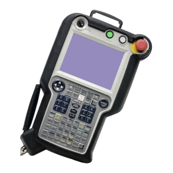
Interface panel function
MOTOMAN-NX100
Upon receipt of this product and prior to initial
operation, read these instructions thoroughly,
and retain for future reference.
© 2006 MOTOMAN Robotics Europe AB · Reg No.: MRS6036EN.0.U
Advertisement

Related Manuals for YASKAWA Motoman-NX100


Summary of Contents for YASKAWA Motoman-NX100
- Page 1 Interface panel function MOTOMAN-NX100 Upon receipt of this product and prior to initial operation, read these instructions thoroughly, and retain for future reference. © 2006 MOTOMAN Robotics Europe AB · Reg No.: MRS6036EN.0.U...
- Page 2 Reference list This manual is a revised version of the YEC document: HW0482596.4 Revision 2007-04-24 First release of this manual. Page 2 Revised: 07-04-24 Controller_front.fm...
- Page 3 Interface panel function Outline of interface panel function Display and operations of panel screen Interface panel display .................7 Data setting and touch panel I/F instructions Setting procedure ..................14 Details on interface panel setting items ............23 Save and load of set data Editing saved data Parameters Clearing the status of signals ..............35...
- Page 4 Interface panel function Page 4 Revised: 07-04-24 MRS6036EN.0.UTOC.fm...
- Page 5 Interface panel function 1. Outline of interface panel function This function makes the system construction simple and enables the reduction of operation panel and Interlock panel (hereinafter called "I/L panel") by holding the roles of operation panel and I/L board in the programming pendant (hereinafter called "PP"). Users can construct the arbitrary operation panel for PP by setting data in Interface panel set- ting screen.
- Page 6 Interface panel function Page 6 Revised: 07-04-24 MRS6036EN-ch1.fm...
- Page 7 Interface panel function Interface panel display 2. Display and operations of panel screen 2.1 Interface panel display Panel screen display Follow the operations as below to display the Interface panel. Operation Explanation EDIT DISPLAY UTILITY JOB CONTENT FD/CF JOB NAME MOTOMAN STEP NO DOUT MOVE...
- Page 8 Interface panel function Interface panel display Panel screen operation by touch panel Follow the operations as below to perform ON/OFF operation on the panel screen by touch panel. Operation Explanation DATA EDIT DISPLAY UTILITY OPERATION I/F PANEL PROH PERM PROH PERM Panel 1 Panel 2 Panel 3...
- Page 9 Interface panel function Interface panel display Information! Set the following parameter to "1" to allow operations only by the touch panel (prohibiting the operations by cursor key). Parameter: S2C301 (IF panel operation by cursor key) 0: Enable, 1: Disable Numeric display Follow the operations as below to display numeric values on the panel screen.
- Page 10 Interface panel function Interface panel display Change of panel screen Follow the operations as below to change the file number of interface panel. There are two ways of changing file number. Operation Explanation The panel page changes one by one in the forward direction. GO BACK GO BACK Press the page key...
- Page 11 Interface panel function Interface panel display Information! Unless panel names are set in each language mode, the panel names will not be displayed when the screen is changed to the subject language mode. In such a case, set the panel names in the subject language mode. MRS6036EN-ch2.fm Revised: 07-04-24 Page 11...
- Page 12 Interface panel function Interface panel display Page 12 Revised: 07-04-24 MRS6036EN-ch2.fm...
- Page 13 Interface panel function 3. Data setting and touch panel I/F instructions Set the security level to "Management" mode. Follow the operations as below to open I/F panel setting screen. Operation Explanation DATA EDIT DISPLAY UTILITY SECURITY FD/CF DOUT MOVE MANAGEMENT MODE MODE VERSION ARC WELDING...
- Page 14 Interface panel function Setting procedure 3.1 Setting procedure The following describe the process on how to set up based on the table “Example of I/F panel setting” on page 14. Example of I/F panel setting Items Set data Arrangement Setup Valid Counter Panel type...
- Page 15 Interface panel function Setting procedure I/F panel setting data and display position Operation Explanation The arrangement setting screen appears. An item with an asterisk "*" indicates that the item has already been set (the setting is enabled). DATA EDIT DISPLAY UTILITY ARRANGE SELECT GROUP NAME...
- Page 16 Interface panel function Setting procedure Editing of setup Operation Explanation The status of "SETUP" switches between "VALID" and "INVALID" with each pressing of [SELECT]. If the items "INPUT (DISP)" and "OUTPUT (SETUP)" in the I/F panel setting screen are not set, the status of "SETUP" cannot be set to "VALID".
- Page 17 Interface panel function Setting procedure Editing of panel color Operation Explanation The list of panel colors is displayed. DATA EDIT DISPLAY UTILITY I/F PANEL SETUP GROUP NAME Panel 1 ARRANGE BLACK BLUE SETUP GREEN PANEL TYPE INDICATION ONL Move the cursor to the item "PANEL SKY BLUE PANEL COLOR COLOR"...
- Page 18 Interface panel function Setting procedure Editing of text color Operation Explanation The list of text colors is displayed. DISPLAY DATA EDIT UTILITY I/F PANEL SETUP GROUP NAME Panel 1 ARRANGE BLACK BLUE SETUP GREEN PANEL TYPE INDICATION ONL Move the cursor to the item "TEXT SKY BLUE PANEL COLOR COLOR"...
- Page 19 Interface panel function Setting procedure Editing of interlock enable Operation Explanation The status of INTERLOCK ENABLE switches between "PROHIBIT" and "PERMIT" with each pressing of [SELECT]. DATA EDIT DISPLAY UTILITY I/F PANEL SETUP GROUP NAME Panel 1 ARRANGE Move the cursor to the item SETUP INVALID PANEL TYPE...
- Page 20 Interface panel function Setting procedure Editing of group name Operation Explanation DATA EDIT DISPLAY UTILITY I/F PANEL SETUP GROUP NAME DOUT GROUP NAME PANEL 1 MOVE ARRANGE PARAMETER ARC WELDING SETUP VALID PANEL TYPE SELECTOR SW LEFT ON PANEL COLOR DARK RED Select {EDIT} from the menu on the SETUP...
- Page 21 Interface panel function Setting procedure Operation Explanation The new group name is displayed in the I/F panel setting screen. DATA EDIT DISPLAY UTILITY OPERATION I/F PANEL PROH PERM PROH PERM MAIN PANEL Panel 2 Panel 3 Panel 4 Panel 5 STOP WATER STOP WATER WELD ON...
- Page 22 Interface panel function Setting procedure Operation Explanation DATA EDIT DISPLAY UTILITY I/F PANEL SETUP FD/CF DOUT GROUP NAME MAIN PANEL MOVE ARRANGE PARAMETER ARC WELDING SETUP VALID PANEL TYPE SELECTOR SW LEFT ON Select {Initialize file}. PANEL COLOR DARK RED SETUP VARIABLE PANEL NAME...
- Page 23 Interface panel function Details on interface panel setting items 3.2 Details on interface panel setting items The following describe details on the setting items of the Interface panel screen. Refer to them as required when setting the Interface panel data. Data of each setting items Items Explanations...
- Page 24 Interface panel function Details on interface panel setting items Data of each setting items Items Explanations 0: Invalid, 1: I/O, 2: B-variable, 3: I-variable, 4: Register Numbers differ according to the ID. Input (See the table “Input/output allocation status” on page 25) OFF: A-contact, ON: B-contact Contact The setting is invalid when the ID is not set to general input/output.
- Page 25 Interface panel function Details on interface panel setting items See the following table "Input/output allocation status " when allocating input/output signals. Input/output allocation status Input Output Items Range Icon type allocation allocation General #00010 to #01287 Circle/Square indication light enable disable input (1024 signals)
- Page 26 Interface panel function Details on interface panel setting items The following table "Touch panel I/F" describes the the buttons corresponding to icon types. See the table when setting icon types. Touch panel I/F Items Icon Icon type Indicates the status of allocated signals. 0, 1, 2 Circle indication light The light turns on when the status of input...
- Page 27 Interface panel function Details on interface panel setting items Touch panel I/F Items Icon Icon type Indicates the allocated variables or registers. 16, 17, Counter (3 digits) 18, 19 Counter (6 digits) * The BG color of the preset counter is white.
- Page 28 Interface panel function Details on interface panel setting items Page 28 Revised: 07-04-24 MRS6036EN-ch3.fm...
- Page 29 Interface panel function 4. Save and load of set data Set the security level to "Management" mode. (See “Editing of security” on page 18) Operation Explanation Select {FD/PC CARD} under the main menu. Select {SAVE} or {LOAD}. Move the cursor to "SYSTEM DATA"...
- Page 30 Interface panel function Page 30 Revised: 07-04-24 MRS6036EN-ch4.fm...
- Page 31 Interface panel function 5. Editing saved data The following explain how to modify the data which is saved in FD/PC CARD on PC. <Data example> //IFPANEL 1 //NAME Panel 1, Panel 1 1A,0,0,0,1,NAME1,NAME2,NAME3,1,1,0,11111,0,0,0,0,0,0,0,NAME1,NAME2,NAME3,0 1B,1,0,0,1,NAME1,NAME2,NAME3,1,1,0,11111,0,0,22222,1,0,0,0,NAME1,NAME2,NAME3,0 1C,1,0,0,1,,NAME2,,1,1,0,11111,0,0,22222,1,0,0,0,NAME1,NAME2,NAME3,0 //IFPANEL 10 ///NAME Panel 10, Panel 10 4G,0,0,0,1,NAME1,NAME2,NAME3,1,1,0,11111,0,0,0,0,0,0,0,NAME1,NAME2,NAME3,0 4H,1,0,0,1,NAME1,NAME2,NAME3,1,1,0,11111,0,0,22222,1,0,0,0,NAME1,NAME2,NAME3,0 <Details on each data items>...
- Page 32 Interface panel function 13: Square indication light3 (display only) 14: Square indication light3 (push button) 15: Square indication light3 (push-lock/push-release button) 16: Counter (3-digit display) 17: Counter (6-digit display) 18: Preset counter (3-digit display) 19: Preset counter (6-digit display) <D4>: Panel color 0: Black 1: Blue 2: Green 3: Sky blue 4: Red 5: Purple 6: Yellow 7: White 8: Light gray 9: Dark blue 10: Dark green 11: Dark sky blue 12: Dark red 13: Dark purple 14: Dark yellow 15: Dark gray 16: Orange...
- Page 33 Interface panel function Warning! Syntax error will occur when inserting line feeds into the data "Data example". Syntax error will occur when the number of commas differs from the saved data in FD/ PC card. Define capital letters for variables. Wrong signal range or type instruction will make the attribute invalid when loading.
- Page 34 Interface panel function Page 34 Revised: 07-04-24 MRS6036EN-ch5.fm...
- Page 35 Interface panel function Clearing the status of signals 6. Parameters 6.1 Clearing the status of signals By setting parameters, input/output signals at the time of power supply ON or mode change can be set to "hold" or "clear". The possible settings and the timing of status signal settings are as follows: Timing of setting the Signals Parameters...
- Page 36 Interface panel function Clearing the status of signals Status of general output signals at power supply ON By setting parameter S2C187, it allows to set the status of general output signals (#10010 to #11287) at the time of when turning the power supply ON. For the parameter setting, refer to the table below.
- Page 37 Interface panel function Allocation of general input signals to interface panel screens Status of I/F panel signals at power supply ON By setting parameters from S4C330 to S4C333, it allows to set the status of I/F panel signals (#60010 to #60647) at the time of when turning the power supply ON. For the parameter set- tings, refer to the table below.
- Page 38 Interface panel function Allocation of general input signals to interface panel screens Notification of the status of general input signals Operation Explanation When the general input signal set to the parameter turns ON, the Interface panel gets activated automatically and the corresponding panel screen appears.
- Page 39 Notes...
- Page 40 MOTOMAN Group companies: RISTRO d.o.o. Lepovce 23, SI-1310 Ribnica, Slovenia MOTOMAN robotec GmbH Phone: +386-61-8372410 Am concorde Park 1, B6/108-110, MOTOMAN Robotics UK Ltd AT-2320 Schwechat-Wien, Austria Phone +43-1-707-9324-15 Johnson Park, Wildmere Road, Banbury, Oxon OX16 3JU, Great Britain MOTOMAN robotec Czech s.r.o. Phone: +44-1295-272755 Jeremiasova 1422/7b, CZ-155 00 Prague, Czech Republic Phone +420-251-618-430...
Need help?
Do you have a question about the Motoman-NX100 and is the answer not in the manual?
Questions and answers