Table of Contents
Advertisement
Quick Links
Advertisement
Table of Contents
Troubleshooting

Related Manuals for Vanner BRAVO 1800


Summary of Contents for Vanner BRAVO 1800
- Page 2 V A N N E R I N C OR P OR A T E D Bravo 1800 – Owner’s Ma nual VANNER INCORPORATED Corporate Office: 4282 Reynolds Drive Hilliard, Ohio 43026 Tel (614) 771-2718 Fax (614)771-4904 1-800- AC POWER BRAVO 1800- OWNER’S MANUAL 9/00 ©Copyright 2000, Vanner, Inc. OM/D96523 REV.D. 01/2018...
-
Page 3: Table Of Contents
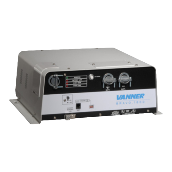
V A N N E R I N C OR P OR A T E D Bravo 1800 – Owner’s Ma nual Table of Contents Section 1 Introduction ........................1 Section 2 System Operation Section 2A Product Variations ................1 Section 2B Control Panel ................ - Page 4 V A N N E R I N C OR P OR A T E D Bravo 1800 – Owner’s Ma nual List of Figures and Tables Section 2 System Operation Figure 1 Bravo 1800 inverter/Charger Illustration ..........Table 1 Bravo 1800 Product Models ............
-
Page 5: Introduction
Section 2: System Operation Product Variations We have designed the Bravo 1800 inverter product line to meet the requirements of a variety of applications. In order to meet these requirements, we offer different models based upon the following variations: Inverter-only or Inverter with Battery Charger and AC Transfer Switch ... -
Page 6: Section 2B Control Panel
V A N N E R I N C OR P OR A T E D Bravo 1800 – Owner’s Ma nual Control Panel General Description The Control Panel contains LED (light emitting diode) indicators and switches that you will need to use when installing and operating your inverter system. - Page 7 V A N N E R I N C OR P OR A T E D Bravo 1800 – Owner’s Ma nual System On/Off Switch The On/Off Switch allows you to control the operation of the inverter and battery WARNING charger.
- Page 8 V A N N E R I N C OR P OR A T E D Bravo 1800 – Owner’s Ma nual LED Indicators A set of LED (Light Emitting Diode) indicators are provided to display the status of the inverter system. Six LEDs are provided on inverter/charger models and four are provided on inverter-only models.
- Page 9 V A N N E R I N C OR P OR A T E D Bravo 1800 – Owner’s Ma nual Remote Panel –P/N DO5039 Table 3-LED Status Indicators Inverter Light Action Description Steady Green Light Inverter is On Inverter circuit is Off.
-
Page 10: Section 2C Wiring Panel
V A N N E R I N C OR P OR A T E D Bravo 1800 – Owner’s Ma nual 2C) Wiring Panel General Description The wiring Panel where all field wiring is connected to the inverter. For wall mounted enclosures this panel is located on the inverter's bottom surface. -
Page 11: Section 2D Theory Of Operation
V A N N E R I N C OR P OR A T E D Bravo 1800 – Owner’s Ma nual 2D) Theory of Operation Inverter Overview In general, an inverter converts DC electrical power into AC power. This power can be used to operate various AC driven appliances. -
Page 12: Section 2E Inverter Sizing
V A N N E R I N C OR P OR A T E D Bravo 1800 – Owner’s Ma nual 2E) Inverter Sizing Power Output Rating Power output is an important consideration when selecting an inverter. Power is defined as the rate that a device produces (or uses) electrical energy. -
Page 13: Section 2F Battery Charger Option
Bravo 1800 – Owner’s Ma nual 2F) Battery Charger Option The Bravo 1800 Battery Charger's advanced design incorporates an automatic, multistage charger. This design enables the unit to automatically charge batteries, maintaining the battery's integrity and reducing the likelihood of premature failure. The battery charger is designed to be used with lead-add type batteries including sealed and gel types, but not for nickel-cadmium (Ni-Cad) or nickel-iron types. -
Page 14: Section 2G Automatic Ac Power Transfer
V A N N E R I N C OR P OR A T E D Bravo 1800 – Owner’s Ma nual Guidelines for Battery Charging Warning The following information on battery charger setup adjustments should be used as guidelines only. -
Page 15: Section 3A Unpacking The Inverter
V A N N E R I N C OR P OR A T E D Bravo 1800 – Owner’s Ma nual SECTION 3: INSTALLATION Unpacking the Inverter Inspect the shipping container and equipment for loose or damaged parts. If any damage is found, immediately notify the freight carrier. - Page 16 V A N N E R I N C OR P OR A T E D Bravo 1800 – Owner’s Ma nual E. Route the AC and DC power wiring separately, and with as much physical separation as possible, from low voltage wiring such as audio and video signal wires.
- Page 17 V A N N E R I N C OR P OR A T E D Bravo 1800 – Owner’s Ma nual AC Wiring—Model BR12-1800SG This inverter-only model is provided with a GFCI duplex receptacle for its AC output. Ground Fault Current Interrupter Protection Some installations require the installation of Ground Fault Circuit Interrupter (GFCI) type circuit breakers in the AC distribution system.
-
Page 18: Section 3C Remote Panels
V A N N E R I N C OR P OR A T E D Bravo 1800 – Owner’s Ma nual C) Strip the two (positive and negative) DC cable ends 3/4 in. D) Insert the black, negative (-) cable end through the strain relief and into the negative terminal lug. -
Page 19: Section 3D System Start-Up And Testing
V A N N E R I N C OR P OR A T E D Bravo 1800 – Owner’s Ma nual 3D) System Start-up and Testing Step 1 Completely install the unit following the instructions provided in Section 4—System Design Considerations and Section 3—Inverter Installation. -
Page 20: System Design Considerations
V A N N E R I N C OR P OR A T E D Bravo 1800 – Owner’s Ma nual inverter to shore power. The inverter LED should change from solid to blinking and become solid. *Step 19: Test the battery charger operation by first discharging the battery. -
Page 21: Section 4B Battery Types And Ratings
V A N N E R I N C OR P OR A T E D Bravo 1800 – Owner’s Ma nual What is the DC current draw of a 12 volt DC input inverter Example A: when it is operating a vacuum cleaner with a name plate rating of... -
Page 22: Section 4C Sizing The Inverter Battery
V A N N E R I N C OR P OR A T E D Bravo 1800 – Owner’s Ma nual Operating temperature: A battery becomes less efficient at lower temperatures. Most battery manufacturers specify the battery A-H capacity at 80°F. At a temperature of 32°F, the same battery will have only about 65% of its rated capacity even though it may be fully charged. -
Page 23: Section 4D Dc Charging Systems
V A N N E R I N C OR P OR A T E D Bravo 1800 – Owner’s Ma nual 4D) DC Charging Systems The DC charging system is a very important part of your inverter installation. The... -
Page 24: Section 4E Inverter Applications
V A N N E R I N C OR P OR A T E D Bravo 1800 – Owner’s Ma nual Inverter Applications There are many different ways that an inverter can be installed and is probably only limited by ones imagination and wiring codes. There are only a few types which we will convey to you that use good engineering practices and will cover most needs in a recreational or service vehicle. -
Page 25: Bravo 1800 Specifications
V A N N E R I N C OR P OR A T E D Bravo 1800 – Owner’s Ma nual Section 5: Bravo 1800 Specifications BRAVO INVERTERS INVERTER CHARGERS INVERT MODEL # BR12-1800SH BR12-1800SG BRC12-1800SH BRC12-1800WH BRC24-1800WH BRC12-800WH/EX... -
Page 26: Maintenance & Troubleshooting
Bravo 1800 – Owner’s Ma nual SECTION 6: MAINTENANCE & TROUBLESHOOTING 6A) Preventative Maintenance There are no user serviceable components inside these inverters. For service refer to Vanner Inc. or other qualified service personnel. 6B) Maintenance Items For continued reliability and safety, a monthly maintenance program should be implemented to include the following: Check to insure that all external wiring is secure and corrosion free. -
Page 27: Section 6C Troubleshooting Procedures
V A N N E R I N C OR P OR A T E D Bravo 1800 – Owner’s Ma nual 6C) Troubleshooting Procedures The following are the most common questions heard by Vanner service professionals. If your situation does not apply to the following categories, please contact your local Vanner Inc. Service Center. -
Page 28: Gfci Test Record
V A N N E R I N C OR P OR A T E D Bravo 1800 – Owner’s Ma nual Section 7: GFCI Test Record For maximum protection against electrical shock hazard, operate the Test Switch on the Ground Fault Circuit Interrupter at least once a month. -
Page 29: Warranty
The product was purchased after January 1, 2000. Vanner does not warrant its products against any and all defects when: defect is a result of material or workmanship not provided by Vanner; normal wear and tear, or defects caused by misuse or use in contrary to instructions supplied, neglect, accident, reversed polarity, unauthorized repairs and/or replacements.
Need help?
Do you have a question about the BRAVO 1800 and is the answer not in the manual?
Questions and answers