Extron electronics VSW 2VGA A User Manual
Hide thumbs
Also See for VSW 2VGA A:
- User manual (40 pages) ,
- Specifications (2 pages) ,
- Setup manual (2 pages)
Table of Contents
Advertisement
Quick Links
Download this manual
See also:
User Manual
VSW 2VGA A • User Guide
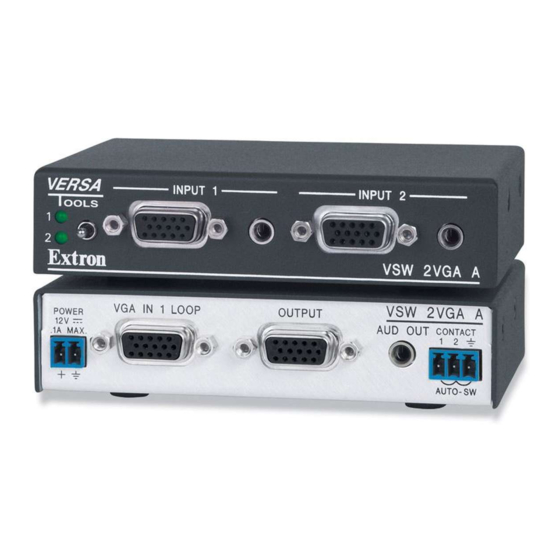
The Extron VSW 2VGA A is a compact and economical two-input, one-output VGA
switcher with unbalanced stereo audio and 300 MHz (-3 dB) video bandwidth. It
accepts two VGA-UXGA, RGBHV, RGBS, RGsB, RsGsBs, component video, or
HDTV component video inputs. The switcher has two unbalanced stereo audio
inputs and one unbalanced stereo audio output. It also features a buffered local
monitor output for Input 1. A front panel toggle switch, a contact closure controller,
or the autoswitching option can be used for input selection.
This guide contains information about the Extron VSW 2VGA A switcher. The
terms "VSW 2VGA A" and "switcher" are used interchangeably in this manual.
The Extron VSW I AAP interface, an optional accessory used when several
VSW 2VGA A switchers are daisy chained together, is also discussed.
FCC Class A Notice
This equipment has been tested and found to comply with the limits for a Class A digital device, pursuant to part 15 of the
FCC rules. The Class A limits provide reasonable protection against harmful interference when the equipment is operated in a
commercial environment. This equipment generates, uses, and can radiate radio frequency energy and, if not installed and used
in accordance with the instruction manual, may cause harmful interference to radio communications. Operation of this equipment
in a residential area is likely to cause interference. This interference must be corrected at the expense of the user.
NOTES:
•
This unit was tested with shielded
compliance with FCC emissions limits.
•
For more information on safety guidelines, regulatory compliances, EMI/EMF compatibility, accessibility, and related
topics, see the
Specifications
Product specifications are available on the Extron website, www.extron.com.
Application Diagram
Up to 10 VSW 2VGA A switchers can be daisy chained
together with each switcher input separately fed and
controlled by an optional accessory interface, the VSW I AAP.
Figure 1 is an example of how several such switcher-interface
combinations can be daisy chained together in a boardroom
environment.
By default, all switchers are set to input 2 as the active input.
Therefore, in a daisy chain of switchers the VGA and audio
signals flow from one switcher to input 2 of the next switcher
in the chain. The switchers are daisy chained in this fashion
until the last switcher in the daisy chain outputs to a projector
and audio amplifier.
Up to ten switchers can be daisy chained together without
any degradation in picture quality. One power supply powers
up to five switchers.
I/O c
ables on the peripheral devices. Shielded cables must be used to ensure
Extron Safety and Regulatory Compliance Guide
on the Extron website.
Projector
Extron
VSW I AAP
Extron
VSW 2VGA A
VGA Switcher
COMPUTER
AUDIO
SHOW ME
VSW I AAP
Extron
Expandable, economical presentation chain for
VSW I AAP
conference rooms and library study rooms.
VSW I AAP
VSW I AAP
In 1
In 2
In 2
Out
VSW 2VGA A
VSW 2VGA A
Extron pre-made VGA with audio cable assemblies.
Figure 1.
Daisy Chaining the Multiple Switchers
Projector
VSW I AAP
In 1
In 1
In 2
Out
Out
VSW 2VGA A
1
Advertisement
Table of Contents

Related Manuals for Extron electronics VSW 2VGA A


Summary of Contents for Extron electronics VSW 2VGA A
-
Page 1: Specifications
Extron and audio amplifier. VSW 2VGA A VGA Switcher Up to ten switchers can be daisy chained together without any degradation in picture quality. One power supply powers up to five switchers. -
Page 2: Installation Overview
Check the cabling and make adjustments as needed. Select a different input to check for a picture and sound. Front Panel Features INPUT 1 INPUT 2 VSW 2VGA A VSW 2VGA A Front Panel Features Figure 2. Input 1 LED indicator — This LED lights green whenever Input 1 (video and audio) is selected. -
Page 3: Rear Panel Features
Input 2 video — Input VGA-UXGA, RGBHV, RGBS, RGsB, RsGsBs, component video, or HDTV component video through this female 15-pin VGA connector. Input 2 audio— Input unbalanced stereo audio through this 3.5 mm mini audio jack (see figure 3). Rear Panel Features VSW 2VGA A POWER VGA IN 1 LOOP OUTPUT... -
Page 4: Setting The Vsw 2Vga A Jumpers
VSW 2VGA A • User Guide (Continued) Autoswitching — • NOTES: • Autoswitch mode must be disabled when daisy chaining VSW 2VGA A switchers. If the autoswitch mode is enabled, the switchers cannot be daisy chained. • RGsB and RsGsBs inputs and outputs occur in manual mode only. •... -
Page 5: Power Connnection
VSW 2VGA A • User Guide (Continued) Pin 5 - Show Me Pin 9 - Power OPEN CLOSED Input 1 JMP 1 All jumpers are set open (disabled) by default. Input 2 JMP 3 JMP 4 Open or close the indicated jumpers in the table, Output JMP 5 JMP 6... -
Page 6: Operation
VSW 2VGA A • User Guide (Continued) ATTENTION: • Always use a power supply supplied by or specified by Extron. Use of an unauthorized power supply voids all regulatory compliance certification and may cause damage to the supply and the end product. •... -
Page 7: Single Switcher Example
A jumper on the VSW I AAP may need to be shifted from jumper J6 (the default position) to J5, depending on the application (see figure 10). J5 J6 Jumper installed Switcher compatibility VSW 2VGA A (Input 1) VSW 2VGA A (Input 2) Figure 10. VSW I AAP Jumpers Single switcher example Figure 11 shows an example of a single switcher configuration. -
Page 8: Loop Configuration Example
INPUT 1 INPUT 2 INPUT 1 INPUT 2 INPUT 1 INPUT 2 INPUT 1 INPUT 2 VSW 2VGA A VSW 2VGA A VSW 2VGA A VSW 2VGA A VSW 2VGA A VSW 2VGA A VSW 2VGA A VSW 2VGA A... -
Page 9: Mounting The Vsw 2Vga A
Input 2 Closed Closed JMP3 JMP3 INPUT 1 INPUT 2 INPUT 1 INPUT 2 JMP4 Closed JMP4 Closed VSW 2VGA A VSW 2VGA A Closed Open JMP5 JMP5 JMP6 Closed JMP6 Open 12 V Power Supply* NOTE: * Every switcher connected to Input 1 of another switcher must have its own power supply. -
Page 10: Rack Mounting Instructions
VSW 2VGA A • User Guide (Continued) Reliable earthing (grounding) — Maintain reliable grounding of rack-mounted equipment. Pay particular attention to supply connections other than direct connections to the branch circuit (e.g. use of power strips). 1inchQuarterRackShelf Rack mounting instructions If feet were installed on the bottom of the switcher, remove them. Mount the VSW 2VGA A on a rack shelf. -
Page 11: Under-Desk Mounting
VSW 2VGA A • User Guide (Continued) Under-desk mounting Attach the under-desk mounting brackets to the VSW 2VGA A with the four provided machine screws, as shown in figure 16. Hold the switcher with attached brackets against the mounting surface. Use a soft pencil to mark the location of holes for screws on the desk or other furniture. - Page 12 VSW 2VGA A • User Guide (Continued) www.extron.com © 2007-2018 Extron Electronics All rights reserved. All trademarks mentioned are the property of their respective owners. 68-1111-01 Rev. E 10 18...
Need help?
Do you have a question about the VSW 2VGA A and is the answer not in the manual?
Questions and answers