
Related Manuals for TLV JH7RH-B


Summary of Contents for TLV JH7RH-B
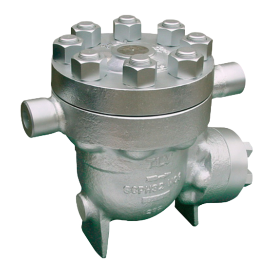
- Page 1 172-65440MA-01 (JH7RH-B) 18 November 2020 Free Float Steam Trap JH7RH-B Copyright © 2020 by TLV CO., LTD. All rights reserved...
-
Page 2: Table Of Contents
Product Warranty ............15 Options ................16 Introduction Thank you for purchasing the TLV free float steam trap. This product has been thoroughly inspected before being shipped from the factory. When the product is delivered, before doing anything else, check the specifications and external appearance to make sure nothing is out of the ordinary. -
Page 3: Safety Considerations
The three types of cautionary items above are very important for safety: be sure to observe all of them as they relate to installation, use, maintenance, and repair. Furthermore, TLV accepts no responsibility for any accidents or damage occurring as a result of failure to observe these precautions. - Page 4 Use only under conditions in which no water hammer will occur. The impact of water hammer may damage the product, leading to fluid discharge, which may cause burns or other injury. 172-65440MA-01(JH7RH-B) 18 Nov 2020...
-
Page 5: Checking The Piping
4. Have maintenance valves been installed at the inlet and outlet? If the outlet is subject to back pressure, has a check valve (TLV-CK) been installed? 5. Is the inlet pipe as short as possible, with as few bends as possible, and installed so the liquid will flow naturally down into the trap? 6. -
Page 6: Operation
4. Closed Position When the condensate flow rate decreases, the float falls, closing off the orifice (B) opening. A water seal is maintained at all times over the orifice (B) to prevent steam loss. Steam Condensate 172-65440MA-01(JH7RH-B) 18 Nov 2020... -
Page 7: Specifications
25 Snap Ring * Replacement parts are available only in the following kits: 26 Air Vent Guide Gasket M = Maintenance Kit; R = Repair Kit; F = Float 27 Air Vent Guide 172-65440MA-01(JH7RH-B) 18 Nov 2020... -
Page 8: Installation
6. Open the inlet and outlet valves and ensure that the product functions properly. If there is a problem, determine the cause using the “Troubleshooting” section in this manual. Tolerance Angle for Installation: 5° Make sure the trap is installed with the raised TLV lettering on the body horizontal. 172-65440MA-01(JH7RH-B) 18 Nov 2020... -
Page 9: Maintenance
Check for clogging or corrosion Bimetal Plate: Check for damage Air Vent Valve (and Seat): Check for damage Float: Check for scratches or dents Body Interior: Check for build-up Orifice Opening: Check for dirt, oil film, wear or scratches 172-65440MA-01(JH7RH-B) 18 Nov 2020... -
Page 10: Disassembly/Reassembly
Air Vent Guide Remove the gasket and Replace with a new gasket Gasket clean sealing surfaces *When disassembly is not required, the entire unit may be removed and replaced at the Air Vent Guide with an open wrench. 172-65440MA-01(JH7RH-B) 18 Nov 2020... - Page 11 4. Hold it in that position by hand and, after hand-tightening the orifice locknut from the outlet side, hold the orifice in place from the body float chamber side using a drive wrench and then tighten the orifice locknut to the proper torque using a torque wrench. 172-65440MA-01(JH7RH-B) 18 Nov 2020...
- Page 12 2. Using the tightening torques for the cover nuts and outlet cover nuts as a reference, tighten until the cover and outlet cover gaps are uniform. The gaps should be 1.5 mm ( in) or less. Cover or Outlet Cover 1.5 mm ( Body 172-65440MA-01(JH7RH-B) 18 Nov 2020...
- Page 13 Orifice Locknut Outlet Cover Gasket Outlet Cover Outlet Cover Nut Air Vent Guide Gasket Air Vent Guide Air Vent Case Air Vent Valve Plug Snap Ring Air Vent Air Vent Screen Valve Seat Snap Ring Bimetal Plate 172-65440MA-01(JH7RH-B) 18 Nov 2020...
-
Page 14: Instructions For Plug/Holder Disassembly And Reassembly
Instructions for Plug/Holder Disassembly and Reassembly The seal on the threaded plugs/holders found on TLV products is formed by a flat metal gasket. There are various installation orientations for the gaskets, such as horizontal, diagonal and downward, and the gasket may be pinched in the thread recesses during assembly. -
Page 15: Troubleshooting
NOTE: When replacing parts with new, use the parts list for reference, and replace with parts from the Maintenance Kit, Repair Kit, etc. Please note that replacement parts are only available as part of a replacement parts kit. 172-65440MA-01(JH7RH-B) 18 Nov 2020... -
Page 16: Product Warranty
One year following product delivery. 2. Warranty Coverage TLV CO., LTD. warrants this product to the original purchaser to be free from defective materials and workmanship. Under this warranty, the product will be repaired or replaced at our option, without charge for parts or labor. -
Page 17: Options
The options shown below are available for this product on request. Please compare with the product you received. Options for Area A (standard: without drain plug) With Drain Plug Torque Distance Across Flats Nm (lbf·ft) (in) (73) 30 (1 (1 Nm 10 kgcm) 172-65440MA-01(JH7RH-B) 18 Nov 2020...
Need help?
Do you have a question about the JH7RH-B and is the answer not in the manual?
Questions and answers