Table of Contents
Advertisement
Quick Links
Advertisement
Table of Contents

Related Manuals for Bosch PowerBox PBX 190


Summary of Contents for Bosch PowerBox PBX 190
- Page 1 PowerBox PBX 190 Manual 1 07/02/2019...
-
Page 2: Table Of Contents
Content Content 1 About PowerBox PBX 190 ............................. 2 Hardware ..................................Ventilation ..........................................Status LEDs..........................................Pin Configuration........................................Supply Concept ........................................48 V Stages ..........................................Current measurement......................................G-Sensors ..........................................Warnings and shutdown Thresholds ................................3 PBX Suite Installation ..............................4 The Structure Editor: Create a new configuration ...................... -
Page 3: About Powerbox Pbx 190
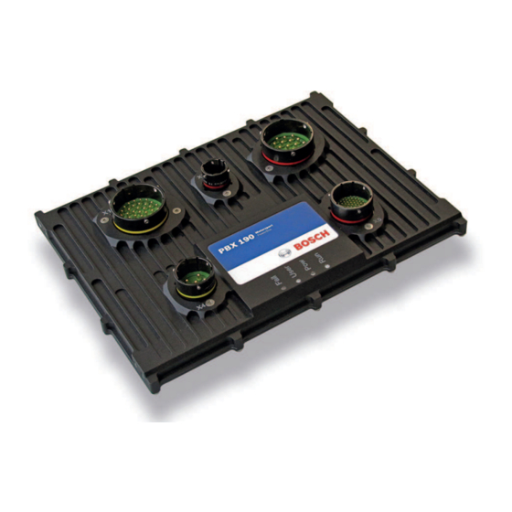
Bosch PowerBox PBX 190 is a compact and light weight module, measuring 245 x 183 x 37 mm (including connectors). -
Page 4: Hardware
2 | Hardware 2 Hardware The Bosch PowerBox PBX 190 enclosure is CNC machined to the highest standards. The two parts of the casing are sealed by an O-ring, located in a recess in the main half. A lip in the lid presses on the O-ring and assures a water tight sealing (IP67). The connectors are individually sealed. -
Page 5: Pin Configuration
HS_15A X1_b 1 PWM_15A X1_c 1 PWM_15A X1_d 1 PWM_15A X1_e 1 PWM_15A X1_f 1 HS_15A X1_g 1 HS_15A X1_h 1 HS_15A X1_k 1 HS_15A X1_m 1 HS_15A X1_n 1 Power KL31 Power KL31 Power KL31 Bosch Motorsport PowerBox_PBX_190_Manual 5 / 40... - Page 6 0 to 5 V, Pull-up CAN 3 Interface Low-Level Max. 1 Mbaud Analog Input X5_10 0 to 5 V, Pull-up Analog Input X5_11 0 to 5 V, Pull-up Analog Input X5_12 0 to 5 V, Pull-up 6 / 40 PowerBox_PBX_190_Manual Bosch Motorsport...
- Page 7 0 to 12 V, Pull-up, Pull-down Digital Input X5_14 0 to 12 V, Pull-up, Pull-down CAN 3 Interface High-Level Max. 1 Mbaud Control of Bosch Motorsport LIN devices included. Support of other devices on request. Analog Input X5_17 0 to 5 V, Pull-up...
-
Page 8: Supply Concept
SENS-GND-1 (X5_45) and SENS-GND-2 (X5_52) are the reference ground of these sensor supply voltages. Use these two ground pins preferred for analog sensor reference. For digital inputs ground reference pins X5_19 and X5_20 can be used. 8 / 40 PowerBox_PBX_190_Manual Bosch Motorsport... -
Page 9: Stages
It is recommended to use an external fuse when using 48 V to be safe in case of a shortcut to GND. For details using 48 V in PBX 190 please contact Bosch Motorsport. 2.6 Current measurement Each Output stage has its own shunt resistor to measure the output current. -
Page 10: G-Sensors
Shutdown overcurrent over GND Pins on X1 and 80 A for 2 s Overtemperatur Warning overtemperature CPU 95°C for 2 s Shutdown overtemperature CPU 100°C for 2 s Warning overtemperature Device 95°C for 2 s Shutdown overtemperature Device 115°C for 2 s 10 / 40 PowerBox_PBX_190_Manual Bosch Motorsport... -
Page 11: Pbx Suite Installation
PBX Suite Installation | 3 3 PBX Suite Installation The setup file for the PBX Suite is provided at the Bosch Motorsport internet homepage at the product page of the PowerBox PBX 190. For the PBX Suite a personal license key is required. This can be requested at order time of a PowerBox PBX 190 device or later by mail to LicenseMotorsport.BEG@de.bosch.com... -
Page 12: The Structure Editor: Create A New Configuration
A configuration is the unit you exchange between the programming tool PBX Suite and your PowerBox PBX 190 after all changes and modifications. For creating a configuration we developed the PBX Suite. This software tool enables visual programming of the configuration of your PowerBox. - Page 13 The function block CAN_Input is available as data type Boolean or data type Integer or data type Float. To separate one from the other we put a letter at the end of the function blocks name: Bosch Motorsport PowerBox_PBX_190_Manual 13 / 40...
-
Page 14: Utilities For Placing And Arranging Of Function Blocks
– red for outputs blue green 4.2 Utilities for placing and arranging of Function Blocks At the Layout tab – Rulers and Grid can be enabled or disabled, – several functions helping to align the Function Blocks are available. 14 / 40 PowerBox_PBX_190_Manual Bosch Motorsport... -
Page 15: Navigating Through The Configuration
Click Structure Editor in the menu box on the left side. Click New. Select your PBX Type. Load the corresponding PST File. Confirm by clicking OK. Write Input in the text field of the Catalogue [Insert here all words to filter, use “;” as separator]. Bosch Motorsport PowerBox_PBX_190_Manual 15 / 40... - Page 16 10. The assigned connector and pin are part of the function blocks name shown in the headline of the function block. Here it is X5_10, as you can see in the following screen shot. Notice: All function blocks can be renamed by changing the name in Properties / Name. 16 / 40 PowerBox_PBX_190_Manual Bosch Motorsport...
- Page 17 12. Drag and Drop the function OneDLookuptable from the Catalogue onto the screen. If you want to see the actual temperature in the Live Data later, please enable the OneDLookupTable by setting Y to enabled (red ring). Therefore you click on the or- Bosch Motorsport PowerBox_PBX_190_Manual 17 / 40...
- Page 18 13. For more information about Live Data, please see View Live Data [} 30]. 14. Double-click on the function OneDLookuptable opens a curve and a table where you can fill in your sensor data. 15. Write hyst in the text field of the Catalogue. 18 / 40 PowerBox_PBX_190_Manual Bosch Motorsport...
- Page 19 It changes color to red when activated. Sign in the value 90.0 as De- faultValue under Properties as shown in the following screenshot. 18. Set 10.0 as DefaultValue under Hyst in the same function block. Bosch Motorsport PowerBox_PBX_190_Manual 19 / 40...
- Page 20 The HS_25 function block will pop up as shown in the following screenshot. 21. With double-click on the selected function block you open the pin assignment wizard. Select Output X3_B from the pull down menu, similar to step 9. 20 / 40 PowerBox_PBX_190_Manual Bosch Motorsport...
- Page 21 Congratulations! You have programmed your first function! Further steps After creating the configuration, you got the following options: – transfer and activate the configuration to the PowerBox PBX 190 with PowerBox Man- ager, – follow the signal values with PowerBox Manager, –...
-
Page 22: Structuring Of Complex Configurations
Right click on a selected function block to open the context menu Select Create Container A Container block appears which is connected to the environment. In the properties tab a description, an image or an alternative name can be setup. 22 / 40 PowerBox_PBX_190_Manual Bosch Motorsport... - Page 23 Navigation to the outside is done in the lower left corner. A further outside connection can be generated by Right clicking on an in- or output port, Select Add Connector to Container. Bosch Motorsport PowerBox_PBX_190_Manual 23 / 40...
-
Page 24: Utilities For Navigating Through Complex Configurations
Protecting a configuration with a password can be done by clicking the Button ‘Save with password protection‘. Enter the password and confirm it. From now on the correct password has to be entered to open this configuration. 24 / 40 PowerBox_PBX_190_Manual Bosch Motorsport... -
Page 25: First Upload Of A Configuration
Start your PBX Suite and activate the PowerBox Manager by clicking on the button as shown in the following screenshot: After a short while the screen will show your device: Now you can transfer the config file. Therefore right-click on the device window and choose Send Config and Start: Bosch Motorsport PowerBox_PBX_190_Manual 25 / 40... - Page 26 Choose the configuration file which you want to put on your PowerBox. In this ex- ample it is named Primeconfig.cfg. Confirm with click on Open. The config file was put on the PowerBox, and after an automatically restart the device window shows the name of the configuration: 26 / 40 PowerBox_PBX_190_Manual Bosch Motorsport...
-
Page 27: Update Of An Existing Configuration
6 Update of an existing configuration This chapter will show how to update a configuration. Click Project Configuration on Catalogue tab as shown in the following picture. Select the corresponding PST file. Confirm by clicking OK. Bosch Motorsport PowerBox_PBX_190_Manual 27 / 40... -
Page 28: The Powerbox Manager
This chapter will show how to switch between different configurations on your PowerBox. Right mouse click on the device window will open the menu as shown in the following screenshot. Click on Stop to end the active configuration. Click Start to choose the new configuration. 28 / 40 PowerBox_PBX_190_Manual Bosch Motorsport... - Page 29 The Powerbox Manager | 7 Choose the new configuration from the pull down menu, here “Secondconfig.cfg”. Confirm with click on Start. The device will restart and after a short time the device window shows the name of the second configuration. Bosch Motorsport PowerBox_PBX_190_Manual 29 / 40...
-
Page 30: View Live Data
For output ports the current value is shown, some with additional Description information. For input ports it is possible to affect the operative value. The result is controlled by the selected PoolingMode. Various support for filtering the amount of data is provided, including the support for Lay- ers. 30 / 40 PowerBox_PBX_190_Manual Bosch Motorsport... -
Page 31: Error Log
In the context menu select „View Error Log“ to view the error log entries. Besides the location and type further information are available. To clear the error log, click „Clear Error Log“ in the upper left corner of the error log win- dow. Bosch Motorsport PowerBox_PBX_190_Manual 31 / 40... -
Page 32: Integration To Racecon
At the same location the Configuration is saved, an additional export file for RaceCon is written. It is suffixed by an ‚_A‘ or ‚_B‘ and the extension is ‚PRG‘: Drag & Drop a PowerBox PBX 190 in RaceCon into the project and select this ‚PRG‘ file if asked for the program archive:... - Page 33 Integration to RaceCon | 8 Bosch Motorsport PowerBox_PBX_190_Manual 33 / 40...
-
Page 34: Faq
9 | FAQ 9 FAQ You’ll find an FAQ list on the PowerBox product site of bosch-motorsport.com. 34 / 40 PowerBox_PBX_190_Manual Bosch Motorsport... -
Page 35: Disposal
Hardware, accessories and packaging should be sorted for recycling in an environment- friendly manner. Do not dispose of this electronic device in your household waste. Waste electronic equipment must be disposed of properly according to Electrical and Electronics Act (ElektroG) and the European WEE directive. Bosch Motorsport PowerBox_PBX_190_Manual 35 / 40... -
Page 36: Technical Specifications
<1 A continuously Maximum recommended output current 250 A continuously; >310 A peak current (2 Communication Ethernet Control of Bosch Motorsport LIN devices included. Support of other devices on re- quest. Real time ethernet Sercos (optional) Inputs 18 analogue inputs (16 bit resolution) switchable pull-up resistors... - Page 37 Bosch Motorsport PowerBox_PBX_190_Manual 37 / 40...
- Page 38 38 / 40 PowerBox_PBX_190_Manual Bosch Motorsport...
- Page 39 Bosch Motorsport PowerBox_PBX_190_Manual 39 / 40...
- Page 40 Bosch Engineering GmbH Motorsport Robert-Bosch-Allee 1 74232 Abstatt Germany www.bosch-motorsport.com...
Need help?
Do you have a question about the PowerBox PBX 190 and is the answer not in the manual?
Questions and answers