Table of Contents
Advertisement
MITSUBISHI ELECTRIC PRE-PLUMBED UNVENTED MAINS PRESSURE WATER HEATER
WITH FTC5 CONTROL SYSTEM FOR USE WITH THE ECODAN
AIR SOURCE HEAT PUMP RANGE
150, 170, 210, 250 and 300 LITRE CAPACITY STANDARD MODELS
210, 250 and 300 LITRE CAPACITY SOLAR MODELS
150 and 170 LITRE CAPACITY SLIMLINE MODELS
INSTALLATION AND SERVICING INSTRUCTIONS
IMPORTANT: PLEASE READ AND UNDERSTAND THESE INSTRUCTIONS
BEFORE COMMENCING INSTALLATION. PLEASE LEAVE THIS MANUAL
WITH THE CUSTOMER FOR FUTURE REFERENCE.
1
Advertisement
Table of Contents

Related Manuals for Ecodan 150 Standard


Summary of Contents for Ecodan 150 Standard
- Page 1 MITSUBISHI ELECTRIC PRE-PLUMBED UNVENTED MAINS PRESSURE WATER HEATER WITH FTC5 CONTROL SYSTEM FOR USE WITH THE ECODAN AIR SOURCE HEAT PUMP RANGE 150, 170, 210, 250 and 300 LITRE CAPACITY STANDARD MODELS 210, 250 and 300 LITRE CAPACITY SOLAR MODELS...
-
Page 2: Table Of Contents
INTRODUCTION This range of factory pre-plumbed and wired unvented water heaters specifically designed for use with the Mitsubishi Ecodan Air Source Heat Pump range. The cylinder is manufactured in the UK from top quality materials and meets all the latest relevant safety and constructional standards. - Page 3 3 months of commissioning and ensure they benefit from the applicable standard guarantee for their Ecodan heat pump and any cylinder or interfacing equipment purchased from Mitsubishi Electric by you as installer. The guarantee applies where the installation address is in England, Scotland or Wales only and for domestic use.
-
Page 4: General Requirements
GENERAL REQUIREMENTS IMPORTANT: THIS APPLIANCE CAN BE USED BY CHILDREN AGED FROM 8 YEARS AND ABOVE AND PERSONS WITH REDUCED PHYSICAL SENSORY OR MENTAL CAPABILITIES OR LACK OF EXPERIENCE AND KNOWLEDGE IF THEY HAVE BEEN GIVEN SUPERVISORY OR INSTRUCTION CONCERNING USE OF THE APPLIANCE IN A SAFE WAY AND UNDERSTAND THE HAZARDS INVOLVED. - Page 5 OUTLET/TERMINAL FITTINGS (TAPS, ETC.) The Pre-plumbed cylinder can be used in conjunction with most types of terminal fittings, plumbing fittings and pipework. However, the rated pressures of any fittings selected should be checked for compatibility before installation. NOTE: Accessories, plumbing fittings and pipework should have a rated operating pressure of at least 8 bar. Outlets situated higher than the cylinder will give outlet pressures lower than that at the unit, a 10m height difference will result in a 1 bar pressure reduction at the outlet fitting.
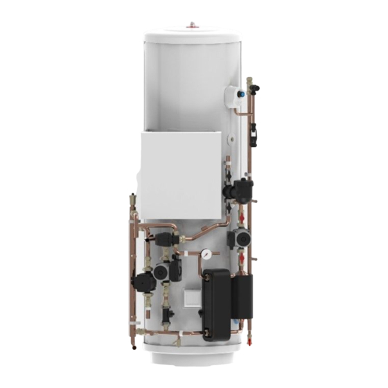
- Page 6 Fig 1 - Parts identification Hot Water Outlet Magnetic lter FTC5 Controller Expansion Valve Automatic Air Vent Temperature/Pressure Low loss header Relief Valve Tundish 3 Way motorised diverter valve DHW circulating Primary circuit pump pressure gauge Expansion vessel tapping Primary circulation pumps Scale Trap Immersion heater...
- Page 7 1256 1508 1760 2074 1050 1175 1385 1123 1437 MODEL 150 Standard 170 Standard 210 Standard 250 Standard 300 Standard Energy efficiency class Standing loss in W Storage volume V in Litres Technical parameters in accordance with European Commission regulations 814/2013 and 812/2013...
- Page 8 Fig 2b - Dimensions and EU Product Fiche - Solar models OVERALL HEIGHT HEAT PUMP FLOW CONNECTION (22mm O/D COPPER) TUNDISH OUTLET CONNECTION (22mm COMPRESSION) HEAT PUMP RETURN CONNECTION (22mm O/D COPPER) HEATING CIRCUIT FLOW CONNECTION (22mm O/D COPPER) HEATING CIRCUIT RETURN CONNECTION (22mm O/D COPPER) SOLAR COIL CONNECTIONS (22mm COMPRESSION / 3/4”...
- Page 9 Fig 2c - Dimensions and EU Product Fiche- Slimline models OVERALL HEIGHT HEAT PUMP FLOW CONNECTION (22mm O/D COPPER) TUNDISH OUTLET CONNECTION (22mm COMPRESSION) HEAT PUMP RETURN CONNECTION (22mm O/D COPPER) HEATING CIRCUIT FLOW CONNECTION (22mm O/D COPPER) HEATING CIRCUIT RETURN CONNECTION (22mm O/D COPPER) COLD WATER INLET CONNECTION (22mm COMPRESSION) HOT WATER OUTLET CONNECTION (22mm COMPRESSION / 3/4”...
- Page 10 Table 2 - STANDARD Cylinder Technical Data...
- Page 11 Table 3 - SOLAR Cylinder Technical Data...
- Page 12 Table 4 - SLIMLINE Cylinder Technical Data...
- Page 13 Setting up the UPM3 pump When you switch on the pump it will run to the pre-set position or the last setting. The diagram below shows the current operation status. To change the pump setting, follow below: (a) Press the ‘ ’ to switch to the settings view. The LEDs show the current setting for2 seconds. (b) Release ‘...
- Page 14 • PP1: lowest proportional Control Mode explanation pressure curve Proportional pressure • PP2: Intermediate The head pressure is reduced at falling heat demand proportional pressure and increased at rising heat demand. The duty point of the circulator will move up or down on curve the selected proportional pressure curve depending on the heat demand in the system.
- Page 15 Graph 2 - UPM GEO performance curve Graph 3 - UPMXL GEO performance curve...
-
Page 16: Installation – General
INSTALLATION – GENERAL PIPE FITTINGS The connection points to the heating system are in 22mm copper pipe. The use of appropriately sized COMPRESSION FITTINGS is recommended when connecting to the pipes. Solder fittings can be used, but extreme care must be taken to ensure any anciallry components in close proximity are not damaged by heat. - Page 17 DRAIN TAPS Drain taps are fitted to both the primary system pipework and to the cold water inlet to facilitate draining the unit or indirect heating circuit for maintenance purposes. It is recommended that the outlet point of the drain pipe work be at least 1 metre below the level of the heater (this can be achieved by attaching a hose pipe to the drain tap outlet spigot).
- Page 18 Fig 7 - Schematic installation diagram...
-
Page 19: Installation - Discharge
INSTALLATION - DISCHARGE It is a requirement of Building Regulation G3 that any discharge from an unvented system is conveyed to where it is visible, but will not cause danger to persons in or about the building. The tundish and discharge pipes should be fitted in accordance with the requirements and guidance notes of Building Regulation G3. - Page 20 Note: An alternative approach for sizing discharge pipes would be to follow Annex D, section D.2 of BS 6700:2006 Specification for design, installation, testing and maintenance of services supplying water for domestic use within buildings and their curtilages. 3.59 Where a single common discharge pipe serves more than one system, it should be at least one pipe size larger than the largest individual discharge pipe(D2) to be connected.
- Page 21 Table 5 - Sizing of copper discharge pipe (D2) for common temperature relief valve outlet sizes MAXIMUM RESISTANCE ALLOWED, MINIMUM SIZE OF MINIMUM SIZE OF RESISTANCE EXPRESSED AS VALVE OUTLET SIZE DISCHARGE PIPE DISCHARGE PIPE CREATED BY EACH A LENGTH OF D2 FROM TUNDISH ELBOW OR BEND STRAIGHT PIPE (i.e.
-
Page 22: Installation - Heat Pump Primary Circuit
INSTALLATION - HEAT PUMP PRIMARY CIRCUIT HEAT PUMP SELECTION • The Pre-plumbed cylinders are suitable for use with the Mitsubishi Electric Ecodan Air Source heat pumps listed in Table 6 below • If in doubt consult Mitsubishi Electric for further advice. - Page 23 MAIN CONTROLLER FLOW RATE LOOK UP The main controller can now show you the flow rates by using Request Code 540 in the Service Menu (see FTC5 main manual). WIRING All electrical wiring should be carried out by a competent electrician and be in accordance with the latest I.E.E. Wiring Regulations.
- Page 24 Fig 11 - 2 zone control pack - temperature sensor wiring Primary Flow Secondary Z1 Flow TB1.2 3-4 (THW6) Secondary Z2 Flow TB1.2 7-8 (THW8) TB1.2 9-10 (THW9) Secondary Z2 Return TB1.2 5-6 (THW7) Primary Return Secondary Z1 Return Fig 12 - 2 zone control pack - dip switch settings SW2-7 - ON SW3-6 - ON...
- Page 25 Fig 13 - Optional 2 zone twin temperature control pack - plumbing schematic Fig 14 - Optional 2 zone twin temperature control pack - component wiring TBO.1 3-4 (OUT2) Mixing Valve Secondary Z1 Flow Secondary Z2 Flow TBO.1 5-6 (OUT3) TBO.2 1-2-3 (OUT5) Secondary Z2 Return Secondary Z1 Return...
- Page 26 Fig 15 - Optional 2 zone twin temperature control pack - sensor wiring TB1.2 3-4 (THW6) Mixing Valve Secondary Z1 Flow Secondary Z2 Flow TB1.2 7-8 (THW8) TB1.2 9-10 (THW9) Secondary Z2 Return TB1.2 5-6 (THW7) Secondary Z1 Return Fig 16 - Optional 2 zone twin temperature control pack - dip switch settings SW2-7 - ON...
- Page 27 Fig 17 - Wiring of Motorised Mixing valve Fig 18 - Schematic of Motorised Mixing Valve hydraulic connections BLUE TO RIGHT HAND DHW PUMP PRIMARY PUMP BROWN CONNECTION TO PCB BY MEANS OF BLUE TO LEFT HAND RED JST PLUG PRIMARY PUMP CONNECTOR TO BROWN...
- Page 30 How to use TB0 1 to 5...
-
Page 31: Installation - Solar Primary
INSTALLATION - SOLAR PRIMARY CONNECTION TO THE SOLAR PRIMARY CIRCUIT The lower coil of the Solar models must be connected to a fully pumped solar primary circuit. The connections are suitable for a 22mm copper pipe direct to compression fittings provided. The connections are also threaded 3/4” BSP male parallel should BSP connections be required. -
Page 32: Installation - Immersion Heater Electrical Supply
INSTALLATION - IMMERSION HEATER ELECTRICAL SUPPLY The pre-plumbed cylinder units are supplied fitted with an immersion heater which can be used to supplement the Air Source Heat Pump heating input. The immersion heater is located within the controls housing. Refer to Fig 21 below for details of wiring of the immersion heater. -
Page 33: Commissioning
COMMISSIONING At the time of commissioning, please ensure a Commissioning Checklist is completed for the installation. FILLING THE UNIT WITH WATER • BEFORE FILLING CHECK AND TIGHTEN ALL MECHANICAL JOINTS AND CONNECTIONS IN CASE THESE HAVE LOOSENED DURING TRANSIT. • Check expansion vessel pre-charge pressure. -
Page 34: Maintenance
MAINTENANCE MAINTENANCE REQUIREMENTS Unvented hot water systems have a continuing maintenance requirement in order to ensure safe working and optimum performance. It is essential that the relief valve(s) are periodically inspected and manually opened to ensure no blockage has occurred in the valves or discharge pipework. Similarly cleaning of the strainer element and replacement of the air in the expansion vessel will help to prevent possible operational faults. - Page 35 CLEANING THE FERNOX TF-1 COMPACT MAGNETIC FILTER Note: There is no need to remove the cap of the TF-1 filter for cleaning Close the isolating valves either side of the TF-1 magnetic filter. Remove the magnetic core by pulling upwards. Wait 30 seconds for any collected particles to settle in the filter body.
-
Page 36: Fault Finding & Servicing
FAULT FINDING & SERVICING IMPORTANT • After servicing, complete the relevant Service Interval Record for the installation. • Servicing should only be carried out by competent persons in the installation and maintenance of unvented water heating systems. • Any spare parts used MUST be authorised Mitsubishi Electric parts. •... - Page 37 Table 8 - Spares list DESCRIPTION PART NO. Immersion heater (including terminal shroud and gasket) 95602002 Immersion heater gasket 95611026 Immersion heater backnut 95605204 Immersion heater key spanner 95605205 Tundish 95607881 Expansion Valve Cartridge 8 bar 95605206 Expansion Valve 8 bar Complete 95605207 Temperature / pressure relief valve 95605209...
- Page 38 Fig 23 - Spares Diagram Fig 24 - Pressure Reducing valve 3.5 bar Fig 25 - Element spares Cold Mains Connection (22mm) Outlet Connection (22mm)
-
Page 39: User Instructions
USER INSTRUCTIONS WARNINGS IF WATER ISSUES FROM THE TEMPERATURE/PRESSURE RELIEF VALVE ON THE PRE-PLUMBED CYLINDER, SHUT DOWN THE HEAT PUMP AND IMMERSION HEATER. DO NOT TURN OFF ANY WATER SUPPLY. CONTACT A COMPETENT INSTALLER FOR UNVENTED WATER HEATERS TO CHECK THE SYSTEM. DO NOT TAMPER WITH ANY OF THE SAFETY VALVES FITTED TO THE PRE-PLUMBED CYLINDER. -
Page 40: Environmental Information
ENVIRONMENTAL INFORMATION Products are manufactured from many recyclable materials. At the end of their useful life they should be disposed of at a Local Authority Recycling Centre in order to realise the full environmental benefits. Insulation is by means of an approved CFC/HCFC free polyurethane foam with an ozone depletion factor of zero. WEEE Declaration Disposal of Waste Equipment by Users in Private Household in the European Union.
Need help?
Do you have a question about the 150 Standard and is the answer not in the manual?
Questions and answers