Table of Contents
Advertisement
PRE-PLUMBED UNVENTED MAINS PRESSURE
WATER HEATER WITH FTC6 CONTROL SYSTEM.
FOR USE WITH ECODAN PUZ-(H)WM
AIR SOURCE HEAT PUMP RANGE.
SERVICE MANUAL
EHPT15X-UKHLDW1S
EHPT17X-UKHLDW1S
EHPT15X-UKHDW1S
EHPT17X-UKHDW1S
EHPT21X-UKHDW1S
EHPT21X-UKHDW1L
EHPT25X-UKHDW1L
EHPT30X-UKHDW1L
IMPORTANT: PLEASE READ AND UNDERSTAND THESE INSTRUCTIONS
PLEASE LEAVE THIS MANUAL WITH THE CUSTOMER FOR FUTURE REFERNCE.
BEFORE PERFORMING ANY MAINTENANCE.
Renewable Heating Technology
January 2022
Doc. No. 607483
Advertisement
Table of Contents

Related Manuals for Ecodan EHPT15X-UKHLDW1S


Summary of Contents for Ecodan EHPT15X-UKHLDW1S
- Page 1 Renewable Heating Technology PRE-PLUMBED UNVENTED MAINS PRESSURE WATER HEATER WITH FTC6 CONTROL SYSTEM. January 2022 FOR USE WITH ECODAN PUZ-(H)WM AIR SOURCE HEAT PUMP RANGE. Doc. No. 607483 SERVICE MANUAL EHPT15X-UKHLDW1S EHPT17X-UKHLDW1S EHPT15X-UKHDW1S EHPT17X-UKHDW1S EHPT21X-UKHDW1S EHPT21X-UKHDW1L EHPT25X-UKHDW1L EHPT30X-UKHDW1L IMPORTANT: PLEASE READ AND UNDERSTAND THESE INSTRUCTIONS BEFORE PERFORMING ANY MAINTENANCE.
-
Page 2: Table Of Contents
CONTENTS REFERENCE MANUAL ........................3 SAFETY PRECAUTION........................4 SPECIFICATIONS ..........................6 PART NAMES AND FUNCTIONS .......................8 OUTLINES AND DIMENSIONS ......................9 WIRING DIAGRAM ..........................13 FIELD WIRING .............................15 WATER SYSTEM DIAGRAM ......................16 CONTROLS............................19 TROUBLESHOOTING.........................40 DISASSEMBLY PROCEDURE......................SUPPLEMENTARY INFORMATION ....................57 SERVICE AND MAINTENANCE ......................58 ENVIRONMENTAL INFORMATION ....................68 TECHNICAL SUPPORT ........................68... -
Page 3: Reference Manual
REFERENCE MANUAL OUTDOOR UNIT'S SERVICE MANUAL Service Ref. Service Manual No. PUZ-WM50VHA(-BS).UK PUZ-WM60VAA(-BS).UK PUZ-WM85VAA(-BS).UK OCH727 PUZ-WM85YAA(-BS).UK OCB727 PUZ-WM112VAA(-BS).UK Packaged model PUZ-WM112YAA(-BS).UK PUZ-HWM140VHA(-BS) OCH748 PUZ-HWM140YHA(-BS) OCB748... -
Page 4: Safety Precaution
SAFETY PRECAUTION Please read the following safety precautions carefully. WARNING: CAUTION: Precautions that must be observed to prevent injuries or death. Precautions that must be observed to prevent damage to unit. • Be sure to perform periodical maintenance. • Be sure to follow your local regulations. •... - Page 5 CAUTION Use clean water that meets local quality standards on the primary circuit. The cylinder unit should be located inside to minimise heat loss. Water pipe-runs on the primary circuit between outdoor and indoor unit should be kept to a minimum to reduce heat loss. Ensure condensate from outdoor unit is piped away from the base to avoid puddles of water.
-
Page 6: Specifications
SPECIFICATIONS... -
Page 8: Part Names And Functions
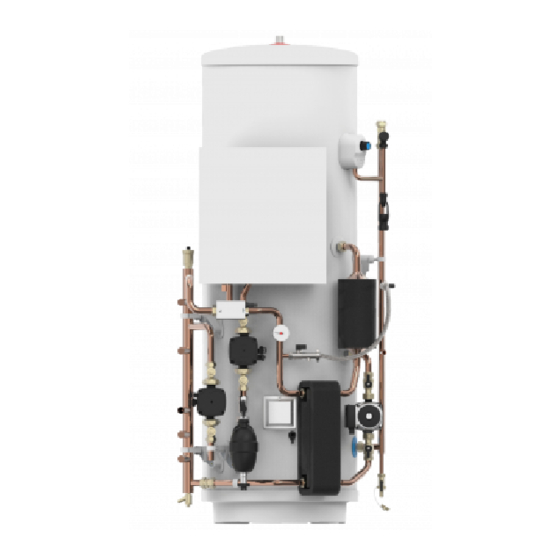
PART NAMES AND FUNCTIONS Hot Water Outlet FTC6 Controller Flow sensor (behind controller) Expansion Valve Temperature/Pressure Relief Valve Automatic Air Vent THW5A thermistor boss Tundish Low loss header 3 Way motorised Scale Trap diverter valve Primary circuit pressure gauge Expansion vessel tapping Heat Pump circulating pump... -
Page 9: Outlines And Dimensions
OUTLINES AND DIMENSIONS Dimensions - 28mm Standard Models C & E OVERALL HEIGHT SECONDARY RETURN TAPPING HEAT PUMP FLOW CONNECTION (28mm O/D COPPER) TUNDISH OUTLET CONNECTION (22mm COMPRESSION) HEAT PUMP RETURN CONNECTION (28mm O/D COPPER) HEATING ZONE 1 CIRCUIT FLOW CONNECTION (22mm O/D COPPER) HEATING ZONE 1 CIRCUIT RETURN CONNECTION (22mm O/D COPPER) COLD WATER INLET CONNECTION (22mm COMPRESSION) HOT WATER OUTLET CONNECTION (22mm COMPRESSION / 3/4”... - Page 10 Dimensions - 22mm Standard Models C & E OVERALL HEIGHT SECONDARY RETURN TAPPING (NOT FITTED TO EHPT15X-UKHDW1S/ EHPT17X-UKHDW1S) HEAT PUMP FLOW CONNECTION (22mm O/D COPPER) TUNDISH OUTLET CONNECTION (22mm COMPRESSION) HEAT PUMP RETURN CONNECTION (22mm O/D COPPER) HEATING ZONE 1 CIRCUIT FLOW CONNECTION (22mm O/D COPPER) HEATING ZONE 1 CIRCUIT RETURN CONNECTION (22mm O/D COPPER) COLD WATER INLET CONNECTION (22mm COMPRESSION) HOT WATER OUTLET CONNECTION (22mm COMPRESSION / 3/4”...
- Page 11 Dimensions - 22mm Slimline Models B & D OVERALL HEIGHT HEAT PUMP FLOW CONNECTION (22mm O/D COPPER) TUNDISH OUTLET CONNECTION (22mm COMPRESSION) HEAT PUMP RETURN CONNECTION (22mm O/D COPPER) HEATING ZONE 1 CIRCUIT FLOW CONNECTION (22mm O/D COPPER) HEATING ZONE 1 CIRCUIT RETURN CONNECTION (22mm O/D COPPER) COLD WATER INLET CONNECTION (22mm COMPRESSION) HOT WATER OUTLET CONNECTION (22mm COMPRESSION / 3/4”...
- Page 12 Please allow sufficient clearance at the front to close a door where fitted. Sufficient space MUST be left for the provision of discharge pipework as detailed in National and Local Building Regulations. Dimensions of A, B & C in above diagram Dimension Model EHPT15X-UKHLDW1S 976mm 972mm 268mm EHPT17X-UKHLDW1S EHPT15X-UKHDW1S 1030mm...
-
Page 13: Wiring Diagram
WIRING DIAGRAM... - Page 14 DIP Switch Functions Located on the FTC printed circuit board are 6 sets of small white switches known as DIP switches. The DIP switch number is printed on the circuit board next to the relevant switches. The word ON is printed on the circuit board and on the DIP switch block itself.
-
Page 15: Field Wiring
FIELD WIRING FTC (Master) powered by independent source If FTC (Master) and outdoor units have separate power supplies, the following requirements MUST be carried out: • FTC (Master) unit electrical box connector connections changed. Black Initial settings CNO1 • Outdoor unit DIP switch settings changed to SW8-3 ON. (Power supplied •... -
Page 16: Water System Diagram
WATER SYSTEM DIAGRAM... - Page 17 Local System Optional 2 zone control pack - plumbing schematic Zone1 Zone2 Optional 2 zone twin temperature control pack - plumbing schematic Zone1 Zone2...
- Page 18 Filling The Cylinder CYLINDER UNIT - INITIAL FILL PROCEDURE • BEFORE FILLING CHECK AND TIGHTEN ALL MECHANICAL JOINTS AND CONNECTIONS IN CASE THESE HAVE LOOSENED DURING TRANSIT. • Check expansion vessel pre-charge pressure. The vessel is supplied pre-charged to 3.5 bar to match the control pressure of the pressure reducing valve.
-
Page 19: Controls
CONTROLS Main remote controller <Main remote controller parts> Letter Name Function To change the settings of your heating/cooling system please use the main Screen Screen in which all information is displayed remote controller located on the front panel of the cylinder unit or hydrobox. Menu Access to system settings for initial set up and The following is a guide to viewing the main settings. - Page 20 Setting the Main remote controller After the power has been connected to the outdoor and cylinder units (See "7. FIELD WIRING"), the initial system settings can be entered via the main remote con- troller. 1. Check all breakers and other safety devices are correctly installed and turn on power to the system. setting screen in order.
- Page 21 <Main Remote Controller Menu Tree> Initial Unrestricted access Installer only Main screen * Short press for 1 Zone system. Long press Information Option Forced DHW ON ( )/OFF ON ( )/Prohibited ( )/Timer ( ) Heating/Cooling ON ( )/Prohibited ( )/Timer ( ) Energy monitor Consumed electrical energy Menu...
- Page 22 <Continued from the previous page.> <Main Controller Menu Tree> Unrestricted access Initial Installer only Main screen Main menu Long press Manual operation Menu Function settings Service Thermistor adjustment Password ON/OFF protected Economy settings for pump Delay ON/OFF Electric heater (Heating) Delay ON/OFF (Booster heater/Immersion heater) Auxiliary settings...
- Page 23 <Continued from the previous page.> <Main Controller Menu Tree> Unrestricted access Initial Installer only Main screen Main menu Long press Menu Booster heater 1 capacity Electric heater Booster heater 2 capacity capacity Immersion heater Analog output Pump 1 Energy monitor Water pump input Pump 2 settings...
- Page 24 Service Menu The service menu provides functions for use by installer or service engineer. It is NOT intended the home owner alters settings within this menu. It is for this reason password protection is required to prevent unauthorised access to the service settings. The factory default password is "0000".
- Page 25 <Thermistor adjustment> This function allows adjustments to be made to the thermistor readings from −10 to 10°C in 0.5°C intervals. THW1: Thermistor (Flow water temp.) THW2: Thermistor (Return water temp.) THW5: Thermistor (DHW tank water temp.) THW6: THW7: Thermistor (Zone1 return temp.)(Option) THW8: THW9: Thermistor (Zone2 return temp.)(Option) THW10: Thermistor (Mixing tank temp.)(Option)
- Page 26 Mixing valve control 1. From the Auxiliary settings menu highlight Mixing valve control. 2. Press CONFIRM. 3. The Mixing valve control screen is displayed. 4. Use F1 and F2 buttons to set Running time between 10 to 240 seconds. The Running time equals to a period from full open of the valve (at a hot water mixing ratio of 100%) to full close (at a cold water mixing ratio of 100%).
- Page 27 <Operation settings> Heating operation adaptation mode. Menu subtitle Function Range Unit Default Flow temp. range Minimum temp. To minimize the loss by frequent ON and OFF in mild outdoor ambient tem- 20 to 45 ºC perature seasons. Maximum temp. 35 to 60 ºC Room temp.
- Page 28 <Energy monitor settings> 1. General description End user can monitor accumulated( ) ‘Consumed electrical energy’ and ‘Delivered heat energy’ in each operation mode( ) on the main remote controller. Monthly and Year to date - DHW operation - Space heating - Space cooling Refer to the menu tree in “Main Settings Menu”...
- Page 29 2. Settings using the main remote controller In this menu, all parameters required to record the consumed electrical energy and the delivered heat energy which is displayed on the main remote controller can be set. The parameters are an electric heater capacity, supply power of water pump and heat meter pulse.
- Page 30 <Summary of settings> This function shows the current installer/user entered settings. Abbreviation Explanation Abbreviation Explanation HWtemp Z2 mode DHW max. temperature Operation mode HWdrop DHW temperature drop - HER (Heating room temperature) HWtime DHW max. operation time - HE (Heating flow temperature) NO HW DHW mode restriction - HCC (Heating compensation curve)
- Page 31 4. Choose either Manual Reset for FTC or Main remote controller. <SD card> *Ecodan service tool (for use with PC tool) is necessary for the setting. Main RC 1. From the SD card setting use F1 and F2 buttons to scroll through list until “SD...
- Page 32 Request Request content Range Unit code Error history 1 (latest) Displays error history. ("– –" is displays if no history is present.) Code Error history 2 (second to last) Displays error history. ("– –" is displays if no history is present.) —...
- Page 33 Indoor unit switch setting display (Request code: 162 to 166) 0: OFF 1: ON 0: OFF 1: ON SW1, SW2, SW3, SW4, SW5 SW1, SW2, SW3, SW4, SW5 Display Display 00 00 00 40 00 01 00 41 00 02 00 42 00 03 00 43...
- Page 34 Indoor unit switch setting display (Request code: 162 to 166) 0: OFF 1: ON 0: OFF 1: ON SW1, SW2, SW3, SW4, SW5 SW1, SW2, SW3, SW4, SW5 Display Display 00 80 00 C0 00 81 00 C1 00 82 00 C2 00 83 00 C3...
- Page 35 Output signal display (Request code: 175/553) Please refer to Table 2 on relevant wiring diagram whilst using the following. 0: OFF 1: ON 0: OFF 1: ON Display Display xx 40 xx 00 xx 01 xx 41 xx 42 xx 02 xx 03 xx 43 xx 04...
- Page 36 Output signal display (Request code: 175/553) Please refer to Table 2 on relevant wiring diagram whilst using the following. 0: OFF 1: ON 0: OFF 1: ON Display Display xx C0 xx 80 xx C1 xx 81 xx C2 xx 82 xx C3 xx 83 xx C4...
- Page 37 0: OFF 1: ON Output signal display (Request code: 175/553) Display Please refer to Table 2 on relevant wiring diagram whilst using the following. 40 xx 41 xx 0: OFF 1: ON 42 xx 43 xx Display 44 xx 00 xx 45 xx 01 xx 46 xx...
- Page 38 Input signal display (Request code: 176/554) Please refer to Table 1 on relevant wiring diagram whilst using the following. 0: OFF (open) 1: ON (short) 0: OFF (open) 1: ON (short) Display Display 00 00 00 40 00 01 00 41 00 02 00 42 00 03...
- Page 39 Indoor unit only operation Indoor unit only operation In indoor unit only operation, an operation without connecting outdoor unit is possible. When in Indoor unit only operation, the main control has control functions. Indoor unit Necessary Heat pump Not necessary <Heater>...
-
Page 40: Troubleshooting
TROUBLESHOOTING Troubleshooting <Summary of self-diagnosis based on Check codes and Service Procedures> Present and past Check codes are logged, and they can be displayed on the main remote controller or control board of the outdoor unit. Unit Condition Check code Action Reoccurring problem Displayed... - Page 41 Self-diagnosis and action Check if DIP SW is set correctly. (Refer to "DIP switch functions".) Check code Title and display conditions Possible Cause Diagnosis and action Circulation water temperature overheat 1 Refer to table in "Checking Component protection Parts' Function" to determine if system <DHW/Heating/Cooling/LP/FS/OS>...
- Page 42 Check code Title and display conditions Possible Cause Diagnosis and action P1/P2/L5/LD Indoor unit temperature thermistor failure 1. Connector/terminal wire has become 1. Visually check the terminals and connec- Note: The thermistors subject to failure can be detached or loose wiring. tions and reattaches appropriate.
- Page 43 Check code Title and display conditions Possible Cause Diagnosis and action Heating operation error 1. THW1 has become detached from its 1. Visually inspect location and reattach as Note: “3” is displayed in “Request code: 567” in holder. necessary. “Running information”. 2.
- Page 44 Check code Title and display conditions Possible Cause Diagnosis and action 1. If more head required either add a pump of the same size or replace existing pump. 2. Check circulation pump (See "Checking Note: “3” is displayed in “Request code: 569” in Component Parts' Function"...
- Page 45 Check code Title and display conditions Possible Cause Diagnosis and action <Defrosting> <Defrosting> THW2 detects a temperature ≤15ºC and TH2 1., 2.Check water piping. detects a temperature ≤−16ºC for consecutive 10 seconds. • Leakage of water 2. Low temperature • Low load •...
- Page 46 Check code Title and display conditions Possible Cause Diagnosis and action E1/E2 Main remote controller control board failure 1. Fault with the main remote controller 1. Replace main remote controller circuit circuit board board. Check code E1 displayed if main remote control- ler cannot access it is non volatile (non power dependent) memory.
- Page 47 Troubleshooting by inferior phenomena Fault symptom Possible cause Explanation - Solution Main remote controller 1. There is no power supply to main remote 1. Check LED2 on FTC. (See "WIRING DIAGRAM".) display is blank. controller. (i) When LED2 is lit. Check for damage or contact failure of the main remote controller wiring.
- Page 48 Fault symptom Possible cause Explanation - Solution LED2 on FTC is off. <FTC powered on independent source> (See "WIRING 1. FTC is not supplied with 220 to 240 VAC. 1. Check the voltage across the L and N terminals on the indoor power supply DIAGRAM".) terminal block.
- Page 49 Fault symptom Possible cause Explanation - Solution Water heating takes 1. Heat pump not working. 1. Check heat pump – consult outdoor unit service manual. longer. 2. Booster heater cut-out tripped. 2. Check booster heater thermostat and press reset button if safe. Reset button is located on the side of booster heater, covered with white rub- 3.
- Page 50 Fault symptom Possible cause Explanation - Solution Heating system does Heating system operates depending on the heating Normal operation, no action necessary. not reach the set load to prevent low-load heating system from the lower temperature. frequent switching (ON/OFF) of the compressor. In 2-zone tempera- 1.
- Page 51 Fault symptom Possible cause Explanation - Solution Water discharges from 1. Check function of pressure reducing valve and replace if necessary. expansion relief valve valve not working. - part of Inlet Control 2. If continual – expansion relief valve may be 2.
- Page 52 Fault symptom Possible cause Explanation - Solution 1. Incorrect setting of the energy monitor 1. Check the setting by following the procedure below. 35 The energy monitor val- (1) Check if the DIP switch is set as the table below. ue seems not correct.
- Page 53 Test point diagram FTC (Controller board) CNP1/OUT1 (TBO.1 1-2) Water circulation pump1 (230 VAC) OUT2 (TBO.1 3-4) Water circulation pump2 (Local supply) (230 VAC) CN01 OUT3 (TBO.1 5-6) Power supply Water circulation pump3 (230 VAC) (Local supply) (230 VAC) CNP4/OUT14 Water circulation pump4 (230 VAC) 10 A/250 V...
- Page 54 FAULT FINDING IMPORTANT • Any required parts should be purchased from Mitsubishi Electric parts. • Disconnect the electrical supply before removing any electrical equipment covers. • NEVER bypass any thermal controls or operate system without the necessary safety valves. • Water contained in the Air Source Heat Pump pre-plumbed cylinder may be very hot, especially following a thermal control failure.
-
Page 55: Disassembly Procedure
DISASSEMBLY PROCEDURE PREPARATION FOR DISASSEMBLY ● Prepare the proper tools. ● Prepare the proper protectors. ● Provide adequate ventilation. ● After stopping the operation of the cylinder and outdoor unit, turn off all the power-supply breakers. ● Allow parts to cool. ●... - Page 56 Immersion heater supply cable Mains supply cable (L, N & ) Communication supply cable (S2 & S3) Drain valve Drain valve Wi-Fi connector 1. Turn off electrical supplies 2. Turn off cold water supply 3. Drain down Heat Pump to both Cylinder and Heat to Heat Pump Cylinder.
-
Page 57: Supplementary Information
SUPPLEMENTARY INFORMATION Back-up operation of boiler Heating operation is backed up by boiler. For more details, refer to the installation manual of PAC-TH012HT(L)-E. <Installation & System set up> 1. Set DIP-SW1-1 to ON "With boiler" and SW2-6 to ON “With Mixing tank”. 2. -
Page 58: Service And Maintenance
SERVICE AND MAINTENANCE Engineers Forms Should settings be changed from default, please enter and record new setting in ‘Field Setting’ column. This will ease resetting in the future should the system use change or the circuit board need to be replaced. Commissioning/Field settings record sheet Main remote controller screen Parameters... - Page 59 Commissioning/Field settings record sheet (continued from the previous page) Default Field Main remote controller screen Parameters Notes setting setting Setting Service Pump speed Pump speed (1 to 5) menu Heating/Cooling Pump speed (1 to 5) Heat source setting Standard/Heater/Boiler/Hybrid *11 Standard Heat pump setting Minimum(0 to 100L/min)
- Page 60 Commissioning/Field settings record sheet (continued from the previous page) Default Field Main remote controller screen Parameters Notes setting setting Service Energy Electric heater Booster heater 1 0 to 30 kW 2 kW monitor set- menu capacity capacity tings Booster heater 2 0 to 30 kW 4 kW capacity...
- Page 61 Annual Maintenance Log Book Contractor name Engineer name Site name Site number Cylinder unit maintenance record sheet Warranty number Model number Serial number Mechanical Frequency Notes Turn OFF water supply, drain DHW tank, remove mesh from strainer clean and replace in strainer. *1 Keep water supply OFF, open hot water taps and check the primary-side expansion vessel charge pressure.
- Page 62 MAINTENANCE REQUIREMENTS Unvented hot water systems have a continuing maintenance requirement in order to ensure safe working and optimum performance. It is essential that the relief valve(s) are periodically inspected and manually opened to ensure no blockage has occurred in the valves or discharge pipe work. Similarly cleaning of the strainer element and replacement of the air in the expansion vessel will help to prevent possible operational faults.
- Page 63 CLEANING THE FERNOX TF-1 SIGMA MAGNETIC FILTER To clean the filter follow the procedure as described below. If necessary, once cleaning has been completed, re-pressurise the system using the filling loop fitted to the unit. 1. Ensure the installation is not 2.
- Page 64 Isolation Valve Magnet Cap Inlet/Outlet Port Isolation Valve Filter Body Drain Valve Drain Valve Cap Fernox TF-1 Sigma Magnetic Filter assembly ANNUAL MAINTENANCE LOG BOOK On completion of any maintenance or service of the pre-plumbed cylinder, the Annual Maintenance Log Book should be filled in to record the actions taken and the date the work was undertaken.
- Page 65 Notes...
- Page 66 Notes...
- Page 67 Notes...
-
Page 68: Environmental Information
ENVIRONMENTAL INFORMATION ENVIRONMENTAL INFORMATION Products are manufactured from many recyclable materials. At the end of their useful life they should be disposed of at a Products are manufactured from many recyclable materials. At the end of their useful life they should be disposed of at a Local Authority Recycling Centre in order to realise the full environmental benefits.
Need help?
Do you have a question about the EHPT15X-UKHLDW1S and is the answer not in the manual?
Questions and answers