Table of Contents
Advertisement
Quick Links
PRE-PLUMBED UNVENTED MAINS PRESSURE
WATER HEATER WITH FTC6 CONTROL SYSTEM.
FOR USE WITH ECODAN PUZ-(H)WM
AIR SOURCE HEAT PUMP RANGE.
INSTALLATION MANUAL
EHPT15X-UKHLDW1S
EHPT17X-UKHLDW1S
EHPT15X-UKHDW1S
EHPT17X-UKHDW1S
EHPT21X-UKHDW1S
EHPT21X-UKHDW1L
EHPT25X-UKHDW1L
EHPT30X-UKHDW1L
IMPORTANT: PLEASE READ AND UNDERSTAND THESE INSTRUCTIONS
PLEASE LEAVE THIS MANUAL WITH THE CUSTOMER FOR FUTURE REFERNCE.
BEFORE COMMENCING INSTALLATION.
Renewable Heating Technology
January 2022
Doc. No. 607431
Advertisement
Table of Contents

Related Manuals for Ecodan EHPT15X-UKHLDW1S


Summary of Contents for Ecodan EHPT15X-UKHLDW1S
- Page 1 Renewable Heating Technology PRE-PLUMBED UNVENTED MAINS PRESSURE January 2022 WATER HEATER WITH FTC6 CONTROL SYSTEM. FOR USE WITH ECODAN PUZ-(H)WM Doc. No. 607431 AIR SOURCE HEAT PUMP RANGE. INSTALLATION MANUAL EHPT15X-UKHLDW1S EHPT17X-UKHLDW1S EHPT15X-UKHDW1S EHPT17X-UKHDW1S EHPT21X-UKHDW1S EHPT21X-UKHDW1L EHPT25X-UKHDW1L EHPT30X-UKHDW1L IMPORTANT: PLEASE READ AND UNDERSTAND THESE INSTRUCTIONS BEFORE COMMENCING INSTALLATION.
-
Page 2: Table Of Contents
CONTENTS SAFETY NOTICES ..........................2 INTRODUCTION...........................4 GENERAL REQUIREMENTS ......................6 INSTALLATION – GENERAL ......................18 INSTALLATION - DISCHARGE ......................21 INSTALLATION - HEAT PUMP PRIMARY CIRCUIT .................24 INSTALLATION - WI-FI ADAPTER.....................37 INSTALLATION - IMMERSION HEATER ELECTRICAL SUPPLY ..........SYSTEM SET UP..........................38 COMMISSIONING ..........................49 ENVIRONMENTAL INFORMATION ....................52 LOCAL APPLICATION FACTORS ......................52 TECHNICAL SUPPORT ........................52 SAFETY NOTICES... - Page 3 SAFETY NOTICES WARNING Mechanical The cylinder unit and outdoor unit must not be installed, disassembled, relocated, altered or repaired by the user. Ask an authorised installer or technician. If the unit is ce capable of bearing its weight. The cylinder unit should be positioned on a hard level surface nd or vibration.
-
Page 4: Introduction
NOTE: When using a sealed heating system, adequate provision for expansion within the primary circuit MUST be provided by fitting a primary circuit expansion vessel. Primary circuit expansion cannot be accommodated within the Air Source Heat Pump cylinder. A primary circuit pressure relief valve is fitted within the Ecodan PUZ-(H)WM air source heat pump outdoor unit. - Page 5 3 months of commissioning and ensure they benefit from the applicable standard guarantee for their Ecodan heat pump and any cylinder or interfacing equipment purchased from Mitsubishi Electric by you as installer. The guarantee applies where the installation address is in England, Scotland or Wales only and for domestic use.
-
Page 6: General Requirements
GENERAL REQUIREMENTS IMPORTANT: THIS APPLIANCE CAN BE USED BY CHILDREN AGED FROM 8 YEARS AND ABOVE AND PERSONS WITH REDUCED PHYSICAL SENSORY OR MENTAL CAPABILITIES OR LACK OF EXPERIENCE AND KNOWLEDGE IF THEY HAVE BEEN GIVEN SUPERVISORY OR INSTRUCTION CONCERNING USE OF THE APPLIANCE IN A SAFE WAY AND UNDERSTAND THE HAZARDS INVOLVED. - Page 7 IMPORTANT INSTALLATION NOTE WHERE THE INLET SUPPLY TO THE PRESSURE REDUCING VALVE (PRV) IS ROUTED THROUGH A HEATED SPACE AND IS FITTED WITH A CHECK VALVE OR OTHER FITTING THAT WOULD PREVENT BACK FLOW, HIGH PRESSURES CAN BE EXPERIENCED IN THE INLET PIPE DUE TO WARMING THAT CAN CAUSE DAMAGE TO THE PRV OR OTHER FITTINGS ON THE INLET SUPPLY.
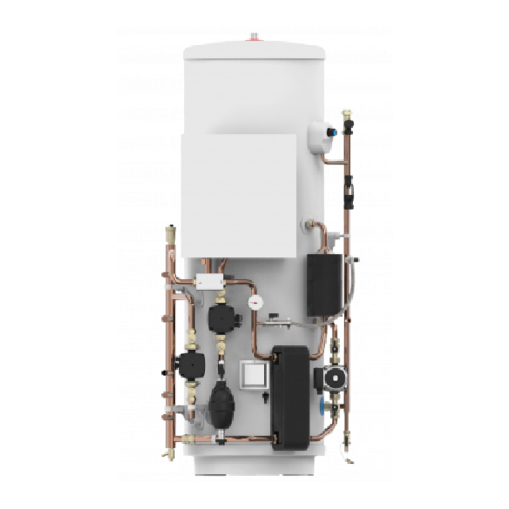
- Page 8 Fig. 1 - Parts Identification Hot Water Outlet FTC6 Controller Flow sensor (behind controller) Expansion Valve Temperature/Pressure Relief Valve Automatic Air Vent THW5A thermistor boss Tundish Low loss header 3 Way motorised Scale Trap diverter valve Primary circuit pressure gauge Expansion vessel tapping Heat Pump circulating...
- Page 9 Fig. 2a - Dimensions and EU Product Fiche - 28mm Standard Models C & E OVERALL HEIGHT SECONDARY RETURN TAPPING HEAT PUMP FLOW CONNECTION (28mm O/D COPPER) TUNDISH OUTLET CONNECTION (22mm COMPRESSION) HEAT PUMP RETURN CONNECTION (28mm O/D COPPER) HEATING ZONE 1 CIRCUIT FLOW CONNECTION (22mm O/D COPPER) HEATING ZONE 1 CIRCUIT RETURN CONNECTION (22mm O/D COPPER) COLD WATER INLET CONNECTION (22mm COMPRESSION) HOT WATER OUTLET CONNECTION (22mm COMPRESSION / 3/4”...
- Page 10 Fig. 2b - Dimensions and EU Product Fiche - 22mm Standard Models C & E OVERALL HEIGHT SECONDARY RETURN TAPPING (NOT FITTED TO EHPT15X-UKHDW1S/ EHPT17X-UKHDW1S) HEAT PUMP FLOW CONNECTION (22mm O/D COPPER) TUNDISH OUTLET CONNECTION (22mm COMPRESSION) HEAT PUMP RETURN CONNECTION (22mm O/D COPPER) HEATING ZONE 1 CIRCUIT FLOW CONNECTION (22mm O/D COPPER) HEATING ZONE 1 CIRCUIT RETURN CONNECTION (22mm O/D COPPER) COLD WATER INLET CONNECTION (22mm COMPRESSION)
- Page 11 HOT WATER OUTLET CONNECTION (22mm COMPRESSION / 3/4” BSP M) THW5A SENSOR POCKET WI-FI ADAPTOR (INCLUDED, INSTALLER TO LOCATE AND MOUNT) CAPACITY 1516 1690 1127 1127 MODEL EHPT15X-UKHLDW1S EHPT17X-UKHLDW1S 1083 Energy efficiency class 1127 1127 58.3 66.3 Standing loss in W...
- Page 12 Table 2 - STANDARD Cylinder Technical Data...
- Page 13 Table 3 - SLIMLINE Cylinder Technical Data...
- Page 14 HEAT PUMP CIRCULATION PUMP (GRUNDFOS UPM3L 25-75 130AZA) Graph 1 - UPM3L 25-75 130AZA Performance Curves QH Chart Q [m Five pump speed control is available via FTC6 control. Power Chart Q [m Pump speed can be selected by main remote controller setting (see Graph 1, red curves). Adjust the pump speed setting so that the flow rate in the primary circuit is appropriate for the outdoor unit installed.
- Page 15 HEATING ZONE 1 CIRCULATION PUMP (GRUNDFOS UPM3 AUTO 25-70 130) When you switch on the pump it will run to the pre-set position or the last setting. The diagram below shows the current operation status. To change the pump setting, follow below: (a) Press the ‘...
- Page 16 • PP1: Lowest proportional Control Mode explanation pressure curve • PP2: Intermediate Proportional pressure proportional pressure The head pressure is reduced at falling heat demand curve and increased at rising heat demand. The duty point of the circulator will move up or down on •...
- Page 17 Graph 3 - Cylinder Pressure Drop Pressure Drop for Small Cylinder Models (22mm) 2.50 2.00 1.50 Space Hea�ng Circuit Hot Water Circuit 1.00 0.50 0.00 Flow rate (l/min) Pressure Drop for Large Cylinder Models (28mm) 1.20 1.00 0.80 Space Hea�ng 0.60 Circuit Hot Water...
-
Page 18: Installation - General
INSTALLATION – GENERAL PIPE FITTINGS The connection points to the heating system are in 22mm copper pipe. The use of appropriately sized COMPRESSION FITTINGS is recommended when connecting to the pipes. Solder fittings can be used, but extreme care must be taken to ensure any ancillary components in close proximity are not damaged by heat. - Page 19 DRAIN TAPS Drain taps are fitted to both the primary system pipe work and to the cold water inlet to facilitate draining the unit or indirect heating circuit for maintenance purposes. It is recommended that the outlet point of the drain pipe work be at least 1 metre below the level of the heater (this can be achieved by attaching a hose pipe to the drain tap outlet spigot).
- Page 20 Fig. 7 - Schematic installation diagram...
-
Page 21: Installation - Discharge
INSTALLATION - DISCHARGE It is a requirement of Building Regulation G3 that any discharge from an unvented system is conveyed to where it is visible, but will not cause danger to persons in or about the building. The tundish and discharge pipes should be fitted in accordance with the requirements and guidance notes of Building Regulation G3. - Page 22 Note: An alternative approach for sizing discharge pipes would be to follow Annex D, section D.2 of BS 6700:2006 +A1:2009 Specification for design, installation, testing and maintenance of services supplying water for domestic use within buildings and their curtilages. 3.59 Where a single common discharge pipe serves more than one system, it should be at least one pipe size larger than the largest individual discharge pipe(D2) to be connected.
- Page 23 Table 4 - Sizing of copper discharge pipe (D2) for common temperature relief valve outlet sizes MAXIMUM RESISTANCE ALLOWED, MINIMUM SIZE OF MINIMUM SIZE OF RESISTANCE EXPRESSED AS VALVE OUTLET SIZE DISCHARGE PIPE DISCHARGE PIPE CREATED BY EACH A LENGTH OF D2 FROM TUNDISH ELBOW OR BEND STRAIGHT PIPE (i.e.
-
Page 24: Installation - Heat Pump Primary Circuit
INSTALLATION - HEAT PUMP PRIMARY CIRCUIT HEAT PUMP SELECTION • The Pre-plumbed cylinders are suitable for use with the Ecodan PUZ-(H)WM Air Source heat pumps listed in Table 6 below • If in doubt consult Mitsubishi Electric for further advice. - Page 25 SIZING EXPANSION VESSELS Expansion vessel volume must fit the local system water volume. To size an expansion vessel for the heating circuit the following formula and graph can be used. Where; V : Necessary expansion vessel volume [L] ε : Water expansion coeffi cient G : Total volume of water in the system [L] ε...
- Page 26 MAIN REMOTE CONTROLLER - FLOW SENSOR FLOW RATE RANGE Adjust the flow sensor minimum flow rate setting from the default value of 5L/min to the required value of 7L/min for the following models only: EHPT21X-UKHDW1L, EHPT25X-UKHDW1L & EHPT30X-UKHDW1L The flow sensor flow rate settings can be accessed via the auxiliary settings within the service menu. <Main Controller Menu Tree>...
- Page 27 HEATING SYSTEM CONTROLS The controls provided with the Air Source Heat Pump pre-plumbed cylinder will ensure the safe operation of the unit within a central heating system. Connection to the various system components is made via the FTC6 Controller fitted to the front of the Pre-plumbed cylinder, refer to the Manual supplied for the FTC6 Controller and the terminal identification labels within the FTC6 Controller to aid in connecting the various external system components such as the mains supply, programmer and heat pump.
- Page 28 Fig. 11 - Optional 2 zone control pack – dip switch settings Default settings: DIP switch Function Indoor unit model SW1 SW1-1 Boiler WITHOUT Boiler WITH Boiler SW1-2 Heat pump maximum outlet water temperature 55ºC 60ºC SW1-3 DHW tank WITHOUT DHW tank WITH DHW tank SW1-4 Immersion heater WITHOUT Immersion heater...
- Page 29 Fig. 12 - Optional 2 zone twin temperature control pack - plumbing schematic Zone1 Zone2 Fig. 13 - Optional 2 zone twin temperature control pack - component wiring Secondary Z1 Flow TBO.1 CN01 ( BK) CNP1 ( WH) CN3C CNP4 ( BU) TBO.2 ( RD)
- Page 30 Fig. 14 - Optional 2 zone twin temperature control pack - sensor wiring TBO.1 CN01 ( BK) CNP1 ( WH) TBI.5 7-8 (THW6) CN3C CNP4 ( BU) TBO.2 ( RD) LED1 Secondary Z1 Flow CNPWM ( WH) CNV1 TBO.3 ( WH) Mixing Valve CNRF ( WH)
- Page 31 Fig. 16 - Wiring of Motorised Mixing valve Fig. 17 - Schematic of Motorised Mixing Valve hydraulic connections to Zone2 heat emitter from mixing tank (Master) Motorized mixing valve to mixing tank from Zone2 heat emitter TBO.2 1 2 3 Close N Open Fig.
- Page 32 ELECTRICAL WORK All electrical work should be carried out by a suitably qualified technician. Failure to comply with this could lead to electrocution, fire, and death. It will also invalidate product warranty. All wiring should be according to national wiring regulations. FTC (Master) powered by independent source If FTC (Master) and outdoor units have separate power supplies, the following requirements MUST be carried out:...
- Page 33 ELECTRICAL WORK Connecting inputs/outputs Signal inputs TBO.1 CN01 ( BK) Terminal Con- Name Item OFF (Open) ON (Short) CNP1 block nector ( WH) TBI.1 7-8 — Room thermostat 1 input *1 Refer to SW2-1 CN3C CNP4 ( BU) TBO.2 ( RD) TBI.1 5-6 —...
- Page 34 Thermistor inputs Name Terminal block Connector Item Optional part model — CN20 Thermistor (Room temp.) (Option) *1 PAC-SE41TS-E — CN21 Thermistor (Ref. liquid temp.) *2 — THW1 — CNW12 1-2 Thermistor (Flow water temp.) — THW2 — CNW12 3-4 Thermistor (Return water temp.) —...
- Page 35 DIP Switch Functions Located on the FTC printed circuit board are 6 sets of small white switches known as DIP switches. The DIP switch number is printed on the circuit board next to the relevant switches. The word ON is printed on the circuit board and on the DIP switch block itself.
- Page 36 The micro SD logo is a trademark of SD-3C, LLC. Manufacturer Model Tested in Verbatim #44015 Mar. 2012 *1 To edit main remote controller settings or to check operating data, an Ecodan SanDisk SDSDB-002G-B35 Oct. 2011 service tool (for use with PC) is required. Panasonic RP-SDP04GE1K Oct.
-
Page 37: Installation - Wi-Fi Adapter
INSTALLATION - Wi-Fi ADAPTER The pre-plumbed cylinder units are supplied fitted with a Wi-Fi adapter which can be used to easily pair your Ecodan system to the internet to enable remote control, monitoring, maintenance and technical support. The Wi-Fi adapter is pre-wired to the FTC controller and is contained within a transport bag at the front of the unit. -
Page 38: System Set Up
SYSTEM SET UP <Main remote controller parts> Main remote controller Letter Name Function Screen Screen in which all information is displayed. Menu Access to system settings for initial set up and Back Return to previous menu. Used to select or save. (Enter key) Power/Holiday system ON. - Page 39 [Initial setting wizard] screen and main settings menu screen in order. Enter the desired number using the function keys and press CONFIRM. Note: <[HEATER CAPACITY RESTRICTION]> This setting restricts the booster heater capacity. It is NOT possible to change the setting after starting up. If you do not have any special requirements (such as building regulations) in your country, skip this setting (select “No”).
- Page 40 <Main Controller Menu Tree> Unrestricted access Initial Installer only Shaded items relate Main screen to DHW functions. These are only avail- Information able if the system in- Option cludes a DHW tank. Forced DHW ON ( )/OFF ON ( )/Prohibited ( )/Timer ( ) Long press Heating/Cooling ON ( )/Prohibited ( )/Timer ( )
- Page 41 <Continued from the previous page.> Unrestricted access <Main Controller Menu Tree> Installer only Initial Shaded items relate Main screen Main to DHW functions. menu Manual operation These are only avail- Menu Function settings able if the system in- Service cludes a DHW tank. Thermistor adjustment Password ON/OFF...
- Page 42 <Continued from the previous page.> Unrestricted access <Main Controller Menu Tree> Installer only Initial Shaded items relate to DHW functions. Main screen Main These are only avail- menu able if the system in- Menu cludes a DHW tank. Long press Booster heater 1 capacity Electric heater Booster heater 2 capacity...
- Page 43 Legionella Prevention Mode settings (LP mode) 1. Use button F3 to choose legionella mode active YES/NO. Please note that LP mode uses the assistance of electric heaters to supple- 2. To edit the legionella function, press down the MENU button for 3 seconds and ment the energy input of the heat pump.
- Page 44 [Service] Menu The service menu provides functions for use by installer or service engineer. It is NOT intended the home owner alters settings within this menu. It is for this reason password protection is required to prevent unauthorised access to the service settings. Follow the procedure described in General Operation for the set up operation.
- Page 45 <[Floor dry up function]> The Floor dry up function automatically changes the target hot water temperature (°C ) system is installed. Upon completion of the operation the system stops all the operations except the Freeze stat. operation. Zone2. • This function is not available when a PUHZ-FRP outdoor unit is connected. •...
- Page 46 Engineers Forms Should settings be changed from default, please enter and record new setting in ‘Field Setting’ column. This will ease resetting in the future should the system use change or the circuit board need to be replaced. Field Main remote controller screen Parameters Default setting Notes...
- Page 47 Engineers Forms Default set- Field Main remote controller screen Parameters Notes ting setting Setting Service menu Thermistor adjustment THW1 0°C THW2 0°C THW5B 0°C THW6 0°C THW7 0°C THW8 0°C THW9 0°C THW10 0°C THWB1 0°C Auxiliary settings Economy settings for pump.
- Page 48 Engineers Forms Default Field Main remote controller screen Parameters Notes setting setting Service menu Operation Smart grid ready settings Target temp(+1- +20°C) / -- (Non active) Heating Target temp. Switch-on recommendation (20 - 60°C) 50°C Switch-on command (20 - 60°C) 55°C Cooling Target temp.
-
Page 49: Commissioning
COMMISSIONING At the time of commissioning, please ensure the Commissioning Checklist is completed for the installation. CYLINDER UNIT - INITIAL FILL PROCEDURE • BEFORE FILLING CHECK AND TIGHTEN ALL MECHANICAL JOINTS AND CONNECTIONS IN CASE THESE HAVE LOOSENED DURING TRANSIT. •... - Page 50 Notes...
- Page 51 Notes...
-
Page 52: Environmental Information
ENVIRONMENTAL INFORMATION Products are manufactured from many recyclable materials. At the end of their useful life they should be disposed of at a Local Authority Recycling Centre in order to realise the full environmental benefits. Insulation is by means of an approved CFC/HCFC free polyurethane foam with an ozone depletion factor of zero. WEEE Declaration Disposal of Waste Equipment by Users in Private Household in the European Union.
Need help?
Do you have a question about the EHPT15X-UKHLDW1S and is the answer not in the manual?
Questions and answers