Advertisement
Quick Links
PRE-PLUMBED UNVENTED MAINS PRESSURE
WATER HEATER WITH FTC7 CONTROL SYSTEM.
FOR USE WITH ECODAN PUZ-WZ & PUZ-(H)WM
AIR SOURCE HEAT PUMP RANGE.
INSTALLATION MANUAL
EHPT15X-UKHLEWS
EHPT17X-UKHLEWS
EHPT15X-UKHEWS
EHPT17X-UKHEWS
EHPT21X-UKHEWS
EHPT21X-UKHEWL
EHPT25X-UKHEWL
EHPT30X-UKHEWL
IMPORTANT: PLEASE READ AND UNDERSTAND THESE INSTRUCTIONS
PLEASE LEAVE THIS MANUAL WITH THE CUSTOMER FOR FUTURE REFERNCE.
BEFORE COMMENCING INSTALLATION.
Renewable Heating Technology
August 2024
Doc. No. 716856
Advertisement

Related Manuals for Ecodan EHPT17X-UKHLEWS


Summary of Contents for Ecodan EHPT17X-UKHLEWS
- Page 1 Renewable Heating Technology PRE-PLUMBED UNVENTED MAINS PRESSURE August 2024 WATER HEATER WITH FTC7 CONTROL SYSTEM. FOR USE WITH ECODAN PUZ-WZ & PUZ-(H)WM AIR SOURCE HEAT PUMP RANGE. Doc. No. 716856 INSTALLATION MANUAL EHPT15X-UKHLEWS EHPT17X-UKHLEWS EHPT15X-UKHEWS EHPT17X-UKHEWS EHPT21X-UKHEWS EHPT21X-UKHEWL EHPT25X-UKHEWL EHPT30X-UKHEWL IMPORTANT: PLEASE READ AND UNDERSTAND THESE INSTRUCTIONS BEFORE COMMENCING INSTALLATION.
- Page 2 CONTENTS SAFETY NOTICES ..........................2 INTRODUCTION...........................4 GENERAL REQUIREMENTS ......................6 INSTALLATION – GENERAL ......................18 INSTALLATION - DISCHARGE ......................21 INSTALLATION - HEAT PUMP PRIMARY CIRCUIT .................24 INSTALLATION - WI-FI ADAPTOR.....................40 INSTALLATION - IMMERSION HEATER ELECTRICAL SUPPLY ..........SYSTEM SET UP..........................41 COMMISSIONING ..........................53 ENVIRONMENTAL INFORMATION ....................56 LOCAL APPLICATION FACTORS ......................56 TECHNICAL SUPPORT ........................56 SAFETY NOTICES...
- Page 3 SAFETY NOTICES WARNING Mechanical The cylinder unit and outdoor unit must not be installed, disassembled, relocated, altered or repaired by the user. Ask an authorised installer or technician. If the unit is ce capable of bearing its weight. The cylinder unit should be positioned on a hard level surface nd or vibration.
- Page 4 Primary circuit expansion cannot be accommodated within the Air Source Heat Pump cylinder. A primary circuit pressure relief valve is fitted within the Ecodan PUZ-WZ & PUZ-(H)WM air source heat pump outdoor units.
- Page 5 3 months of commissioning and ensure they benefit from the applicable standard guarantee for their Ecodan heat pump and any cylinder or interfacing equipment purchased from Mitsubishi Electric by you as installer. The guarantee applies where the installation address is in England, Scotland or Wales only and for domestic use.
- Page 6 GENERAL REQUIREMENTS IMPORTANT: THIS APPLIANCE CAN BE USED BY CHILDREN AGED FROM 8 YEARS AND ABOVE AND PERSONS WITH REDUCED PHYSICAL SENSORY OR MENTAL CAPABILITIES OR LACK OF EXPERIENCE AND KNOWLEDGE IF THEY HAVE BEEN GIVEN SUPERVISORY OR INSTRUCTION CONCERNING USE OF THE APPLIANCE IN A SAFE WAY AND UNDERSTAND THE HAZARDS INVOLVED.
- Page 7 IMPORTANT INSTALLATION NOTE WHERE THE INLET SUPPLY TO THE PRESSURE REDUCING VALVE (PRV) IS ROUTED THROUGH A HEATED SPACE AND IS FITTED WITH A CHECK VALVE OR OTHER FITTING THAT WOULD PREVENT BACK FLOW, HIGH PRESSURES CAN BE EXPERIENCED IN THE INLET PIPE DUE TO WARMING THAT CAN CAUSE DAMAGE TO THE PRV OR OTHER FITTINGS ON THE INLET SUPPLY.
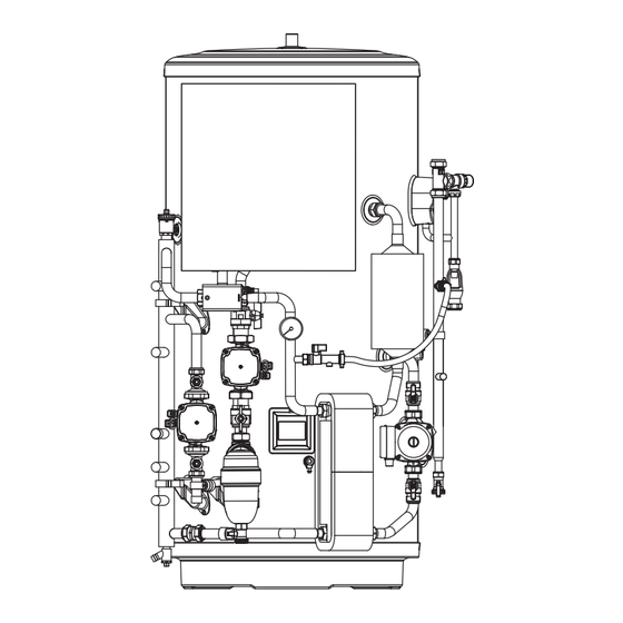
- Page 8 Fig. 1 - Parts Identification Hot Water Outlet FTC7 Controller Flow sensor (behind controller) Expansion Valve Temperature/Pressure Relief Valve Automatic Air Vent THW5A thermistor boss Tundish Low loss header 3 Way motorised Scale Trap diverter valve Primary circuit pressure gauge Expansion vessel tapping Heat Pump circulating...
- Page 9 Fig. 2a - Dimensions and EU Product Fiche - 28 mm Standard Models C & E OVERALL HEIGHT SECONDARY RETURN TAPPING HEAT PUMP FLOW CONNECTION (28 mm O/D COPPER) TUNDISH OUTLET CONNECTION (22 mm COMPRESSION) HEAT PUMP RETURN CONNECTION (28 mm O/D COPPER) HEATING ZONE 1 CIRCUIT FLOW CONNECTION (22 mm O/D COPPER) HEATING ZONE 1 CIRCUIT RETURN CONNECTION (22 mm O/D COPPER) COLD WATER INLET CONNECTION (22 mm COMPRESSION)
- Page 10 Fig. 2b - Dimensions and EU Product Fiche - 22 mm Standard Models C & E OVERALL HEIGHT SECONDARY RETURN TAPPING (NOT FITTED TO EHPT15X-UKHEWS/ EHPT17X-UKHEWS) HEAT PUMP FLOW CONNECTION (22 mm O/D COPPER) TUNDISH OUTLET CONNECTION (22 mm COMPRESSION) HEAT PUMP RETURN CONNECTION (22 mm O/D COPPER) HEATING ZONE 1 CIRCUIT FLOW CONNECTION (22 mm O/D COPPER) HEATING ZONE 1 CIRCUIT RETURN CONNECTION (22 mm O/D COPPER)
- Page 11 HOT WATER OUTLET CONNECTION (22 mm COMPRESSION/3/4 “ BSP M) THW5A SENSOR POCKET Wi-Fi ADAPTOR (INCLUDED, INSTALLER TO LOCATE AND MOUNT) CAPACITY 1516 1690 1127 1127 MODEL EHPT17X-UKHLEWS EHPT15X-UKHLEWS 1083 Energy efficiency class 1127 1127 58.3 66.3 Standing loss in W...
- Page 12 Table 2 - STANDARD Cylinder Technical Data...
- Page 13 Table 3 - SLIMLINE Cylinder Technical Data...
- Page 14 HEAT PUMP CIRCULATION PUMP (GRUNDFOS UPM4L 25-75 130AZA) Graph 1 - UPM4L 25-75 130AZA Performance Curves QH Chart Q [m3/h] Five pump speed control is available via FTC7 control. Power Chart Q [m3/h] Pump speed can be selected by main remote controller setting (see Graph 1, red curves). Adjust the pump speed setting so that the flow rate in the primary circuit is appropriate for the outdoor unit installed.
- Page 15 HEATING ZONE 1 CIRCULATION PUMP (GRUNDFOS UPM3 AUTO 25-70 130) When you switch on the pump it will run to the pre-set position or the last setting. The diagram below shows the current operation status. To change the pump setting, follow below: (a) Press the ‘...
- Page 16 • PP1: Lowest proportional Control Mode explanation pressure curve • PP2: Intermediate Proportional pressure proportional pressure The head pressure is reduced at falling heat demand curve and increased at rising heat demand. The duty point of the circulator will move up or down •...
- Page 17 Graph 3 - Cylinder Pressure Drop Pressure Drop for Small Cylinder Models (22 mm) Hot Water Circuit Space Heating Circuit Flow rate (l/min) Pressure Drop for Large Cylinder Models (28 mm) Hot Water Circuit Space Heating Circuit Flow rate (l/min)
- Page 18 INSTALLATION – GENERAL PIPE FITTINGS The connection points to the heating system are in 22 mm copper pipe. The use of appropriately sized COMPRESSION FITTINGS is recommended when connecting to the pipes. Solder fittings can be used, but extreme care must be taken to ensure any ancillary components in close proximity are not damaged by heat.
- Page 19 DRAIN TAPS Drain taps are fitted to both the primary system pipe work and to the cold water inlet to facilitate draining the unit or indirect heating circuit for maintenance purposes. It is recommended that the outlet point of the drain pipe work be at least 1 metre below the level of the heater (this can be achieved by attaching a hose pipe to the drain tap outlet spigot).
- Page 20 Fig. 7 - Schematic installation diagram...
- Page 21 INSTALLATION - DISCHARGE It is a requirement of Building Regulation G3 that any discharge from an unvented system is conveyed to where it is visible, but will not cause danger to persons in or about the building. The tundish and discharge pipes should be fitted in accordance with the requirements and guidance notes of Building Regulation G3.
- Page 22 Note: An alternative approach for sizing discharge pipes would be to follow Annex D, section D.2 of BS 6700:2006 +A1:2009 Specification for design, installation, testing and maintenance of services supplying water for domestic use within buildings and their curtilages. 3.59 Where a single common discharge pipe serves more than one system, it should be at least one pipe size larger than the largest individual discharge pipe(D2) to be connected.
- Page 23 Table 4 - Sizing of copper discharge pipe (D2) for common temperature relief valve outlet sizes MAXIMUM RESISTANCE MINIMUM SIZE ALLOWED, RESISTANCE MINIMUM SIZE VALVE OUTLET OF DISCHARGE EXPRESSED AS CREATED BY OF DISCHARGE SIZE PIPE D2 FROM A LENGTH OF EACH ELBOW PIPE D1 TUNDISH...
- Page 24 INSTALLATION - HEAT PUMP PRIMARY CIRCUIT HEAT PUMP SELECTION • The Pre-plumbed cylinders are suitable for use with an Ecodan PUZ-WZ or PUZ-(H)WM Air Source heat pump. • If in doubt consult Mitsubishi Electric for further advice. • Solid fuel boilers or any other boiler in which the energy input is not under effective thermostatic control unless additional and appropriate safety measures are installed should NOT be used.
- Page 25 If the interlock operation of primary and secondary pump is available ensure minimum water volume in primary and secondary circuit. If the interlock of operation of primary and secondary pump is not available ensure minimum water volume in only primary circuit. In case of shortage of minimum water volume install a buffer tank. SIZING EXPANSION VESSELS Expansion vessel volume must fit the local system water volume.
- Page 26 MAIN REMOTE CONTROLLER - FLOW SENSOR FLOW RATE RANGE Adjust the flow sensor minimum flow rate setting from the default value of 5L/min to the required value of 7L/min for the following models only: EHPT21X-UKHEWL, EHPT25X-UKHEWL & EHPT30X-UKHEWL The flow sensor flow rate settings can be accessed via the auxiliary settings within the service menu. <Main Controller Menu Tree>...
- Page 27 WIRING All electrical wiring should be carried out by a competent electrician and be in accordance with the latest I.E.E. Wiring Regulations. The Pre-plumbed cylinder thermal controls and circulating pumps are factory pre-wired. Further wiring will be required between the FTC7 controller, the programmer, room temperature sensor and the Heat Pump. Additional controls and wiring will be required if a second space heating zone is to be fitted to the installation.
- Page 28 Fig. 11 - Optional 2 zone control pack – dip switch settings Default settings: DIP switch Function Indoor unit model SW1 SW1-1 Boiler WITHOUT Boiler WITH Boiler SW1-2 Heat pump maximum outlet water temperature 55 ºC 60 ºC SW1-3 DHW tank WITHOUT DHW tank WITH DHW tank SW1-4 Immersion heater...
- Page 29 Fig. 12 - Optional 2 zone twin temperature control pack - plumbing schematic Zone1 Zone2 Fig. 13 - Optional 2 zone twin temperature control pack - component wiring Secondary Z1 Flow TBO.1 CN01 ( BK) CNP1 ( WH) CN3C CNP4 ( BU) TBO.2 ( RD)
- Page 30 Fig. 14 - Optional 2 zone twin temperature control pack - sensor wiring TBO.1 CN01 ( BK) CNP1 ( WH) TBI.5 7-8 (THW6) CN3C CNP4 ( BU) TBO.2 ( RD) LED1 Secondary Z1 Flow CNPWM ( WH) CNV1 TBO.3 ( WH) Mixing Valve CNRF ( WH)
- Page 31 Fig. 16 - Wiring of Motorised Mixing valve Fig. 17 - Schematic of Motorised Mixing Valve hydraulic connections to Zone2 heat emitter from mixing tank (Master) Motorized mixing valve to mixing tank from Zone2 heat emitter TBO.2 1 2 3 Close N Open Fig.
- Page 32 ELECTRICAL WORK Electrical connection date product warranty. All wiring should be according to national wiring regula- tions. For multiple outdoor units control with FTC (Sub), see section 9. Clamps FTC (Main) can be powered in two ways. 1. Power cable is run from the outdoor unit to FTC (Main). 2.
- Page 33 ELECTRICAL WORK Option 2: FTC (Main) powered by independent source If FTC (Main) and outdoor units have separate power supplies, the following re- quirements must be carried out: • FTC (Main) unit electrical box connector connections changed. (see Fig. Initial settings CN01 4.1.3) (Power supplied...
- Page 38 Fig. 20 - Routing of mains, immersion heater & remote controller cables Remote 230 V mains Controller Immersion Heater...
- Page 40 INSTALLATION - Wi-Fi ADAPTER The pre-plumbed cylinder units are supplied fitted with a Wi-Fi adapter which can be used to easily pair your Ecodan system to the internet to enable remote control, monitoring, maintenance and technical support. The Wi-Fi adapter is pre-wired to the FTC controller and is contained within a transport bag at the front of the unit.
- Page 42 Back Next Comfort Packaged type Outdoor Unit Model PUZ-WM50VHA(-BS) PUZ-WM60VAA(-BS) PUZ-WM85V/YAA(-BS) Indoor Unit Model PUZ-WM112VAA(-BS) PUZ-HWM140V/YHA(-BS) 150-O1 EHPT15X-UKHLEWS (150L) 150-O1 150-O1 EHPT17X-UKHLEWS (170L) 170-O1 170-O1 170-O1 EHPT15X-UKHLEWS (150L) EHPT15X-UKHEWS (150L) 150-O1 150-O1 150-O1 EHPT17X-UKHEWS (170L) 170-O1 170-O1 170-O1 210-O1 210-O1...
- Page 53 COMMISSIONING At the time of commissioning, please ensure the Commissioning Checklist is completed for the installation. CYLINDER UNIT - INITIAL FILL PROCEDURE • BEFORE FILLING CHECK AND TIGHTEN ALL MECHANICAL JOINTS AND CONNECTIONS IN CASE THESE HAVE LOOSENED DURING TRANSIT. •...
- Page 54 Notes...
- Page 55 Notes...
- Page 56 ENVIRONMENTAL INFORMATION Products are manufactured from many recyclable materials. At the end of their useful life they should be disposed of at a Local Authority Recycling Centre in order to realise the full environmental benefits. Insulation is by means of an approved CFC/HCFC free polyurethane foam with an ozone depletion factor of zero. WEEE Declaration Disposal of Waste Equipment by Users in Private Household in the European Union.
Need help?
Do you have a question about the EHPT17X-UKHLEWS and is the answer not in the manual?
Questions and answers