
Subscribe to Our Youtube Channel
Related Manuals for Megger MOM200A


Summary of Contents for Megger MOM200A
- Page 1 MOM200A/600A Micro-ohmmeters User’s Manual ZP-BB04E BB0141NE 2015 Art No. Doc.
- Page 3 © 2013, Megger Sweden AB. All rights reserved. The contents of this manual are the property of Megger Sweden AB. No part of this work may be reproduced or transmitted in any form or by any means, except as permitted in written license agreement with Megger Sweden AB. Megger Sweden AB has made every reasonable attempt to ensure the completeness and accuracy of this document.
-
Page 4: Table Of Contents
............. 8 General ..............8 Symbols on the instrument ........8 Safety instructions ..........8 3 Control panels ............10 Control panel – MOM200A ......10 Control panel – MOM600A ......11 4 Operating instructions ............12 External measuring instrument....... 13 Troubleshooting ............. 13 5 Application examples ............ - Page 5 BB0141NE ZP-BB04E MOM200A/600A...
-
Page 6: Introduction
To protect against external overvoltages, both the current output and the sensing input are decoupled to ground. MOM200A is used for currents up to 200 A. MOM600A can provide an output current of up to 600 A, and it can be set to six different measuring ranges. - Page 7 1 INTrODuCTION BB0141NE ZP-BB04E MOM200A/600A...
-
Page 8: Safety
Do not use any accessories that are not inten- ded for use together with the instrument. Disconnect the instrument from the mains before cleaning. use a damp cloth for cleaning. Do not use liquid cleaners or aerosol cleaners. MOM200A/600A ZP-BB04E BB0141NE... - Page 9 If you need to return the instrument, please use either the original crate or one of equivalent strength. BB0141NE ZP-BB04E MOM200A/600A...
-
Page 10: Control Panels
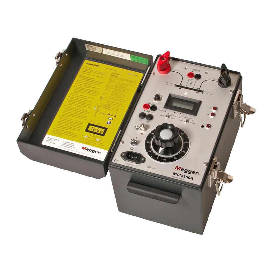
3 CONTrOL PANELS Control panels Control panel – MOM200A Mains inlet LED, resistance Positive current output (I LED, current Sensing terminal (SENSE) LED, thermal cut-out Negative current output (I Resistance range switch Resistance button (R) Test current switch Current-shunt terminal (SHUNT) -
Page 11: Control Panel - Mom600A
Miniature circuit breaker, 17 A Negative current output (I (F3, MOM600 115 V only) Resistance button (R) ON/OFF switch Test current push buttons Variable transformer Current-shunt terminal (SHUNT) Miniature circuit breaker for mains (F1) Grounding terminal Mains inlet BB0141NE ZP-BB04E MOM200A/600A... -
Page 12: Operating Instructions
Since power consumption is high, the instru- ment requires a 16 A fuse. On the MOM200A model, you must set the decimal point selector so that the decimal point is located correctly for the test current. If the display shows an "1" to the far left, the measuring range has been exceeded Fig. -
Page 13: External Measuring Instrument
(on model MOM600A) or milliohms (on model MOM200A). The current flowing through the test object is interrupted auto- matically, but the reading remains visible on the display. -
Page 14: Application Examples
Measuring resistance in a Connect the micro-ohmmeter to the mains. Turn on the ON/OFF switch. breaker MOM200A: Select the desired current (100 A for example) using the "Test current switch". Important MOM600A: Select the desired current (100 A Read the manual and comply with the for example) using the proper "Test current... -
Page 15: Measuring Resistance At Bus-Bar Joints
Connect the micro-ohmmeter to the mains. Turn on the ON/OFF switch. MOM200A: Select the desired current (100 A for example) using the "Test current switch". MOM600A: Select the desired current (100 A BB0141NE... -
Page 16: Expanded Measuring Range
To obtain the correct resistance reading you must multiply the displayed reading by a factor of X. To obtain X, divide the selected current setting by the generated current. Example: 400/100 = 4. MOM200A/600A ZP-BB04E BB0141NE... - Page 17 6 SPECIFICATIONS BB0141NE ZP-BB04E MOM200A/600A...
-
Page 18: Specifications
6 SPECIFICATIONS Specifications Specifications MOM200A Specifications MOM600A Specifications are valid at nominal input voltage and an ambient Specifications are valid at nominal input voltage and an ambi- temperature of +25°C, (77°F). Specifications are subject to ent temperature of +25°C, (77°F). Specifications are subject to change without notice. - Page 19 Input cur- current output load time rent voltage time 100 A DC 8.3 V – – 300 A DC 7.2 V 2.5 min. 15 min. 16 A 600 A DC 5.6 V 15 s 5 min. 32 A BB0141NE ZP-BB04E MOM200A/600A...
- Page 20 ▪ Insulation Power Factor (C&DF) Test Equipment worldwide. ▪ Insulation Resistance Test Equipment Megger is certified according to ISO 9001 and 14001. ▪ Line Testing Equipment Megger is a registered trademark. ▪ Low Resistance Ohmmeters Megger Group Limited ▪...
Need help?
Do you have a question about the MOM200A and is the answer not in the manual?
Questions and answers