
Related Manuals for General CA10


Summary of Contents for General CA10
- Page 1 AC CIRCUIT ANALYZER USER’S MANUAL CA10 Please read this manual carefully and thoroughly before using this product.
-
Page 2: Table Of Contents
Return for Repair Policy ....... . . 15 INTRODUCTION The CA10 is a special-purpose electrical tester designed to quickly identify and locate single faults in low-voltage (120VAC) distribution lines (branch circuits). -
Page 3: Key Features
Do not use this instrument on circuits carrying voltages higher than 120VAC. WHAT’S IN THE BOX The CA10 comes in an illustrated box containing a soft canvas carrying case. Inside the case are the instrument, a 6 ft. (1.83m) long test cable, six “AAA”... -
Page 4: Product Overview
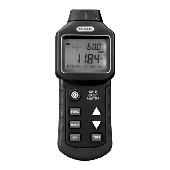
PRODUCT OVERVIEW Fig. 1 shows the controls, indicators and physical features of the CA10. Familiarize yourself with their names and functions before moving on to the Setup Instructions and Operating Instructions. Fig. 2 shows all possible indications on the CA10’s LCD. -
Page 5: Setup Instructions
MEASURING VOLTAGE PARAMETERS The CA10 can measure four parameters of an AC circuit voltage: 1) the True RMS value of its phase voltage (L-N), 2) the True RMS voltage to earth (ground) of its neutral line (N-E), 3) the peak value of the voltage (Peak), and 4) the frequency of the voltage. - Page 6 To begin, plug the free end of the test cable into any outlet of the circuit to be tested. Press the button to cycle through the three submenu options in either direction, as shown in the figure below. The text icon of the parameter being measured appears at the left of the display.
-
Page 7: Measuring Voltage Drop
MEASURING VOLTAGE DROP The CA10 can calculate and display a circuit’s voltage drop in response to application of a 12A, 15A or 20A dummy load. In all three cases, the voltage drop displayed on-screen as a percentage is based on the True RMS value of the drop on the circuit’s phase (live) line. - Page 8 The table below lists the possible causes of an abnormal result and suggests remedies and additional troubleshooting steps to take. Possible Cause Parameter Normal Actual Result Remedy Measurement of Abnormal Result Result Circuit is overloaded Redistribute load Conductors are too Replace wiring with thin for circuit heavier-gauge conductors...
-
Page 9: Measuring Conductor Impedance
MEASURING CONDUCTOR IMPEDANCE The CA10 can measure and display the impedance of all three circuit conductors as well as one impedance-related parameter (available short-circuit current, or ASCC). The three impedance values represent the impedances of the phase (live) line (Z-L), the neutral line (Z-N), and the earth (ground) line (Z-E). - Page 10 The table below the figure shows the normal measurement result for each of the four parameters. It also lists possible causes of, and remedies for, abnormal results. Parameter Normal Actual Result Remedy Possible Cause Measurement of Abnormal Result Result <0.15 /m for Circuit is overloaded Redistribute circuit load 14AWG conductor...
-
Page 11: Testing Residual Current Devices (Rcds)
2-wire systems. TESTING RESIDUAL CURRENT DEVICES (RCDs) The CA10 can measure how much current it takes to trip an RCD, and how quickly it responds to an event that should cause a trip. It does so by placing a resistance across the circuit’s live and ground lines, generating a current... -
Page 12: Testing Ground Fault Circuit Interrupters (Gfcis)
TESTING GROUND FAULT CIRCUIT INTERRUPTERS (GFCIs) The CA10 can measure how much current it takes to trip a GFCI, and how quickly it responds to a condition that should cause a trip. It does so by placing a resistance across the circuit’s live and ground lines, generating a current between them. -
Page 13: Other Functions
Auto Power Off (APO). A 30-minute APO function is automatically enabled when the CA10 is powered on. When APO is enabled (indicated by a clock icon ( ) at the upper left of the display), if no button is pushed for 30 minutes the CA10 will automatically power off to extend battery life. -
Page 14: Specifications
“AAA” batteries. Follow the instructions on p. 5 for opening and closing the battery compartment and installing the batteries. HOUSEKEEPING HINTS DO NOT expose the CA10 to: • Direct sunlight • High humidity or temperatures (above 104°F/40°C during operation or 140°F/60°C in storage) -
Page 15: Warranty Information
Do not open the housing of the unit. Doing so voids its limited warranty and could disable its safety circuitry. You may clean the housing of the CA10 with a soft, clean cloth and water or a mild detergent. Never use benzene, alcohol, acetone, ether, ketone, paint thinner, gasoline or an organic solvent. - Page 16 FAX (212) 431-6499 TOLL FREE (800) 697-8665 e-mail: sales@generaltools.com www.generaltools.com CA10 User’s Manual Specifications subject to change without notice ©2016 GENERAL TOOLS & INSTRUMENTS NOTICE - WE ARE NOT RESPONSIBLE FOR TYPOGRAPHICAL ERRORS. MAN#CA10 3/17/16 GeneralToolsNYC General Tools & Instruments...
Need help?
Do you have a question about the CA10 and is the answer not in the manual?
Questions and answers